Ecco EC7008-WK2 Instructions D'installation
Table des Matières
Les langues disponibles
Les langues disponibles
Liens rapides
IMPORTANT! Read all instructions before installing and using. Installer: This manual must be delivered to the end user.
WARNING!
Failure to install or use this product according to manufacturer's recommendations may result in property damage, serious injury, and/
or death to those you are seeking to protect!
Do not install and/or operate this safety product unless you have read and understood the safety information
contained in this manual.
1.
Proper installation combined with operator training in the use, care, and maintenance of emergency warning devices are essential to
ensure the safety of emergency personnel and the public.
2.
Emergency warning devices often require high electrical voltages and/or currents. Exercise caution when working with live electrical
connections.
3.
This product must be properly grounded. Inadequate grounding and/or shorting of electrical connections can cause high current arcing,
which can cause personal injury and/or severe vehicle damage, including fire.
4.
Proper placement and installation is vital to the performance of this warning device. Install this product so that output performance of
the system is maximized and the controls are placed within convenient reach of the operator so that they can operate the system without
losing eye contact with the roadway.
5.
Do not install this product or route any wires in the deployment area of an air bag. Equipment mounted or located in an air bag
deployment area may reduce the effectiveness of the air bag or become a projectile that could cause serious personal injury or death.
Refer to the vehicle owner's manual for the air bag deployment area. It is the responsibility of the user/operator to determine a suitable
mounting location ensuring the safety of all passengers inside the vehicle particularly avoiding areas of potential head impact.
6.
It is the responsibility of the vehicle operator to ensure daily that all features of this product work correctly. In use, the vehicle operator
should ensure the projection of the warning signal is not blocked by vehicle components (i.e., open trunks or compartment doors),
people, vehicles or other obstructions.
7.
The use of this or any other warning device does not ensure all drivers can or will observe or react to an emergency warning signal.
Never take the right-of-way for granted. It is the vehicle operator's responsibility to be sure they can proceed safely before entering an
intersection, drive against traffic, respond at a high rate of speed, or walk on or around traffic lanes.
8.
This equipment is intended for use by authorized personnel only. The user is responsible for understanding and obeying all laws
regarding emergency warning devices. Therefore, the user should check all applicable city, state, and federal laws and regulations. The
manufacturer assumes no liability for any loss resulting from the use of this warning device.
Installation, Wiring and Function
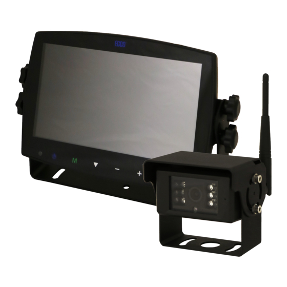
CAMERA SYSTEM MODEL EC7008-WK2
OPERATING INSTRUCTIONS:
Remote
Remote
Control
Control
Sensor
Sensor
Power
Power
Menu
Menu
Record/Select
Record/Select
Digital Color LCD Screen
Digital Color LED Screen
M
S
Camera Channel Select
Camera Channel Select
Volume Increase/Menu Navigation
Volume Increase/Menu Navigation
Volume Decrease/
Volume Decrease/Menu
Navigation
Menu Navigation
Installation Instructions
Wireless Camera/Monitor System
CAUTION!
When drilling into any vehicle surface, make sure that the
area is free from any electrical wires, fuel lines, vehicle
upholstery, etc. that could be damaged.
Ecante-5
Ecante-5
Loudspeaker
Loudspeaker
Dimming Sensor
Dimming Sensor
U-Support Bracket
U-Support Bracket
Mini SD Card
Mini SD Card Slot
Slot
Pedestal Mount Slot
Pedestal Mount Slot
Page 1 of 9
Table des Matières

Manuels Connexes pour Ecco EC7008-WK2

Sommaire des Matières pour Ecco EC7008-WK2
-
Page 19: Installation, Câblage Et Fonction
Installation, câblage et fonction ATTENTION! Lorsque vous percez un trou dans une surface de véhicule, assurez-vous que cette zone est exempte de fils électriques, SYSTÈME CAMÉRA MODÈLE EC7008-WK2 de canalisations d’essence, de garniture souple, etc. qui pourraient INSTRUCTIONS DE FONCTIONNEMENT : être endommagés. -
Page 20: Instructions De Câblage
Important ! Imperméabilisez toutes les connexions à l'intérieur ou à l'extérieur du véhicule à l'aide d’un agent d'étanchéité et l'enrubannage avec du ruban isolant. Enveloppez hermétiquement de bandes qui se chevauchent, par une demi-largeur pour éviter les lacunes. INSTRUCTIONS DE CÂBLAGE : Remarques : 1. -
Page 21: Identification De Pièces De L'écran
IDENTIFICATION DE PIÈCES DE L’ÉCRAN Appuyez pour activer ou Press to enable or Press to turn on/off Appuyez pour activer désactiver la sourdine disable mute the monitor ou désactiver l’écran MUTE POWER Press OK button to Appuyez sur OK pour Press to show menu Appuyez pour accéder au menu ou... -
Page 22: Contrôle De L'enregistrement
MODE D’AFFICHAGE LECTURE Le nombre de dossiers augmente automatiquement au fur et à mesure que les fichiers d’enregistrement augmentent, un dossier contient au maximum 997 fichiers vidéo. Un nouveau dossier est automatiquement créé lorsqu’un dossier est plein. Plus le numéro de fichier est élevé, plus le fichier est •... - Page 23 RÉGLAGE SYSTÈME La valeur gradateur peut être réglée lorsque Auto est sur désactivé. • Sélectionnez pour définir la valeur du gradateur de jour et de nuit. Appuyez sur la touche M sur le moniteur ou MENU de la télécommande pour sauvegarder et quitter le menu.
- Page 24 MISE SOUS TENSION DATE ET HEURE • Sélectionnez l’icône correspondante pour afficher le clavier et régler la date et l’heure. • Appuyez sur la touche « + » ou « – » sur le moniteur ou VOL+/– de la • Sélectionnez la vue que vous souhaitez afficher à la mise sous tension. télécommande pour passer à...
- Page 25 Figure 2 Figure 3 Instructions de montage sur socle : 1. Sélectionnez une surface plane pour l'installation. 2. Pour monter le socle à l'aide d’un adhésif, préparez la surface en la frottant avec de l'alcool avant l'installation. 3. Pour monter le socle à l'aide de vis, percez les trous de montage en utilisant le socle comme gabarit et fixez-le avec le matériel fourni par l'utilisateur. 4.
-
Page 26: Pour Référence Seulement
CAMÉRA MODÈLE EC2027-WC2 INSTALLATION ET MONTAGE : Important ! Monter la caméra à un endroit qui offre le meilleur point de vue de la zone immédiatement derrière le véhicule. En général, les points de montage vers le haut du véhicule offrent le meilleur champ de vision. Les emplacements de montage inférieurs réduisent le champ de vision et augmentent la probabilité... -
Page 27: Lux (Jour), 0 Lux (Avec Ir)
Spécifications : Caméra EC2027-WC2 Écran Écran PEX EC7008-WK2 7 po Périphérique d'image 1/3 po CMOS Taille PEX 7 po Système de télévision PAL/NTSC Résolution 1024 x 3 (RGB) x 600 Taille du tableau 728x488 Pixels Contraste 800:1 Zone de détection 4,6228mm x 3,6112mm Luminosité...