Publicité
Les langues disponibles
Les langues disponibles
Liens rapides
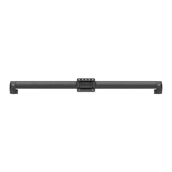
26400 - Kolpin Utility Gear Rail System
ITEM
Spare P/N
1
N/A
2
76400
3
76401
4
76402
5
76403
6
76404
7
8
9
87036
10
11
76405
12
(Hardware Pack)
13
14
1
5
*Sides are determined when looking from the rear of the machine
Rev. 03
DESCRIPTION
ALUMINUM EXTRUSION
PLASTIC C-CLAMP
L.H. EXTRUSION END CAP
R.H. EXTRUSION END CAP
L.H. PLASTIC CLAMP BACK
R.H. PLASTIC CLAMP BACK
MOUNTING BASE PLATE
MOUNTING BRACKET PLATE
STAR TURN KNOB
¼" X 3/4" TRUSS HEAD BOLT
¼" X 2.25" TRUSS HEAD BOLT
¼" X 5.50" TRUSS HEAD BOLT
¼" NYLOCK NUT
¼" X 5/8" ALLEN HEAD BOLT (20035)
3
6
QTY
1
1
1
1
1
1
1
1
1
8
8
8
12
8
2
9
4
Publicité

Manuels Connexes pour Kolpin 26400

Sommaire des Matières pour Kolpin 26400
- Page 1 Rev. 03 26400 - Kolpin Utility Gear Rail System ITEM Spare P/N DESCRIPTION ALUMINUM EXTRUSION 76400 PLASTIC C-CLAMP 76401 L.H. EXTRUSION END CAP 76402 R.H. EXTRUSION END CAP 76403 L.H. PLASTIC CLAMP BACK 76404 R.H. PLASTIC CLAMP BACK MOUNTING BASE PLATE...
- Page 2 Rev. 03 WARNINGS/NOTES/SAFTEY INFORMATION NOTE: Retain these installation instructions with the machine operator's manual. NOTE: Never transport a loaded weapon in the Kolpin Gun Boot®. Operating Safely • Before shifting into reverse, always check for obstacles or people behind the machine.
- Page 3 Rev. 03 STEP BY STEP INSTRUCTIONS: Using the 4 – ¼” x 2.25” or the 5.50” Truss Head Bolts and ¼” Nylock Nuts mount the Left Hand Extrusion End Cap on the dump bed side of the driver side roll bar. (Left side if looking from the back of the machine).
- Page 4 Note: Over tightening can cause damage to the system or brackets. Very little torque is needed to hold the system securely. 4. The 26500 Bracket ( also sold separately) is compatible with the following Kolpin Products: A. Gun Boot 5.0 (20090-95) E.
-
Page 5: Mounting Instructions
2. Mount the bracket to the C-Clamp by attaching the remaining (4) Truss Head bolts to the four corners of the C-Clamp. 3. The C-Clamp then slides onto the 26400 Utility Gear Rail System. Tighten the C-Clamp using the Star Turn Knob provided. -
Page 6: Système De Barre À Équipement Kolpin
Rev. 03 26400 – Système de barre à équipement Kolpin Réf. de pièce Désignation Qté s.o. Barre en aluminium extrudé 76400 Pince en C en plastique 76401 Capuchon de barre gauche 76402 Capuchon de barre droit 76403 Pince en plastique gauche... -
Page 7: Façons D'utiliser Le Système De Barre À Équipement Kolpin
Remarque : Un serrage excessif des pièces peut endommager le système ou les supports. Il suffit d’un couple de serrage très peu élevé pour bien fixer le système. FAÇONS D’UTILISER LE SYSTÈME DE BARRE À ÉQUIPEMENT KOLPIN... - Page 8 Rev. 03 MODE D’INSTALLATION PAR ÉTAPES 1. À l’aide de 4 boulons de 1/4 x 2,25 po ou de 4 boulons à tête bombée de 5,50 po (réf. 9 ou 10), et des écrous de 1/4 po à frein élastique (11), montez le capuchon de barre gauche (3) sur le côté benne basculante de l’arceau côté...
- Page 9 Remarque : Un serrage excessif des pièces peut endommager le système ou les supports. Il suffit d’un couple de serrage très peu élevé pour bien fixer le système. 4. Le support 26500 (vendu séparément) est compatible avec les produits Kolpin suivants : A. Fourreau Gun Boot 5.0 (20090-95) E.