Eden ACCESS-IT UNIT Notice Technique
Table des Matières
Les langues disponibles
Les langues disponibles
Liens rapides
Table des Matières

Manuels Connexes pour Eden ACCESS-IT UNIT

Sommaire des Matières pour Eden ACCESS-IT UNIT
- Page 1 Contrôle d’accès Access control ACCESS-IT UNIT Notice technique / Technical information...
-
Page 2: Table Des Matières
Information and recommendations ......24 1) ACCESS-IT UNIT ........5 Technical characteristic ..........25 Schéma type pour raccorder ......... 6 1) ACCESS-IT UNIT ......25 1) Antenne active ........6 Typical arrangement for connection......26 2) Technologies d’identification 1) Active aerial ........26... -
Page 3: Remerciements
Vous venez de faire l’acquisition d’une centrale « ACCESS-IT UNIT » créée par la société française EDEN. Toute l’équipe EDEN vous remercie de votre intérêt ainsi que de votre confiance pour notre solution de sécurité. Nous espérons qu’elle vous donnera entière satisfaction dans la sécurisation des locaux de votre entreprise. -
Page 4: Informations Et Recommandations
Informations et recommandations o Conformément à la directive européenne UTE C00-200 décrivant les directives 89/336CEE et 92/31 CEE, ACCESS-IT UNIT est conforme aux normes : • NF EN 50081-1 pour les émissions électromagnétiques et • NF EN 50082-1 pour la susceptibilité électromagnétique. -
Page 5: Caractéristiques Techniques
Technical information ACCESS-IT UNIT p.5/42 Caractéristiques techniques 1) ACCESS-IT UNIT Consommation maximale ....300 mA Tension d’alimentation ..... 9 – 14 VDC Poids avec le boîtier ......1,05 kg Dimensions du boîtier ....... 340 x 280 x 75 cm Température de fonctionnement ..+ 20 C à... -
Page 6: Schéma Type Pour Raccorder
Technical information ACCESS-IT UNIT p.6/42 Schéma type pour raccorder 1) Antenne active Récepteur Radio (JCM, TECHNO EM,…) (?) Fiche technique : 3 fils 100 m Ø 0,6 mm Caractéristique : Liaison sensible Écran : Facultatif Il suffit de raccorder les trois fils du lecteur sur le bornier de la centrale comme indiqué ci-contre. -
Page 7: Technologies D'identification Utilisant Le Protocole Wiegand / Clock&Data
Technical information ACCESS-IT UNIT p.7/42 2) Technologies d’identification utilisant le protocole WIEGAND / Clock&Data WIEGAND : o Lecteurs de proximité (HID, STID, DESTEIR, INDALA, …) o Claviers (XPR, …) o Lecteurs biométriques (SAGEM, …) o Récepteurs radio (JCM, TECHNO EM, …) o DALLAS (via interface TMCD20) CLOCK&DATA :... -
Page 8: Lecteur Solo-Ai (Rs485)
Technical information ACCESS-IT UNIT p.8/42 3) Lecteur SOLO-AI (RS485) Vous pouvez raccorder jusqu’à 2 SOLO-AI par ACCESS-IT Note : UNIT (?) Fiche technique : Veillez à utiliser une même paire pour A et B Veillez à séparer l’alimentation du bus RS485 Caractéristique :... -
Page 9: Lecteur Biovein (Rs485)
Pour atteindre 1 200 m, vous devez installer à chaque extrémité du réseau une résistance de 220 entre les points A et B (cf. ci-dessus). Attention : Pour raccorder les lecteurs BIOVEIN, la version de votre centrale ACCESS-IT UNIT doit être 1.1 ou supérieure. La version de ACCESS-IT LOG doit être 2.0.0 ou supérieure. -
Page 10: Modules D'extensions Infx2-Ai Et Outfx2-Ai (Rs485)
5) Modules d’extensions INFX2-AI et OUTFX2-AI (RS485) ALIMENTATION 12Vcc RS485 Vous pouvez raccorder : o 5 INFX2 maximum sur une ACCESS-IT UNIT o 5 OUTFX2 maximum sur une ACCESS-IT UNIT (?) Fiche technique : Veillez à utiliser une même paire pour A et B Veillez à... -
Page 11: Schéma Type Pour Raccorder
Technical information ACCESS-IT UNIT p.11/42 Schéma type pour raccorder 1) Gâche à rupture de courant et ventouse électromagnétique fonctionnant par manque de courant Diode anti-retour Alimentation +12V 0V Afin d’éviter tous dysfonctionnements aléatoires qui viendraient perturber la bonne utilisation Attention : du système due à... -
Page 12: Gâche Standard : Fonctionnement À Émission De Tension
Technical information ACCESS-IT UNIT p.12/42 2) Gâche standard : fonctionnement à émission de tension Diode anti-retour Alimentation +12V 0V Afin d’éviter tous dysfonctionnements aléatoires qui viendraient perturber la bonne utilisation Attention : du système due à des courants de retour, il est impératif d’utiliser et de raccorder les diodes anti-retour livrées avec la centrale suivant le schéma de câblage ci-dessus. -
Page 13: Utilisation Des Menus
Technical information ACCESS-IT UNIT p.13/42 Utilisation des menus La centrale possède un menu de configuration. Pour y accéder, appuyez sur un des 4 boutons présents sous l’afficheur. Pour naviguer dans les menus, utilisez les touches « + » et « - ». Pour rentrer dans un menu, utilisez la touche «... -
Page 14: Utilisation Des Touches De La Centrale
Technical information ACCESS-IT UNIT p.14/42 2) Utilisation des touches de la centrale La centrale comporte quatre touches réparties comme suit : Touche Défilement Touche Validation Touche Annulation Touche Défilement (sortir d’un menu / inférieur (Valider un menu / supérieur ( - ) -
Page 15: Consultation Des Événements
Technical information ACCESS-IT UNIT p.15/42 o Supprimer des utilisateurs : La suppression s’effectue de la même manière que pour l’ajout d’un utilisateur. o Parcourir la liste Ce menu vous donne la possibilité de vérifier la liste des utilisateurs enregistrés dans la centrale. -
Page 16: Mode De Communication
Technical information ACCESS-IT UNIT p.16/42 REGLAGE DU Réglage du contraste CONTRASTE Ce menu vous permet de régler le contraste de l’afficheur à l’aide des touches « + » et « - ». Pour sortir du menu, appuyez sur la touche « V ». - Page 17 Technical information ACCESS-IT UNIT p.17/42 Ce menu se compose de : Sélectionner l’entrée à utiliser ainsi que le type de EFFRACTION BOITIER contact pour surveiller les effractions sur le boîtier. Interdit deux passages successifs d’un badge sur le même lecteur. Pour cela, Un badge valide doit entrer ANTI-PaASS-BACK par un lecteur d’entrée et sortir par un lecteur de...
-
Page 18: Paramétrage Du Lecteur
Technical information ACCESS-IT UNIT p.18/42 TYPE DE LECTEUR 2 Idem que le menu précédent. STANDARD Pour le type de lecteur BioFx 485, vous devrez saisir son identifiant (ID sur l’étiquette de numéro de série du produit ainsi que son niveau de sécurité (taux de fausse acceptation) et son niveau de sensibilité... -
Page 19: Paramétrage Des Codes
Technical information ACCESS-IT UNIT p.19/42 Vous pouvez paramétrer jusqu’à 32 plages horaires sur 8 jours (Lundi au Dimanche plus jours fériés) de 10 créneaux par jour. 1) Sélectionnez la plage à configurer à l’aide des touches de défilement « + » et « - » puis appuyez sur « V »... -
Page 20: Utilisation En Mode Centralisé
Technical information ACCESS-IT UNIT p.20/42 Utilisation en mode centralisé Vous devez impérativement configurer une adresse à votre centrale. Pour cela, utilisez le menu de la centrale puis allez dans le menu « Mode de Communication » pour saisir l’adresse de la centrale (de 1 à 32). -
Page 21: Autres Modes De Communication
Technical information ACCESS-IT UNIT p.21/42 2) Autres modes de communication Mode de Désignation Désignation communication COMETEFX-AI Raccordement d’un bus RS485 de plusieurs centrales sur le réseau Ethernet en filaire C485FX-AI + MOD- Réseau Ethernet TCPIP-AI (TCP/IP) : LAN, Raccordement d’une seule centrale sur le réseau... -
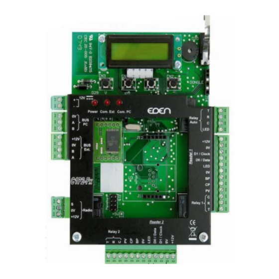
Page 22: Fonctions Des Bornes
Technical information ACCESS-IT UNIT p.22/42 Fonctions des bornes +12V Alimentation BUS 485 PC +12V BUS 485 Carte d’extension Antenne active +12V Relais Lecteur 2...