Table des Matières
Publicité
Les langues disponibles
Les langues disponibles
Liens rapides
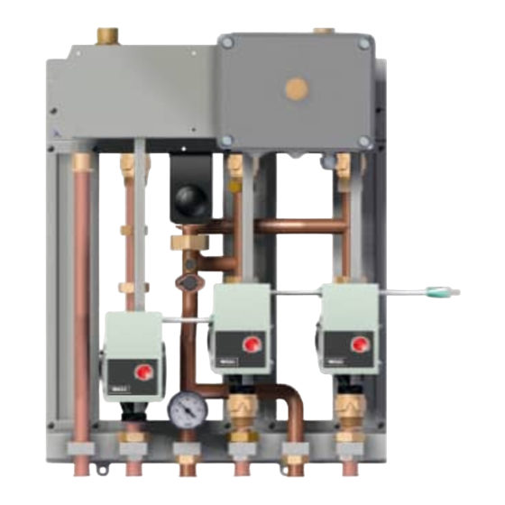
MS UNIVERSALE+
SISTEMA PER LA GESTIONE DI UN IMPIANTO MISTO AD INCASSO
CONTROLLER FOR BUILT-IN TWIN-CIRCUIT INSTALLATIONS
APPAREIL POUR LA GESTION D'UN CIRCUIT MIXTE A ENCASTRER
STEUERUNGSSYSTEM FÜR INTEGRIERTE ZWEIKREISANLAGEN
ISTRUZIONI DI INSTALLAZIONE
it
en
INSTALLATION INSTRUCTIONS
INSTRUCTIONS D'INSTALLATION
fr
EINBAUANLEITUNG
de
Publicité
Chapitres
Table des Matières

Manuels Connexes pour Baxi MS UNIVERSALE+


Sommaire des Matières pour Baxi MS UNIVERSALE+
- Page 1 MS UNIVERSALE+ SISTEMA PER LA GESTIONE DI UN IMPIANTO MISTO AD INCASSO CONTROLLER FOR BUILT-IN TWIN-CIRCUIT INSTALLATIONS APPAREIL POUR LA GESTION D’UN CIRCUIT MIXTE A ENCASTRER STEUERUNGSSYSTEM FÜR INTEGRIERTE ZWEIKREISANLAGEN ISTRUZIONI DI INSTALLAZIONE INSTALLATION INSTRUCTIONS INSTRUCTIONS D’INSTALLATION EINBAUANLEITUNG...
-
Page 2: Table Des Matières
Le parti dell’imballo (sacchetti in plastica, polistirolo ecc.) non devono essere lasciate alla portata dei bambini in quanto potenziali fonti di pericolo. BAXI S.p.A. dichiara che questi modelli di caldaie sono dotati di marcatura CE confor- memente ai requisiti essenziali delle seguenti Direttive: - Direttiva Compatibilità... -
Page 3: Installazione
2. INSTALLAZIONE I’ apparecchio va installato all’interno della cassa/dima che è fornita in un imballo a parte. Assicurarsi che il modello della cassa dima sia corretto. 2.1 INSTALLAZIONE CASSA DIMA La cassa/dima deve essere inserita nel muro in una nicchia ricavata a tale scopo (dimensioni riportate in figura 1) e bloccata con le apposite zanche laterali. - Page 4 VISTA DAL BASSO Ø 36 mm Mbt1 Rbt1 Mbt2 Rbt2 57,5 65 67,5 67,5 67,5 67,5 57,5 82,5 136,5 Legenda forometrie cassetta incasso kit impianto misto: M - Mandata da Caldaia R - Ritorno a caldaia Mat - Mandata alta temperatura Mbt1 - Mandata bassa temperatura 1°...
-
Page 5: Dimensioni E Attacchi Idraulici
3. DIMENSIONI E ATTACCHI IDRAULICI 60,5 149,5 Legenda : G3/4” M: mandata da caldaia G3/4” M: ritorno in caldaia G3/4” F: mandata impianto alta temperatura ≤ 80°C G3/4” F: ritorno impianto alta temperatura MBT1 G3/4” F: mandata 1 zona bassa temperatura ≤... -
Page 6: Prevalenze Pompe
4. PREVALENZE POMPE Le sezioni del circuito devono essere calcolate secondo i normali metodi, tenendo conto della caratteristica portata- prevalenza disponibile alla placca di seguito riportate. 4.1. POMPE CIRCUITI BASSA TEMPERATURA REGOLAZIONE POMPA p-c (costante) PORTATA ACQUA (l/h) REGOLAZIONE POMPA p-v (variabile) PORTATA ACQUA (l/h) ISTRUZIONI DI INSTALLAZIONE 7225991.02- it... - Page 7 4.2. POMPA CIRCUITO ALTA TEMPERATURA REGOLAZIONE POMPA p-c (costante) PORTATA ACQUA (l/h) REGOLAZIONE POMPA p-v (variabile) PORTATA ACQUA (l/h) ISTRUZIONI DI INSTALLAZIONE 7225991.02- it...
-
Page 8: Regolazione Delle Pompe Automodulanti
4.3 REGOLAZIONE DELLE POMPE AUTOMODULANTI Le pompe automodulanti sono dotate di una Degasamento impianto manopola con la quale è possibile attivare e di- sattivare tutte le funzioni e di un indicatore a LED posizionato intorno alla manopola stessa. Nella tabella che segue è riportata la diagnostica ed il significato della segnalazione luminosa del LED. -
Page 9: Schema Elettrico
5.1. SCHEMA ELETTRICO 6 5 4 3 2 1 Figura 4 ISTRUZIONI DI INSTALLAZIONE 7225991.02- it... - Page 10 5.2 LEGENDA CONNETTORI ENTRATE USCITE X7: 1-2 Ingresso termostato ambiente zona alta temperatura (TA3) X7: 3-4 Ingresso termostato ambiente 2 zona bassa temperatura (TA2) X7: 5-6 Ingresso termostato ambiente 1 zona bassa temperatura (TA1) X11: 1-2 Collegamento ingresso TA di caldaia X3: 1 (F) - 2 (N) Alimentazione pompa prima zona bassa temperatura X3: 3 (F) - 4 (N) Alimentazione pompa seconda zona bassa temperatura(*) X3: 5 (F) - 6 (N) Alimentazione pompa zona alta temperatura (*)
- Page 11 5.5 COLLEGAMENTO TERMOSTATO AMBIENTE ZONA ALTA TEMPERATURA (TA3) Utilizzare un termostato ambiente (fornito come accessorio) Il contatto del termostato ambiente della zona ALTA temperatura (TA3), deve essere collegato al connettore X7 morsetti 1-2 del MS UNIVERSALE+ (figura 4). Utilizzare un cavo a due poli armonizzato “HAR H05 VV-F” 2x0,75 mm 5.6 COLLEGAMENTO CAVO ATTIVAZIONE CALDAIA I morsetti 1-2 del connettore X11 del MS UNIVERSALE+ (figura 4) devono essere collegati all’ingresso destinato al termo- stato ambiente della caldaia (Morsettiera M1).
-
Page 12: Configurazione Della Scheda Elettronica
6. CONFIGURAZIONE DELLA SCHEDA ELETTRONICA Terminati tutti i collegamenti idraulici ed elettrici, la scheda elettronica deve essere configurata mediante il tasto “ Pcnf ” presente sulla scatola elettrica (figura 3). La configurazione si rende necessaria al fine di far riconoscere alla scheda elettronica le periferiche impiegate (es. sonda esterna, valvola a tre vie, sonda NTC, ecc.). -
Page 13: Legenda Comandi E Led Scheda
7. LEGENDA COMANDI E LED SCHEDA POTENZIOMETRI P1 Potenziometro regolazione della curva climatica (0-9: vedere grafico al paragrafo 5.7) P2 Potenziometro regolazione della temperatura impianto a bassa temperatura (25-45 °C) P3 Potenziometro di regolazione tempo postcircolazione pompa (3’– 212’) Nota: con potenziometro posizionato sul valore massimo, la postcircolazione è continua. LEGENDA LED LED LA Acceso fisso... -
Page 14: Gestione E Regolazione Zone
8. GESTIONE E REGOLAZIONE ZONE (Vedere anche quanto riportato nel manuale di caldaia) Caldaie con regolatore climatico Caldaie senza regolatore climatico Zona 1 (TA1) Bassa temperatura Regolatore climatico Termostato ambiente Zona 2 (TA2) Bassa temperatura Termostato ambiente Termostato ambiente Zona 3 (TA3) Alta temperatura Termostato ambiente Termostato ambiente... -
Page 15: Fine Vita Prodotto
10 Kg BAXI S.p.A., nella costante azione di miglioramento dei prodotti, si riserva la possibilità di modificare i dati espressi in questa documentazione in qualsiasi momento e senza preavviso. La presente documentazione è un supporto informativo e non considerabile come contratto nei confronti di terzi. - Page 16 Do not leave any packaging (plastic bags, polystyrene, etc.) within the reach of children as they are a potential source of danger. BAXI S.p.A. declares that these models of boiler bear the CE mark in compliance with the basic requirements of the following Directives:...
-
Page 17: Installing The Template Box
2. INSTALLATION The appliance must be installed inside the template box which is supplied in a separate package. Ensure that the model of the template box is correct. 2.1 INSTALLING THE TEMPLATE BOX The template box must be fitted into the wall in a niche created for the purpose (dimensions shown in Figure 1), and blo- cked with special rag bolts at the sides. - Page 18 BOTTOM VIEW Ø 36 mm Mbt1 Rbt1 Mbt2 Rbt2 57,5 65 67,5 67,5 67,5 67,5 57,5 82,5 136,5 Key to holes for built-in box mixed system kit : Delivery from boiler Return to boiler High temperature delivery Mbt1 Low temperature delivery 1st zone Mbt2 Low temperature delivery 2nd zone High temperature return...
-
Page 19: Dimensions And Hydraulic Fittings
3. DIMENSIONS AND HYDRAULIC FITTINGS 60,5 149,5 Key : G3/4” M: delivery from boiler G3/4” M: return to boiler G3/4” F: high temperature sy- stem delivery < 80°C G3/4” F: high temperature system return MBT1 G3/4” F: 1st low temperature zone delivery <... -
Page 20: Pump Heads
4. PUMP HEADS Calculate the circuit sections as usual, bearing in mind the flow-head available for the system, as listed below. 4.1. LOW TEMPERATURE CIRCUITS PUMPS ADJUSTING THE PUMP ∆p-c (constant) WATER FLOW l / h ADJUSTING THE PUMP ∆p-v (variable) WATER FLOW l / h INSTALLATION INSTRUCTIONS 7225991.02 - en... - Page 21 4.2. HIGH TEMPERATURE CIRCUIT PUMP ADJUSTING THE PUMP ∆p-c (constant) WATER FLOW l / h ADJUSTING THE PUMP ∆p-v (variable) WATER FLOW l / h INSTALLATION INSTRUCTIONS 7225991.02 - en...
-
Page 22: Electrical Connection
4.3. ADJUSTING THE SELF-MODULATING PUMPS The self-modulating pumps have a knob for Degassing the system enabling and disabling all the functions, and a LED indicator around the same knob. The dia- gnostics and meaning of the light signals of the LED are indicated in the table below. -
Page 23: Wiring Diagram
5.1. WIRING DIAGRAM 6 5 4 3 2 1 Figure 4 INSTALLATION INSTRUCTIONS 7225991.02 - en... - Page 24 5.2 KEY TO OUTPUT AND INPUT CONNECTORS X7: 1-2 High temperature zone ambient thermostat input (TA3) X7: 3-4 2nd low temperature zone ambient thermostat input (TA2) X7 : 5-6 1st low temperature zone ambient thermostat input (TA1) X11: 1-2 Boiler TA input connection X3: 1 (F) - 2 (N) 1st low temperature zone pump power supply X3: 3 (F) -4 (N) 2nd low temperature zone pump power supply (*) X3: 5 (F) -6 (N) High temperature zone pump power supply (*)
- Page 25 5.5 HIGH TEMPERATURE ZONE AMBIENT THERMOSTAT CONNECTION (TA3) Use an ambient thermostat (supplied as an accessory). The contact of the ambient thermostat of the HIGH temperature zone (TA3) must be connected to the connector X7, terminals 1 -2 of the MS UNIVERSALE+ (Figure 4). Use a harmonised two-core cable “HAR H05 VV-F”...
-
Page 26: Configuring The Electronic Board
6. CONFIGURING THE ELECTRONIC BOARD Once all the hydraulic and electric connections have been completed, the electronic board must be configured by means of the button “Pcnf ”on the electric box (Figure 3). Configuration is necessary to enable the electronic board to recognise the peripherals used (e.g. external probe, three- way valve, NTC probe, etc.). -
Page 27: Key To Board Controls And Leds
7. KEY TO BOARD CONTROLS AND LEDS POTENTIOMETERS Potentiometer for regulating the climate curve (0-9: see graph in paragraph 5.7) Potentiometer for regulating the system temperature at low temperature (25-45 °C) Potentiometer for regulating the pump post-circulation time (3’– 212’) PUMP POST-CIRCULATION CLIMATE CURVE LOW TEMPERATURE SYSTEM... -
Page 28: Zone Management And Regulation
8. ZONE MANAGEMENT AND REGULATION (See also the instructions in the boiler manual) Boilers with climate controller Boilers without climate controller zone 1 (TA1) Low temperature Climate controller Ambient thermostat zone 2 (TA2) Low temperature Ambient thermostat Ambient thermostat zone 3 (TA3) High temperature Ambient thermostat Ambient thermostat... -
Page 29: End Of The Product's Working Life
10 Kg As Baxi S.p.A. constantly strives to improve its products, it reserves the right to modify the information contained in this document at any time and without prior notice. This document is issued purely for the sake information and should not be considered as a contract with third... - Page 30 SOMMAIRE 1. Description 2. Installation 3. Dimensions et raccords hydrauliques 4. Hauteurs manométriques des pompes 5. Raccordement électrique 6. Configuration de la carte électronique 7. Légende des commandes et LEDS de la carte 8. Gestion et réglage des zones 9. Fin de vie du produit 10.
-
Page 31: Installation
2. INSTALLATION L’appareil doit être installé à l’intérieur du corps d’encastrement fourni sous emballage séparé. S’assurer que le modèle du corps d’encastrement est correct. 2.1 INSTALLATION DU CORPS D’ENCASTREMENT Le corps d’encastrement doit être inséré dans le mur dans une niche découpée à cet effet (dimensions indiquées à la figure 1) et être ensuite bloqué... - Page 32 VU D’EN DESSOUS Ø 36 mm Mbt1 Rbt1 Mbt2 Rbt2 57,5 65 67,5 67,5 67,5 67,5 57,5 82,5 136,5 Légende perçage pour le corps d’encastrement kit installation mixte : Refoulement de la chaudière Retour à la chaudière Refoulement haute température Mbt1 Refoulement basse température zone 1 Mbt2...
-
Page 33: Dimensions Et Raccords Hydrauliques
3. DIMENSIONS ET RACCORDS HYDRAULIQUES 60,5 149,5 Légende : G3/4” M : refoulement de la chaudière G3/4” M : retour à la chaudière G3/4” F : refoulement installation haute température ≤ 80 ° C G3/4” F : retour installation haute température Mbt1 G3/4”... -
Page 34: Hauteurs Manométriques Des Pompes
4. HAUTEURS MANOMETRIQUES DES POMPES Les sections du circuit doivent être calculées selon les méthodes classiques, en tenant compte des caractéristiques de débit et de hauteur manométriques disponibles de l’installation reportées ci-dessous. 4.1. POMPES CIRCUITS BASSE TEMPERATURE REGLAGE DES POMPES ∆p-c (constant) DÉBIT EAU l / h REGLAGE DES POMPES ∆p-v (variable) DÉBIT EAU l / h... - Page 35 4.2. CIRCUIT DE POMPE HAUTE TEMPERATURE REGLAGE DES POMPES ∆p-c (constant) DÉBIT EAU l / h REGLAGE DES POMPES ∆p-v (variable) DÉBIT EAU l / h INSTRUCTIONS D’INSTALLATION 7225991.02 - fr...
-
Page 36: Réglage Des Pompes Auto-Modulantes
4.3. RÉGLAGE DES POMPES AUTO-MODULANTES Les pompes auto-modulantes sont dotées Purge installation d’un bouton avec lequel il est possible d’activer et désactiver toutes les fonctions et d’un indi- cateur à LED positionné autour du bouton. Le tableau qui suit indique le diagnostic et la signi- fication des signalisations lumineuses du LED. -
Page 37: Diagramme De Connexion
5.1. DIAGRAMME DE CONNEXION 6 5 4 3 2 1 Figure 4 INSTRUCTIONS D’INSTALLATION 7225991.02 - fr... -
Page 38: Legende Connecteurs Entrees Sorties
5.2 LEGENDE CONNECTEURS ENTREES SORTIES X7 : 1-2 Entrée thermostat zone haute température (TA3) X7 : 3-4 Entrée thermostat 2ème zone basse température (TA2) X7 : 5-6 Entrée thermostat 1ère zone basse température (TA1) X11 : 1-2 Raccordement entrée TA de la chaudière X3 : 1 (F) - 2 (N) Alimentation pompe première zone basse température X3 : 3 (F) - 4 (N) Alimentation pompe seconde zone basse température (*) X3 : 5 (F) - 6 (N) Alimentation pompe zone haute température (*) -
Page 39: Raccordement Du Cable D'activation De La Chaudiere
5.5 RACCORDEMENT THERMOSTAT D’AMBIANCE AVANT LA ZONE HAUTE TEMPERATURE (TA3) Utiliser un thermostat d’ambiance (fourni comme accessoire) Le contact du thermostat d’ambiance de la zone haute température (TA3) doit être raccordé au connecteur X7 borne 1 - 2 de la carte du MS UNIVERSALE+ (figure 4). Utiliser un câble à... -
Page 40: Configuration De La Carte Électronique
6. CONFIGURATION DE LA CARTE ELECTRONIQUE Lorsque tous les raccordement hydrauliques et électriques auront été effectués, il sera nécessaire de configurer la carte électronique à l’aide de la touche « Tcnf » présente sur le coffret électrique (figure 3), afin que la carte électronique soit en mesure de reconnaître les différents périphériques installés ( comme une sonde extérieure, une vanne trois voies, des sondes NTC, etc.). -
Page 41: Legende Des Commandes Et Des Leds De La Carte
7. LEGENDE DES COMMANDES ET DES LEDS DE LA CARTE POTENTIOMÈTRES Potentiomètre de réglage de la courbe de chauffe (0-9 : voir le tableau au paragraphe 5.7) Potentiomètre de régulage de la température de l’installation basse température (25-45 °C) Potentiomètre de réglage du temps de postcirculation de la pompe (3’– 212’) POTENTIOMÈTRE DURÉE POTENTIOMÈTRE TEMP. -
Page 42: Gestion Et Réglage Des Zones
8. GESTION ET REGLAGE DES ZONES (Consulter également le manuel de la chaudière) Chaudières Chaudières avec régulateur climatique sans régulateur climatique zone 1 (TA1) Basse température Régulateur climatique Thermostat d’ambiance zone 2 (TA2) Basse température Thermostat d’ambiance Thermostat d’ambiance zone 3 (TA3) Haute température Thermostat d’ambiance Thermostat d’ambiance... -
Page 43: Fin De Vie Du Produit
10 Kg BAXI S.p.A. déclares que les descriptions et caractéristiques figurant sur ce document sont données à titre d’information et non d’engagement. En effet, soucieux de la qualité de nos produits, nous nous réservons le droit d’effectuer, sans préavis, toute modification ou amélioration INSTRUCTIONS D’INSTALLATION... -
Page 44: Beschreibung
Verpackungsmaterialien (Plastiktüten, Styropor etc.) stellen eine potentielle Gefahren- quelle dar, halten Sie diese daher außerhalb der Reichweite von Kindern. BAXI S.p.A. erklärt, dass diese Heizungsmodelle eine CE-Kennzeichnung besitzen und den grundlegenden Anforderungen der folgenden Richtlinien entsprechen : - EMV-Richtlinie 2004/108/EG... -
Page 45: Installation
2. INSTALLATION Das Gerät muss in der Template-Box installiert werden, die in einem separaten Paket geliefert wird. Vergewissern Sie sich, dass Sie das richtige Template-Box-Modell zur Hand haben. 2.1 EINBAU DER TEMPLATE-BOX Die Template-Box muss in eine eigens für diesen Zweck gebaute Wandnische (Maße in Abbildung 1) eingesetzt und seitlich mit Spezial-Klauenschrauben gesichert werden. - Page 46 ANSICHT VON UNTEN Ø 36 mm Mbt1 Rbt1 Mbt2 Rbt2 57,5 65 67,5 67,5 67,5 67,5 57,5 82,5 136,5 Legende der Öffnungen für die in die Box integrierte Mischsystem-Baugruppe : Zuleitung von der Therme Rücklauf zur Therme Hochtemperaturvorlauf Mbt1 Niedertemperaturvorlauf 1. Zone Mbt2 Niedertemperaturvorlauf 2.
-
Page 47: Abmessungen Und Hydraulikanschlüsse
3. ABMESSUNGEN UND HYDRAULIKANSCHLÜSSE 60,5 149,5 Legende : G3/4” M: Zuleitung von der Therme G3/4” M: Rücklauf zur Therme G3/4” F: Hochtemperatursystem Vorlauf < 80°C G3/4” F: Hochtemperatursystem Rücklauf MBT1 G3/4” F: 1. Niedertemperaturzone Vorlauf < 45°C RBT1 G3/4” F: 1. Niedertemperaturzone Rücklauf MBT2 G3/4”... -
Page 48: Pumpen Förderhöhe
4. PUMPEN FÖRDERHÖHE Berechnen Sie die Schaltungsteile auf übliche Weise und berücksichtigen Sie dabei die für das System verfügbare För- derhöhe, wie unten angegeben.. 4.1. NIEDERTEMPERATUR HEIZKREISPUMPEN PUMPE REGELN ∆p-c (konstant) WASSERDURCHFLUSS l / h PUMPE REGELN ∆p-v (variabel) WASSERDURCHFLUSS l / h EINBAUANLEITUNG 7225991.02 - de... - Page 49 4.2. HOCHTEMPERATURKREISPUMPE PUMPE REGELN ∆p-c (konstant) WASSERDURCHFLUSS l / h PUMPE REGELN ∆p-v (variabel) WASSERDURCHFLUSS l / h EINBAUANLEITUNG 7225991.02 - de...
-
Page 50: Elektrischer Anschluss
4.3. SELBSTMODULIERENDE PUMPEN REGELN Die selbstmodulierenden Pumpen besitzen einen Entgasung der Anlage Drehschalter, mit dem alle Funktionen ein- und ausgeschaltet werden können, sowie eine LED-An- zeige am Drehschalter selbst. In der folgenden Ta- belle ist die Diagnose und die Bedeutung der LED- Anzeige angegeben. - Page 51 5.1. SCHALTBILD 6 5 4 3 2 1 Abbildung 4 EINBAUANLEITUNG 7225991.02 - de...
- Page 52 5.2 LEGENDE DER EIN- UND AUSGANGSANSCHLÜSSE X7: 1-2 Hochtemperaturzone Raumthermostat Eingang (TA3) X7: 3-4 2. Niedertemperaturzone Raumthermostat Eingang (TA2) X7: 5-6 1. Niedertemperaturzone Raumthermostat Eingang (TA2) X11: 1-2 Therme TA Eingangsanschluss X3: 1 (F) - 2 (N) 1. Niedertemperaturzone Pumpe Stromversorgung X3: 3 (F) - 4 (N) 2.
- Page 53 5.5 HOCHTEMPERATURZONE RAUMTHERMOSTATANSCHLUSS (TA3) Verwenden Sie einen Raumthermostat (als Zubehör erhältlich). Der Kontakt des Raumthermostats der HOCHtemperaturzone (TA3) ist mit Anschluss X7, Klemmen 1-2 auf der Platine des MS UNIVERSALE+ (Abbildung 4) zu verbinden. Verwenden Sie dazu ein harmonisiertes zweiadriges „HAR H05 VV-F” 2 x 0,75 mm Kabel.
-
Page 54: Konfiguration Der Elektronikplatine
6. KONFIGURATION DER ELEKTRONIKPLATINE Sobald die hydraulischen und elektrischen Anschlüsse fertig gestellt wurden, muss die Elektronikplatine über die Taste „Pcnf” im Schaltschrank konfiguriert werden (Abbildung 3). Die Konfiguration ist notwendig, damit die Elektronikplatine die verwendeten Peripheriegeräte erkennt (z.B. externer Tem- peraturfühler, Dreiwegeventil, NTC-Fühler etc.). -
Page 55: Legende Der Platinensteuerung Und Leds
7. LEGENDE DER PLATINENSTEUERUNG UND LEDS POTENTIOMETER Potentiometer zur Regulierung der Klimakurve (0-9: Siehe Diagramm in Absatz 5.7) Potentiometer zur Regulierung der Systemtemperatur bei niedrigen Temperaturen (25-45°C) Potentiometer zur Regulierung der Nachlaufzeit der Pumpe (3’ - 212’) NIEDERTEMPERATUR PUMPEN-NACHLAUFZEIT KLIMAKURVEN- SYSTEMTEMPERATUR POTENTIOMETER POTENTIOMETER... -
Page 56: Zonensteuerung Und Regelung
8. ZONENSTEUERUNG UND REGELUNG (Lesen Sie auch die Anweisungen im Handbuch der Therme) Heiztherme mit Klimaregler Heiztherme ohne Klimaregler Zone 1 (TA1) Niedertemperatur Klimaregler Raumthermostat Zone 2 (TA2) Niedertemperatur Raumthermostat Raumthermostat Zone 3 (TA3) Hochtemperatur Raumthermostat Raumthermostat 8.1 ERSTE NIEDERTEMPERATURZONE (TA1) Diese Zone kann mit dem Klimaregler der Therme (sofern vorhanden) oder mit einem als Zubehör lieferbaren Raumther- mostat geregelt werden. -
Page 57: Ende Der Nutzungsdauer Des Produkts
Gewicht Gehäusekasten 10 Kg Baxi S.p.A. ist bemüht, seine Produkte kontinuierlich zu verbessern und behält sich das Recht vor, die in diesem Dokument enthaltenen Informationen jederzeit ohne Vorankündigung zu ändern. Dieses Dokument wurde ausschließlich zu Informationszwecken veröffentlicht und stellt keinen Vertrag mit Dritten dar. - Page 58 EINBAUANLEITUNG 7225991.02 - de...
- Page 59 EINBAUANLEITUNG 7225991.02 - de...
- Page 60 BAXI S.p.A. 36061 BASSANO DEL GRAPPA (VI) ITALIA Via Trozzetti, 20 Servizio clienti: Tel. 0424 - 517800 - Telefax 0424/38089 Ed. 1 - 11/15 cod. 7225991.02 www.baxi.it...