Greenheck SP110 Manuel D'installation, D'utilisation Et D'entretien
Table des Matières
Les langues disponibles
Les langues disponibles
Liens rapides
®
®
Installation, Operation and Maintenance Manual
Please read and save these instructions for future reference. Read carefully before attempting to assemble,
install, operate or maintain the product described. Protect yourself and others by observing all safety
information. Failure to comply with instructions could result in personal injury and/or property damage!
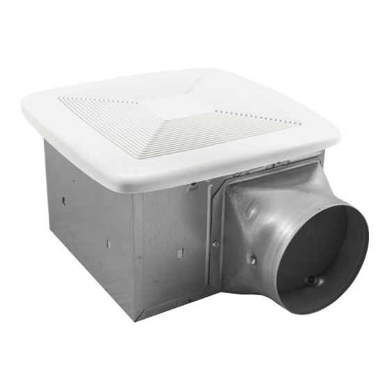
Model SP110 / SP80
Service Parts
Greenheck
Key
No.
Part No.
1
435100
Mounting Frame
2
435101
Knockout Plate & Screws
3
435102
Housing
4
435109
Wiring Panel/Harness Assembly
435104
Control Assembly & Motor (SP80)
5
435105
Control Assembly & Motor (SP110)
6
435106
Duct Connector - 6"
7
435107
6" to 4" Reducer (model SP80 only)
8
435108
Blower Wheel
9
435116
Scroll Assembly
10
435110
Grille Assembly (includes 11)
11
435111
Grille Spring (2 req'd)
Table of Contents
Warnings and Cautions ............................................ 2
Typical Installation .................................................... 2
New Construction Installation .................................. 3
Retrofit Installation ................................................... 7
®
Description
Easy installation in both new construction and retrofit.
6
7
Operation ................................................................ 11
Cleaning and Maintenance ..................................... 12
Troubleshooting ...................................................... 12
Our Commitment .................................................... 12
SP Ceiling Exhaust/Inline Fans
Document 99045143B
Model SP110/SP80
Multi-Speed
Ceiling Exhaust Fan
1
2
3
4
5
8
9
10
11
1
Table des Matières

Manuels Connexes pour Greenheck SP110


Sommaire des Matières pour Greenheck SP110
-
Page 13: Table Des Matières
Pour votre protection et celle des autres, respectez toutes les informations de sécurité. Toute infraction à ces instructions peut provoquer des blessures corporelles et des dommages matériels! Installation facile aussi bien dans les constructions Modèle SP110 / SP80 neuves que les rénovations. Pièces de rechange Greenheck N°... -
Page 14: Installation Typique
AVERTISSEMENT ATTENTION POUR RÉDUIRE LE RISQUE D’INCENDIE, DE CHOC À utiliser pour la ventilation générale uniquement. Ne ÉLECTRIQUE OU DE BLESSURE CORPORELLE, RESPECTER pas utiliser pour l’aspiration de matières et vapeurs CE QUI SUIT : dangereuses ou explosives. 1. Utiliser cet appareil exclusivement comme prévu par 1. -
Page 15: Installation Dans Une Construction Neuve
Installation dans une construction neuve Matériels nécessaire Outillage nécessaire • Gaine métallique ronde de 6 po conseillée pour un Visseuse électrique à embout Phillips fonctionnement optimal. L’utilisation d’autres gaines Tournevis Phillips est acceptable mais peut altérer les performances. Tournevis plat • Chapeau de toiture ou chapeau mural (registre Pince intégré... - Page 16 Installation dans une construction neuve 3 - Enclencher et fixer le caisson Placer le caisson entre les solives et pincer le profilé des deux côtés du bâti de montage pour bloquer le caisson en place. Ne pas Vis du sachet de pièces pincer le caisson.
-
Page 17: Raccorder Les Câbles Et Poser La Plaquette Défonçable
Installation dans une construction neuve 5 - Raccorder les câbles et poser la plaquette défonçable • Tirer un câble d’alimentation 120 Vc.a. jusqu’à l’emplacement de l’installation. • Utiliser des connecteurs homologués UL qui conviennent pour attacher le câble à la plaquette défonçable fournie dans le sachet de pièces. - Page 18 Installation dans une construction neuve 6 - Insérer le masque et finir le plafond • Poser le matériau de plafond. • Découper sur le pourtour du caisson. Le masque protège l’appareil durant la construction. L’enlever avant de poser la grille. 7 - Poser la grille REMARQUE : Voir Fonctionnement à...
-
Page 19: Installation De Rénovation
Installation de rénovation Matériels nécessaire Outillage nécessaire • Ruban d’étanchéité pour les raccordements de gaine Visseuse électrique à embout Phillips • La gaine rigide existante nécessitera l’ajout d’un Tournevis Phillips Règle courte longueur de gaine flexible Tournevis plat Crayon • Câblages et fournitures électriques conformes au Pince Scie pour cloison sèche code de l’électricité... - Page 20 Installation de rénovation 5 - Déposer la soufflante Conserver la soufflante Des deux côtés 6 - Déposer le panneau de câblage Conserver le panneau de câblage Conserver la vis 7 - Insérer le bâti de montage Déposer les vis du bâti de montage et les Plier les quatre pattes conserver...
-
Page 21: Enclencher Le Caisson
Installation de rénovation 8 - Fixer le bâti de montage Vis conservées à l’étape 7 9 - Enclencher le caisson Tirer le câblage existant dans le caisson lorsqu’il est inséré dans le bâti de montage 10 - Attacher la gaine et le connecteur de gaine Vis du sachet de pièces... -
Page 22: Poser La Plaquette Défonçable, Raccorder Les Câbles Et Poser Le Panneau De Câblage
Installation de rénovation 11 - Poser la plaquette défonçable, raccorder les câbles et poser le panneau de câblage • Utiliser des connecteurs homologués UL qui conviennent pour attacher le câble à la plaquette défonçable fournie dans le sachet de pièces. •... -
Page 23: Fonctionnement
Régler le débit d’air ajustable par l’utilisateur* Avec un petit tournevis plat, tourner avec précaution le réglage de débit d’air (CFM) pour faire pointer la flèche Commandes ajustables par l’utilisateur SP110 sur la valeur souhaitée (en pieds-cubes par minute). Ventilateurs d’extraction de plafond SP... -
Page 24: Nettoyage Et Entretien
(CFM). Notre engagement Dans le cadre de son engagement à l'amélioration continue de ses produits, Greenheck se réserve le droit de modifier leurs caractéristiques sans préavis. Les garanties sur les produits Greenheck particuliers se trouvent à greenheck.com, sous les onglets des produits et dans la bibliothèque (Library), sous Warranties.