Table des Matières

Publicité

Les langues disponibles
  • FR

Les langues disponibles

Liens rapides

SCT 415 S52
de Originalbetriebsanleitung
en Original instructions
fr
Notice originale
it
Istruzioni originali
ja
取扱説明書の原本
Kalibrier- und Justiervorrichtungen
Calibration and adjustment devices
Dispositifs d'ajustage et de calibrage
Kalibratie- en afstelinrichtingen
校正と調整デバイス

Publicité

Table des Matières
loading

Sommaire des Matières pour Bosch SCT 415 S52

  • Page 1 SCT 415 S52 de Originalbetriebsanleitung Kalibrier- und Justiervorrichtungen en Original instructions Calibration and adjustment devices Notice originale Dispositifs d‘ajustage et de calibrage Kalibratie- en afstelinrichtingen Istruzioni originali 取扱説明書の原本 校正と調整デバイス...
  • Page 3 | SCT 415 S52 | 3 de – Inhaltsverzeichnis en – Contents fr – Sommaire it – Indice jp – 目次 Robert Bosch GmbH 1 690 386 051 2020-10-22...
  • Page 4: Table Des Matières

    5.11 Einstellstange 9.5.13 Laserentfernungsmesser 5.12 Laser-Entfernungsmesser 5.13 Lasereinheit Technische Daten 5.14 P-Assist S5 / Halterung Einstellstange 10.1 Maße und Gewichte SCT 415 S52 5.15 Einstellstange in Halterung Einstellstange 10.2 Maße und Gewichte P-assist befestigen 10.2.1 Messmittel 5.16 Anleitung Rückseite Messtafel 10.2.2 Temperatur- und Arbeitsumgebung...
  • Page 5: Verwendete Symbolik

    Gefahr. Verwendung ¶ Das Signalwort zeigt die Eintrittswahrscheinlichkeit SCT 415 S52 ist nur zur statischen Kalibrierung von Sen- sowie die Schwere der Gefahr bei Missachtung: soren und Kameras an Kraftfahrzeugen verwenden. Maßgeblich sind die Fahrzeughersteller spezifischen Signalwort Eintrittswahrscheinlichkeit Schwere der Gefahr Reparatur- und Serviceanleitungen.
  • Page 6: Benutzerkreis

    6 | SCT 415 S52 | Wichtige Hinweise ¶ Gewährleistung Im Anschluss an Wartungs- und Instandsetzungsarbeiten immer unverzüglich die Sicherheitseinrichtungen montie- Die Verwendung von nicht frei gegebener Hard- und Soft- ren und überprüfen. ware führt zu einer Veränderung unserer Produkte und somit ¶...
  • Page 7: Mitgeltende Unterlagen

    Gefahr durch anzugsstarke Auf Verlangen der Berufsgenossenschaft ist ein Prüfbuch Magnete! mit bestimmten Eintragungen zu führen. Durch die starken Magnete des SCT 415 S52 können Personen mit Herzschrittmacher gefähr- det werden. Mitgeltende Unterlagen ¶ Mit den Magneten des SCT 415 S52 Abstand ¶...
  • Page 8: Lieferumfang

    Lieferumfang Benennung Bestellnummer Allgemein Grundplatte 1 690 381 267 SCT 415 S52 ist mit dem mobilen Grundplatte auf verschie- Einstellstange 1 690 381 118 den Messplätzen einsetzbar. Es besteht aus Grundplat- Säule 1 690 381 125 te, Säule, Einstellstange und P-Assist S5.
  • Page 9: Montage

    Montage | SCT 415 S52 | 9 Montage Anschlagblech ¶ Anschlagblech oben und unten entfernen. Grundplatte Säule auf Grundplatte montieren Zur einfachen Montage Säule liegend an Grundplatte befestigen. Position Arretiergriff zur Grundplatte beachten. Anschlagblech Distanzrohr ¶ Distanzrohr entfernen 1 Distanzrohr...
  • Page 10: Abdeckblech

    10 | SCT 415 S52 | Produktbeschreibung Abdeckblech Halter Messlineal ¶ ¶ Abdeckblech und Gummistreifen zur Seite schieben. Halter Messlineal oben und unten befestigen. Messlineal ¶ Messlineal durch Grundplatte führen und mit 1 Abdeckblech Schraube und Mutter sichern. 2 Gummistreifen Abstandshalter Richtung beachten.
  • Page 11: Zeiger Anbringen

    Produktbeschreibung | SCT 415 S52 | 11 Zeiger anbringen 5.11 Einstellstange ¶ 1. Blechschrauben lösen. Einstellstange anbringen 2. Zeiger anbringen und mit den Blechschrauben befesti- gen. 1 Halterung 2 Befestigung 3 Hebel Befestigung 4 Einstellstange 1. Befestigung durch Halterung anbringen.
  • Page 12: Laser-Entfernungsmesser

    12 | SCT 415 S52 | Produktbeschreibung 5.12 Laser-Entfernungsmesser 5.13 Lasereinheit ¶ 1. Batterien in Entfernungsmesser einlegen. Lasereinheit anbringen 2. Entfernungsmesser in Halterung befestigen. Bei Montage großer Tafeln, Halter "Laser-Entfer- nungsmesser" maximal ausziehen, wenn nötig, Posi- tion Laser verändern. 5.14 P-Assist S5 / Halterung Einstellstange 1.
  • Page 13: Einstellstange In Halterung Einstellstange Befestigen

    Produktbeschreibung | SCT 415 S52 | 13 5.15 Einstellstange in Halterung Einstell- 5.16 Anleitung Rückseite Messtafel stange befestigen 1. Einstellstange vorsichtig abstellen und in der Halte- Anleitung beachten bei Messtafeln: rung positionieren. 1 690 382 590 2. Taste im Kopf des Sicherungsstifts drücken und 1 690 382 608 halten.
  • Page 14: Große Tafel Montieren

    14 | SCT 415 S52 | Produktbeschreibung 5.17 Große Tafel montieren 5.18 Kleine Tafel montieren Abb. 5: Kleine Tafel an Schlitten befestigen 1 Sicherungsseil 2 Schlitten 3 Kleine Tafel 1. Kleine Tafel an Schlitten befestigen. Abb. 3: Große Tafel befestigen 2.
  • Page 15: Messplatz Voraussetzung

    Bewegen oder tragen nur über Strebenprofil. Umgebungsbedingungen Nicht an Verstelleinrichtung oder Halterung Laser tragen. 6.1.1 Ebenheit Messplatz Ebenheit am Messplatz von SCT 415 S52 darf 1 mm nicht über- Bei unebenen Boden besteht Kippgefahr. schreiten. Ebenheit der Aufstellfläche des Fahrzeugs ist 10 Positioniereinheit 6.1.2 Prüfplatzbedingungen...
  • Page 16: Bedienung

    SCT 415 S52 sind in den entsprechenden "Repara- gen. SCT 415 S52 vor Fahrzeug positionieren. turanleitungen" des Fahrzeugherstellers beschrie- 3. SCT 415 S52 mittig zwischen dem linken und rechten ben. Bodenmarkierungen F und E ausrichten, dabei Sicht- fenster im Grundplatte als Referenz verwenden.
  • Page 17: 8.3 Position Sct 415 S52 Korrigieren

    Bedienung | SCT 415 S52 | 17 90° Abb. 8: Nach Bodenmarkierung ausrichten Position SCT 415 S52 korrigieren 1 Laserstrahl 2 Bodenmarkierung 3 Ausrichtung Fahrzeug 1. Excenterspanner entriegeln. 2. Position korrigieren. 3. Excenterspanner verriegeln. Excenterspanner Robert Bosch GmbH 1 690 386 051...
  • Page 18: Sct 415 S52 Durch Fahrzeuglängs-Mittelebene Ausrichten

    SCT 415 S52 durch Fahrzeuglängs-  Laserlinie verläuft über das Fahrzeug. mittelebene ausrichten 4. SCT 415 S52 so ausrichten, dass das Hersteller-Emblem (Optional bei Benutzung von Lasermudul P-Assist S5) an der Fahrzeugfront und die Antenne durch die Laserlinie markiert werden.
  • Page 19: Präzisionshalter Ausrichten

    Stellfüße an der Grundplatte mit den Sterngriff- schrauben drehen. Für die statische Frontscheibenkamera-Kalibrierung muss SCT 415 S52 nach der Libelle für den Rollwinkel und der Libelle für den Nickwinkel ausgerichtet sein. Abb. 12: Entfernung mit Laser messen 1 Laserentfernungsmesser...
  • Page 20: Maßband Halterung Befestigen

    SCT 415 S52 mit Einstellhilfe ausrichten Die Einstellhilfe ist als Sonderzubehör erhältlich. 1. Einstellhilfe auf Sterngriffschraube aufsetzen. 2. SCT 415 S52 anhand der Libellen auf dem Präzisi- onshalter mit der Einstellhilfe ausrichten. Abb. 13: Maßband Halterung befestigen 1 Feststellschraube 2 Rändelschraube 1.
  • Page 21: Höhe Ablesen

    Bedienung | SCT 415 S52 | 21 8.11 Höhe ablesen Abb. 16: Höhe ablesen 1 Messlineal 2 Zeiger 3 Arretiergriff 4 Feststellschraube 1. Feststellschraube Messlineal lösen. 2. Messlineal bis zum Boden ablassen. Abb. 17: Messlineal am Boden 1 Messlineal 3. Mit dem Zeiger Höhe ablesen.
  • Page 22: Wartung

    22 | SCT 415 S52 | Wartung Wartung Ersatz- und Verschleißteile Überprüfung 9.5.1 Tafeln Einmal im Jahr SCT 415 S52 überprüfen lassen, um die Benennung Abb. Bestellnummer Einstellgenauigkeit sicherzustellen. 1 690 382 608 1) 2) Subaru 2S Magnete der Tafeln überprüfen, wenn notwendig reinigen.
  • Page 23 Wartung | SCT 415 S52 | 23 9.5.2 SCT 415 S52 Benennung Position Bestellnummer P-Assist S5 1 690 381 124 Schlitten links 1 690 381 123 Schlitten rechts 1 690 381 127 Einstellstange 1 690 381 118 Maßband rechts 1 693 740 649 Maßband links...
  • Page 24: 9.5.5 Schieber / Halterung Messlineal

    24 | SCT 415 S52 | Wartung 9.5.4 Grundplatte 9.5.5 Schieber / Halterung Messlineal / Messlineal Benennung Position Bestellnummer Teilesatz 1 690 381 149 Teilesatz 1 690 381 208 Grundplatte 1 690 381 267 Benennung Position Bestellnummer Schieber 1 690 382 280...
  • Page 25 Wartung | SCT 415 S52 | 25 9.5.6 Positioniereinheit 9.5.8 Maßbandhalter Benennung Position Bestellnummer Maßbandhalter – 1 690 381 206 9.5.9 Abstandshalter Benennung Position Bestellnummer Positioniereinheit 1 690 381 281 9.5.7 Einstellhilfe Benennung Position Bestellnummer Abstandshalter 1 690 382 669...
  • Page 26: Zeiger

    26 | SCT 415 S52 | Wartung 9.5.10 P-Assist S5 /Halterung Einstellstange 9.5.13 Laserentfernungsmesser Benennung Position Bestellnummer Laserentfernungsmesser 1 693 770 567 Halter für Laserentfer- 1 690 381 253 nungsmesser Schlitten für Laserentfer- 1 690 381 279 nungsmesser Benennung Position...
  • Page 27: 10. Technische Daten

    Technische Daten | SCT 415 S52 | 27 10. Technische Daten 10.1 Maße und Gewichte SCT 415 S52 Funktion Specifikation Abmessungen H x B x T 1800 x 2000 x 600 mm Gewicht 53 kg 10.2 Maße und Gewichte P-assist...
  • Page 28 – Contents Operation Alignment Symbols used Alignment example In the documentation Correcting the position of the SCT 415 S52 1.1.1 Warning notices - Aligning the SCT 415 S52 with the lengthwise Structure and meaning plane through center of vehicle 1.1.2...
  • Page 29: Symbols Used

    ¶ The SCT 415 S52 must only be used by trained and briefed personnel. The manufacturer (Bosch GmbH) Key word Probability of...
  • Page 30: Intended Users

    In any event, any liability on the part of Bosch GmbH is limited to the amount ac- tually paid by the customer for this product. This exemption from liability does not apply to damage intentionally caused or arising from gross negligence on the part of Bosch GmbH.
  • Page 31: Related Documents

    Danger from powerful mag- nets! Related documents The powerful magnets of the SCT 415 S52 are a All documents for the SCT 415 S52: potential risk for wearers of pacemakers. ¶ Keep the magnets of the SCT 415 S52 well...
  • Page 32: Scope Of Delivery

    Designation Part number General information Base plate 1 690 381 267 SCT 415 S52 can be used with the mobile base plate Cross beam 1 690 381 118 on various measurement bays. It consists of base plate, Column 1 690 381 125 column, cross beam, and P-Assist S5.
  • Page 33: Assembly

    Assembly | SCT 415 S52 | 33 Assembly Stop plate ¶ Remove stop plate at top and bottom. Base plate Mounting the column on the base plate To facilitate installation, attach the column to the base plate in a horizontal position.
  • Page 34: Cover Plate

    34 | SCT 415 S52 | Assembly Cover plate Ruler holder ¶ ¶ Push the cover plate and rubber strip to the side. Fasten ruler holder at top and bottom. Ruler ¶ Guide the ruler through the base plate and use the 1 Cover plate screw and nut to secure it.
  • Page 35: Attaching The Pointer

    Assembly | SCT 415 S52 | 35 5.11 Cross beam Attaching the pointer ¶ 1. Loosen the self-tapping screws. Attaching the cross beam. 2. Attach the indicator and secure it with the self-tapping screws. 1 Mounting 2 Fastener 3 Lever fastener 4 Cross beam 1.
  • Page 36: Laser Laser Tape Measure

    36 | SCT 415 S52 | Assembly 5.12 Laser tape measure 5.13 Laser unit ¶ 1. Place batteries in the tape measure. Attaching the laser unit 2. Fasten the tape measure in the mounting. When mounting large measurement boards, pull out the "Laser tape measure"...
  • Page 37: Securing The Cross Beam In The Cross Beam Mounting

    Assembly | SCT 415 S52 | 37 5.15 Securing the cross beam in the cross 5.16 Instructions on back of measurement beam mounting board 1. Carefully loosen cross beam and position it in the mounting. Follow the instructions for the measurement boards 2.
  • Page 38: Mounting The Large Measurement Board

    38 | SCT 415 S52 | Assembly 5.17 Mounting the large measurement 5.18 Mounting the small measurement board board Abb. 5: Fastening the small measurement board 1 Safety cord 2 Slide 3 Small measurement board 1. Attach the small measurement board to the slide.
  • Page 39: Measurement Bay Requirements

    7. Transport the SCT 415 S52. When moving, make sure that the cross beam does not strike anything. The SCT 415 S52 may be moved only by means of the column, not the cross beam. 1 Eccentric clamp 2 Movable plate...
  • Page 40: Operation

    SCT 415 S52 accordingly. The specific values for the exact alignment of the 2. Mark the floor for alignment. Place the SCT 415 S52 SCT 415 S52 are described in the car manufacturer's in front of the vehicle.
  • Page 41: 29 8.3 Correcting The Position Of The Sct 415 S52

    Operation | SCT 415 S52 | 41 90° Abb. 8: Alignment based on the floor markings Correcting the position of the 1 Laser beam SCT 415 S52 2 Floor marking 3 Vehicle alignment 1. Release the eccentric clamp. 2. Correct the position.
  • Page 42: Aligning The Sct 415 S52 With The Lengthwise

     The laser line now runs across the vehicle. vehicle 4. Align the SCT 415 S52 in such a way that the Optional when using the Greenline laser module manufacturer's badge on the front of the vehicle and (P-Assist S5) the antenna are highlighted by the laser line.
  • Page 43: 29 8.6 Aligning The Precision Holder

    For static windshield camera calibration, the SCT 415 S52 must be aligned using the roll angle and pitch angle spirit levels. Abb. 12: Measuring the distance with the laser...
  • Page 44: 29 8.8 Fastening The Tape Measure Holder

    "Repair instructions". 2. Check if there is a difference in height between the resting surface of the vehicle and the resting surface of the SCT 415 S52 (for example, because a lift is used). Abb. 14: Tape measure / mount 3.
  • Page 45: Reading Out The Height

    Operation | SCT 415 S52 | 45 8.11 Reading out the height Abb. 16: Reading out the height 1 Ruler 2 Pointer 3 Locking handle 4 Securing screw 1. Loosen the locking screw for ruler. 2. Lower the ruler to the floor.
  • Page 46: Maintenance

    46 | SCT 415 S52 | Maintenance Maintenance Spare and wearing parts Check 9.5.1 Measurement boards Have the SCT 415 S52 checked once a year to main- Designation Fig. Part number tain adjustment accuracy. 1 690 382 608 1) 2)
  • Page 47 Maintenance | SCT 415 S52 | 47 9.5.2 SCT 415 S52 Designation Item Part number Greenline laser mo- 1 690 381 124 dule (P-Assist S5) Left slide 1 690 381 123 Right slide 1 690 381 127 Cross beam 1 690 381 118...
  • Page 48: 33 9.5.4 Base Plate

    48 | SCT 415 S52 | Maintenance 9.5.4 Base plate 9.5.5 Slide / ruler mounting / ruler Designation Item Part number Parts set 1 690 381 149 Parts set 1 690 381 208 Base plate 1 690 381 267 Designation...
  • Page 49: 33 9.5.6 Distance Reference Stand

    Maintenance | SCT 415 S52 | 49 9.5.6 Distance reference stand Designation Item Part number Tape measure – 1 690 381 206 mount 9.5.9 Spacer Designation Item Part number Distance reference stand 1 690 381 281 9.5.7 Setting aid Designation...
  • Page 50: P-Assist S5 / Cross Beam Mounting

    50 | SCT 415 S52 | Maintenance 9.5.10 P-Assist S5 / cross beam mounting 9.5.13 Laser tape measure Designation Item Part number Laser tape measure 1 693 770 567 Holder for laser tape 1 690 381 253 measure Slide with stop for laser...
  • Page 51: 10. Technical Data

    Technical data | SCT 415 S52 | 51 10. Technical data 10.1 SCT 415 S52 dimensions and weights Function Specification Dimensions H x W x D 1800 x 2000 x 600 mm Weight 53 kg 10.2 P-Assist dimensions and weights...
  • Page 52 Symboles utilisés Exemple d'orientation Dans la documentation Rectifier la position du SCT 415 S52 1.1.1 Avertissements – Conception Ajuster SCT 415 S52 sur le plan médian et signification longitudinal du véhicule 1.1.2 Symboles – désignation Ajuster avec le dispositif de positionnement et signification xxx...
  • Page 53: Symboles Utilisés

    Utilisation conforme ¶ Le mot clé indique la probabilité de survenue ainsi que Le produit SCT 415 S52 est uniquement prévu pour la gravité du danger en cas de non-observation : le calibrage statique de capteurs et de caméras sur les véhicules. Les instructions spécifiques de Mot clé...
  • Page 54: Groupe Des Utilisateurs

    54 | SCT 415 S52 | Symboles utilisés ¶ Toujours monter et vérifier les équipements de sécu- Garantie rité immédiatement après les travaux d'entretien et L'utilisation de matériel et de logiciels non approuvés de réparation. entraîne une modification de nos produits, et par con- ¶...
  • Page 55: Autres Documents Applicables

    Consignes de sécurité | SCT 415 S52 | 55 Consignes de sécurité Contrôles (à l'instar de l'Allemagne) : Le propriétaire/l'exploitant du garage est tenu de faire en sorte que le bon état des installations et Risque de blessure, risque des équipements électriques soit contrôlé par un d'écrasement...
  • Page 56: Contenu De La Livraison

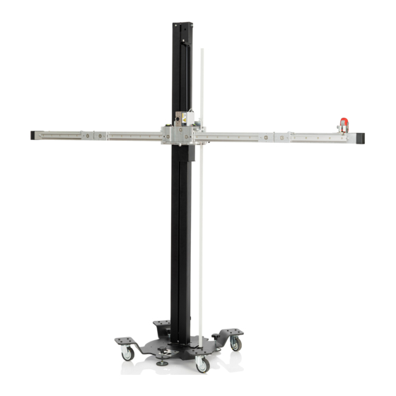
    Dénomination Référence Généralités Plaque de base 1 690 381 267 Le SCT 415 S52 peut être utilisé avec la plaque de base Barre de réglage 1 690 381 118 mobile sur différents emplacements de mesure. Il se Colonne 1 690 381 125 compose de la plaque de base, de la colonne, de la bar- Pied de réglage...
  • Page 57: Montage

    Montage | SCT 415 S52 | 57 Montage Tôle de butée ¶ Retirer la tôle de butée en haut et en bas. Plaque de base Monter la colonne sur la plaque de base Pour un montage aisé, fixer la colonne à plat sur la plaque de base.
  • Page 58: Tôle De Recouvrement

    58 | SCT 415 S52 | Montage Tôle de recouvrement Entretoise de règle de mesure ¶ ¶ Déplacer sur le côté la tôle de recouvrement et les Fixer l'entretoise de règle de mesure en haut et en bandes de caoutchouc.
  • Page 59: Monter L'aiguille

    Montage | SCT 415 S52 | 59 Monter l'aiguille 5.11 Barre de réglage ¶ 1. Défaire les vis à tôle. Fixer la barre de réglage 2. Fixer le couvercle de boîtier avec quatre vis à tôle. 1 Support 2 Fixation 3 Fixation du levier 4 Barre de réglage...
  • Page 60: Télémètre Laser

    60 | SCT 415 S52 | Montage 5.12 Télémètre Laser 5.13 Unité laser ¶ 1. Insérer les piles dans le télémètre. Monter l'unité laser 2. Fixer le télémètre sur son support. Lors de montage de grands panneaux de mesure, sortir au maximum le "télémètre laser", si nécessaire modifier la position du laser.
  • Page 61: Fixer La Barre De Réglage Dans Le Support De Barre De Réglage

    Montage | SCT 415 S52 | 61 5.15 Fixer la barre de réglage dans le sup- 5.16 Instructions au dos du panneau de mesure port de barre de réglage 1. Déposer la barre de réglage avec précaution et la Respecter les instructions pour les panneaux de positionner sur le support.
  • Page 62: Monter Le Grand Panneau De Mesure

    62 | SCT 415 S52 | Montage 5.17 Monter le grand panneau de mesure 5.18 Monter le petit panneau de mesure Abb. 5: Fixer le petit panneau de mesure au chariot 1 Crochet de retenue 2 Chariot 3 Petit panneau de mesure 1.
  • Page 63: Conditions Requises Pour L'emplacement De Mesure

    Conditions requises pour l'emplacement de mesure | SCT 415 S52 | 63 Conditions requises pour l'emplacement de mesu- Conditions d'environnement 6.1.1 Planéité de l'emplacement de mesure La planéité sur l'emplacement de mesure du produit SCT 415 S52 ne doit pas dépasser 1 mm. La planéité de la surface de positionne- ment du véhicule est de 10 mm.
  • Page 64: Utilisation

    SCT 415 S52 devant le véhicule. véhicule. 3. Orienter le produit SCT 415 S52 au milieu entre les marquages au sol gauche et droit F et E, utiliser ici la fenêtre de contrôle dans la plaque de base com- me référence.
  • Page 65: 51 8.3 Rectifier La Position Du Sct 415 S52

    Utilisation | SCT 415 S52 | 65 90° Abb. 8: Orienter par rapport au marquage au sol Rectifier la position du SCT 415 S52 1 Rayon laser 2 Marquage au sol 3 Alignement véhicule 1. Déverrouiller le dispositif de serrage à excentrique.
  • Page 66: Ajuster Sct 415 S52 Sur Le Plan Médian

    1. Positionner le produit SCT 415 S52 devant le véhicu- 2. Fixer P-Assist S5 sur le logement laser A et bloquer avec le crochet. Abb. 10: Ajuster le produit SCT 415 S52 au milieu devant le véhicule 1 Ligne laser 2 Emblème du constructeur 3 Antenne Si l'emblème du constructeur et l'antenne ne se...
  • Page 67: 51 8.6 Orienter Le Support De Précision

    à poignée-étoile. Pour le calibrage statique de la caméra de pare-bri- se, le produit SCT 415 S52 doit être ajusté selon le niveau pour l'angle de roulis et le niveau pour l'angle de tangage.
  • Page 68: Fixer Le Support De Mètre Ruban

    3. Serrer la vis de fixation. 4. Poser le mètre ruban dans le support de mètre ru- ban et le fixer avec la vis moletée. Abb. 15: Orienter le produit SCT 415 S52 avec l'aide au réglage 1 Aide au réglage 8.10 Régler la hauteur du panneau de...
  • Page 69: Lire La Hauteur

    Utilisation | SCT 415 S52 | 69 8.11 Lire la hauteur Abb. 16: Lire la hauteur 1 Règle 2 Aiguille 3 Poignée de blocage 4 Vis de fixation 1. Desserrer la vis de fixation de la règle de mesure. 2. Faire descendre la règle jusqu'au sol.
  • Page 70: Sct 415 S52

    70 | SCT 415 S52 | Entretien Entretien Pièces de rechange et d'usure Contrôle 9.5.1 Panneaux de mesure Faire contrôler le produit SCT 415 S52 une fois par an pour Dénomination Fig. Référence garantir la précision de son réglage. 1 690 382 608...
  • Page 71: Bras Support

    Entretien | SCT 415 S52 | 71 9.5.2 SCT 415 S52 Dénomination Position Référence P-Assist S5 1 690 381 124 Chariot gauche 1 690 381 123 Chariot droit 1 690 381 127 Barre de réglage 1 690 381 118 Mètre-ruban droite 1 693 740 649 Mètre-ruban gauche...
  • Page 72: Plaque De Base

    72 | SCT 415 S52 | Entretien 9.5.4 Plaque de base 9.5.5 Coulisse / Support règle / Règle de mesure Dénomination Position Référence Kit de pièces 1 690 381 149 Kit de pièces 1 690 381 208 Plaque de base 1 690 381 267 Dénomination...
  • Page 73: 55 9.5.6 Unité De Positionnement

    Entretien | SCT 415 S52 | 73 9.5.6 Unité de positionnement 9.5.8 Support de mètre-ruban Dénomination Position Référence Support de mètre- – 1 690 381 206 ruban 9.5.9 Entretoise Dénomination Position Référence Unité de positionne- 1 690 381 281 ment 9.5.7...
  • Page 74: 56 9.5.11 Dispositif De Positionnement

    74 | SCT 415 S52 | Entretien 9.5.10 P-Assist S5 /Support barre de réglage 9.5.13 Télémètre à laser Dénomination Position Référence Télémètre à laser 1 693 770 567 Entretoise de télémètre à 1 690 381 253 laser Coulisse pour télémèt- 1 690 381 279 re à...
  • Page 75: 10. Caractéristiques Techniques

    Caractéristiques techniques | SCT 415 S52 | 75 10. Caractéristiques tech- niques 10.1 Dimensions et poids SCT 415 S52 Fonction Spécification Dimensions h x l x p 1800 x 2000 x 600 mm Poids 53 kg 10.2 Dimensions et poids P-Assist Fonction Spécification Dimensions h x l x p 950 x 290 x 260 mm Poids 4,3 kg 10.2.1 Instrument de mesure Fonction Spécification...
  • Page 76 Simboli utilizzati Esempio di allineamento Nella documentazione Correggere la posizione SCT 415 S52 1.1.1 Indicazioni di avvertimento – struttura Allineare SCT 415 S52 con il piano mediano e significato longitudinale del veicolo 1.1.2 Simboli nella presente Allineamento con il dispositivo di documentazione xxx...
  • Page 77: Simboli Utilizzati

    ¶ La parola chiave rappresenta un indice per la probabili- SCT 415 S52 può essere messo in esercizio solo da per- tà di insorgenza e la gravità del pericolo in caso di man- sonale specializzato. In caso di uso non conforme, errato...
  • Page 78 Diritti d'autore la coordinazione e la sorveglianza di un tecnico in conformi- Il software e i dati sono proprietà di Bosch GmbH o del tà ai regolamenti in vigore in materia di elettrotecnica. relativo fornitore e sono protetti da leggi sui diritti d'autore,...
  • Page 79: Avvertenze Di Sicurezza

    Avvertenze di sicurezza | SCT 415 S52 | 79 Avvertenze di sicurezza Collaudi (esempio per la Germania): Il proprietario/gestore dell'officina deve provvedere affin- Pericolo di lesioni, pericolo di schiac- ché venga controllato da un elettricista o sotto la sor- ciamento...
  • Page 80: Descrizione Del Prodotto

    Descrizione del prodotto Fornitura Denominazione Numero Dati generali d'ordine Grazie alla piastra di base, SCT 415 S52 può essere Piastra di base 1 690 381 267 impiegato in diverse postazioni di misurazione. È costi- Asta di regolazione 1 690 381 118...
  • Page 81 Montaggio | SCT 415 S52 | 81 Montaggio Piastra di arresto ¶ Rimuovere la piastra di arresto in alto e in basso. Piastra di base Montare il palo sulla piastra di base Per facilitare il montaggio, fissare il palo sulla piast- ra di base in modo orizzontale.
  • Page 82 82 | SCT 415 S52 | Montaggio Lamiera di copertura Supporto distanziatore righello ¶ ¶ Spingere lateralmente la lamiera di copertura e le Fissare il supporto distanziatore del righello in alto e strisce di gomma. in basso. Righello ¶ Inserire il righello nella piastra di base e fissare con 1 Lamiera di copertura vite e dado.
  • Page 83 Montaggio | SCT 415 S52 | 83 Applicare gli indicatori 5.11 Asta di regolazione ¶ 1. Allentare le viti autofilettanti. Applicare l'asta di regolazione 2. Applicare l'indicatore e fissare con le viti autofilettanti. 1 Supporto 2 Fissaggio 3 Fissaggio leva 4 Asta di regolazione 1.
  • Page 84 84 | SCT 415 S52 | Montaggio 5.12 Telemetro laser 5.13 Unità laser ¶ 1. Posizionare le batterie nel telemetro. Applicare l'unità laser 2. Fissare il telemetro nel supporto. In caso di montaggio di pannelli di misurazione di grandi dimensioni, estrarre il supporto distanziato- re "telemetro laser"...
  • Page 85 Montaggio | SCT 415 S52 | 85 5.15 Fissare l'asta di regolazione nel rela- 5.16 Istruzioni retro pannello di misurazi- tivo supporto 1. Appoggiare con cura l'asta di regolazione e posizio- narla nel supporto. Attenersi alle istruzioni per il pannello di misurazio- 2.
  • Page 86 86 | SCT 415 S52 | Montaggio 5.17 Montaggio del pannello di misurazio- 5.18 Montaggio del pannello di misurazio- ne grande ne piccolo Abb. 5: Fissare il pannello di misurazione piccolo sul corsoio 1 Fune di sicurezza 2 Corsoio 3 Pannello di misurazione piccolo 1.
  • Page 87: Condizioni Ambientali

    Requisiti postazione di misurazione | SCT 415 S52 | 87 Requisiti postazione di P-Assist misurazione (comprese nella fornitura a seconda della versione ordinata.) ¶ Spostare o trasportare solo tramite profilo del montante. Condizioni ambientali 6.1.1 Planarità postazione di misurazione Non trasportare dal dispositivo di regolazione o dal sup- La planarità...
  • Page 88 Esempio di allineamento Allineamento 1. Eseguire i contrassegni sul pavimento con il filo a piombo sul veicolo e poi allineare SCT 415 S52. I valori specifici per l'allineamento esatto di 2. Applicare i contrassegni per l'allineamento sul SCT 415 S52 sono descritti nelle corrispondenti pavimento.
  • Page 89 Uso | SCT 415 S52 | 89 90° Abb. 8: Allineare in base al contrassegno sul pavimento Correggere la posizione SCT 415 S52 1 Fascio laser 2 Contrassegno sul pavimento 3 Allineamento veicolo 1. Sbloccare i morsetti eccentrici. 2. Correggere la posizione.
  • Page 90 1. Posizionare il SCT 415 S52 davanti al veicolo. 2. Fissare il P-Assist S5 sull'alloggiamento laser A e fissare con fune di sicurezza. Abb. 10: Allineare il SCT 415 S52 davanti al veicolo, centralmente 1 Linea laser 2 Emblema del produttore 3 Antenna Abb.
  • Page 91 Misurare la distanza con il laser con le viti a stella. Per la calibrazione statica della telecamera installata sul parabrezza il SCT 415 S52 deve essere allineato rispetto alla livella per l'angolo di rullaggio e alla livella per l'angolo di passo.
  • Page 92 3. Serrare la vite di fissaggio. 4. Applicare il metro a nastro nel relativo supporto e fissare con vite zigrinata. Abb. 15: Allineamento di SCT 415 S52 con lo strumento di rego- lazione 1 Strumento di regolazione 8.10 Impostazione dell'altezza del pannel- lo di calibrazione 1.
  • Page 93: Leggere L'altezza

    Uso | SCT 415 S52 | 93 8.11 Leggere l'altezza Abb. 16: Leggere l'altezza 1 Righello 2 Indicatore 3 Manopola di bloccaggio 4 Vite di fissaggio 1. Allentare la vite di regolazione del righello. 2. Abbassare il righello fino al pavimento.
  • Page 94: Manutenzione Preventiva

    È possibile ordinare il dispositivo di controllo per il test di SCT 415 S52 e del laser presso il produttore. 1) Compreso nella fornitura a seconda della versione ordinata 2) Da utilizzare solo con braccio di sostegno Pulizia Pulire solo con panni morbidi e privi di pelucchi.
  • Page 95 Manutenzione preventiva | SCT 415 S52 | 95 9.5.2 SCT 415 S52 Denominazione Posizione Numero d'ordine P-Assist S5 1 690 381 124 Corsoio sinistro 1 690 381 123 Corsoio destro 1 690 381 127 Asta di regolazione 1 690 381 118...
  • Page 96 96 | SCT 415 S52 | Manutenzione preventiva 9.5.4 Piastra di base 9.5.5 Carrello / Supporto righello / Righello Denominazione Posizione Numero d'ordine Kit di componenti 1 690 381 149 Kit di componenti 1 690 381 208 Piastra di base...
  • Page 97 Manutenzione preventiva | SCT 415 S52 | 97 9.5.6 Unità di posizionamento 9.5.8 Supporto metro a nastro Denominazione Posizione Numero d'ordine Supporto metro a – 1 690 381 206 nastro 9.5.9 Supporto distanziatore Denominazione Posizione Numero d'ordine Unità di posiziona-...
  • Page 98 98 | SCT 415 S52 | Manutenzione preventiva 9.5.10 P-Assist S5 / Supporto asta di regolazione 9.5.13 Misuratore distanza laser Denominazione Posizione Numero d'ordine Misuratore distanza la- 1 693 770 567 Supporto distanziato- 1 690 381 253 re per misuratore distan-...
  • Page 99: Dati Tecnici

    Dati tecnici | SCT 415 S52 | 99 10. Dati tecnici 10.1 Dimensioni e pesi SCT 415 S52 Funzione Specifiche Dimensioni (alt. x largh. x prof.) 1800 x 2000 x 600 mm Peso 53 kg 10.2 Dimensioni e pesi P-Assist...
  • Page 100 100 | SCT 415 S52 | jp – 目次 操作 8.1 位置調整 使用される記号 8.2 位置調整の例 1.1 ドキュメンテーションの内容 8.3 SCT 415 S52位置を修正します 1.1.1 警告事項 – 構成ならびに意味 8.4 SCT 415 S52を車両の縦方向の中心面に合わせ 1.1.2 記号 - 名称ならびに意味 る 1.2 製品上 8.5 位置決め装置に合わせる 8.6 精密ホルダーの配置 重要な注意事項 8.7 レーザーで距離を測定する 2.1 正しい使用法 8.8 巻尺ホルダーの固定 2.3 協定...
  • Page 101: 記号 - 名称ならびに意味

    警告注意事項はユーザー或いは周囲の人員への危険につい ーの安全安全遵守、機械の損傷回避、並びに Bosch製 て警告を与えます。 警告注意事項はさらに危険の帰結及び防 品の取り扱いに関する不明な点やそれに伴う危険を未然に 止措置を記載しています。 警告注意事項は次ぎの構成から成 回避することができます。Bosch製品を第三者に渡す ります: 場合は、取扱説明書だけではなく安全に関する注意と正し い操作に関する情報も必ず一緒に渡してください。 警告記号 正しい使用法 注意語 – 危険の種類及び発生源! ¶ 規定措置及び注意事項に従わない場合の危険に SCT 415 S52は、自動車のセンサーやカメラの静的キャ よる帰結 リブレーションにのみ使用されます。車両メーカー固有 ¶ 危険回避のための措置及び注意事項 の修理マニュアルおよびサービスマニュアルに従いま す。その他の用途での使用は、装置の正しい使用方法と 注意語は無視した場合の危険の発生確率ならびに重大度を示し は認められません。 ¶ ます: SCT 415 S52の使用は、研修を受けた専門技術者だけに 限られます。メーカー (Bosch GmbH) は、装置の 注意用語...
  • Page 102 102 | SCT 415 S52 | 重要な注意事項 ¶ 保証 メンテナンスおよび修理作業後は常に安全装置を取り付 け、点検します。 リリースされていないハードウェアやソフトウェアを使用 ¶ メンテナンスおよび修理作業が終了次第、組み立ておよ すると、本製品の変更につながる可能性があります。従っ び安全装置を点検します。 て該当のハードウェアやソフトウェアが取り除かれたり、 ¶ クロスビーム、リフレクター ユニットおよびレーザー または削除された場合でも、弊社は保証および損害賠償の プロジェクターをキャリブレーションし、調整します。 責任は負いません。 固定されたボルトを取り外したり調整することは禁止さ れています。この場合、メーカーの工場内でしか調整は 弊社の製品を変更することは禁止されています。弊社の製 できなくなります。 品には、純正アクセサリと純正部品のみ使用してくださ ¶ ミラーユニット、リファレンスボード、カメラキャリブ い。それ以外の部品を使用した場合、保証が無効となりま レーションボードまたはクロスバーで支えないでくださ す。 い。 工場所有者/工場責任者の義務 ユーザーサークル 工場所有者/工場責任者には事故、職業病、および作業に伴 本製品の使用は、研修を受けた担当の技術者だけに限られ う健康被害を防ぐ対策を取り、さらに人間工学に配慮した ます。未研修の従業員、見習い中の従業員または職業訓練...
  • Page 103 ¶ 車両のフロント、リアおよびサイドが測定ステーション 点検の際、関連する電気工学の規定を遵守してくださ から動いて落ちないように固定します。 ¶ い。 増強ツールを使用しないでください。 ¶ 取扱説明書に従って運搬、操作してください。 同業組合から要求がある場合、該当の項目が記載された 検査表を作成します。 関連資料 強力な磁石により危険! SCT 415 S52のすべての文書: SCT 415 S52の強力な磁石によるペースメーカー 文書 注文番号 への影響が危惧されます。 ¶ CE適合宣言書: ペースメーカーがある場合、SCT 415 S52の磁 P-Assist S5 (レーザーモジュ 1 690 386 037 石に近づかないで下さい。 ール) 取扱説明書 P-Assist S5 (レー...
  • Page 104 104 | SCT 415 S52 | 製品詳細 製品詳細 同梱品 名称 注文番号 全般 SCT 415 S52は可動的なベースプレートを使用し、 さまざまな ベースプレート 1 690 381 267 測定現場で使用できます。 ベースプレート、 コラム、 調整ロッ ドお 調整ロッド 1 690 381 118 コラム 1 690 381 125 よびP-Assist S5で構成されています。 設置脚 1 693 740 663...
  • Page 105 取付け | SCT 415 S52 | 105 取付け ストッププレート ¶ 上下のスト ッププレートを取り外します。 ベースプレート ベースプレートへのコラム取付け 取り付けが簡単なコラムをベースプレートに固定します。 ベースプレートのロックハンドル位置に注意してください。 スト ッププレート 間隔管 ¶ 間隔管の取外し 1 間隔管 2 カバープレート 3 ネジ 位置 取り付け方法 数 サイズ [mm] M6 x 10 Robert Bosch GmbH 1 690 386 051 2020-10-22...
  • Page 106 106 | SCT 415 S52 | 取付け カバープレート 測定定規のホルダー ¶ ¶ カバープレート とラバースト リ ップを片側に押します。 測定定規のホルダー上下を固定します。 測定定規 ¶ 測定定規をベースプレートに通し、 ボルト とナッ トで固定し 1 カバープレート ます。 2  ラバースト リ ップ スペーサー 方向に注意してください。 1 ナッ ト M3 2 ボルト M3 1 スペーサー 1. スペーサーを取り付けます...
  • Page 107 1 タッピングネジ 2 ポインター 4. 調整ロッ ドをマウン トの中央に合わせます。 5. 調整ロッ ドに接触するまでグラブネジを締め、 両側をナッ ト 5.10 マウント で固定します。 ¶ マウン トを取り付けます。 6. 固定レバーで固定します。 1 グラブネジ 2 ナッ ト 1 ローレッ トネジ 2 ナッ ト M6 Robert Bosch GmbH 1 690 386 051 2020-10-22...
  • Page 108 108 | SCT 415 S52 | 取付け 5.12 レーザーレンジファインダー 5.13 レーザーユニッ ト ¶ 1. レンジファインダーにバッテリーを挿入します。 レーザーユニッ トを取り付けます 2. レンジファインダーをマウントに固定します。 大ボードを取り付ける場合は、 ホルダー"レーザーレンジフ ァインダー"を最大限に引き出し、 必要に応じてレーザーの 位置を変えてください。 5.14 P-Assist S5/調整ロッ ドマウント 1. P-Assist S5と調整ロッ ドマウン トを取り付けます 1 調整ロッ ドマウン ト 2 穴 3 リベッ ト...
  • Page 109 1 690 382 617 す。 1 690 382 642 (ご注文の仕様によっては同梱品に含まれます) 調整ロッ ドのマウン ト配置方向に注意してください。 Abb. 2: 調整ロッ ドマウン トの精密測定バー 1 調整ロッ ドマウン ト 2 調整ロッ ド 3 安全ピン 4 ボール保護 5 調整ロッ ドマウン トの開口部 Robert Bosch GmbH 1 690 386 051 2020-10-22...
  • Page 110 110 | SCT 415 S52 | 取付け 5.17 大ボードの取付け 5.18 小ボードの取付け Abb. 5: キャ リ ッジへの小ボード固定 1 安全ロープ 2 キャ リ ッジ 3 小ボード 1. 小ボードをキャ リ ッジに固定します。 Abb. 3: 大ボードの固定 2. 安全ロープで固定します。 1 位置 1 2 位置 2 3 大ボードの保持アーム 1) ボード: ボードが平らに置かれているか注意してください ¹) ご注文の仕様によっては同梱品に含まれます...
  • Page 111 測定場所の前提条件 | SCT 415 S52 | 111 測定場所の前提条件 P-Assist (ご注文の仕様によっては同梱品に含まれます) 環境条件 ¶ 必ずストラットプロフィールで持ち上げ移動させます。 6.1.1 測定場所の平面度 SCT 415 S52の測定場所の平面度は1 mmを超えないこと。車 調整装置やレーザー台で持ち上げないで下さい。 両の取付け面の平面度は10 mmです。 平らでない場合、転倒の危険。 6.1.2 試験ステーションの条件 位置決めユニッ ト 測定所の運営は自動車メーカーのガイドラインに従うこ と。 作業エリアに直射日光が差し込まないこと。 十分な照明があることを確認すること。 パネルの背景は明るすぎないこと。 輸送 SCT 415 S52 1. 調整ロッドを最も低い位置にします。 2. 可動プレートを中央の位置にします。 3. 偏心クランプをロックします。 4. 最も高い位置に設置脚を調整します。 5. 測定定規を上昇位置に固定します。...
  • Page 112 112 | SCT 415 S52 | 操作 操作 位置調整の例 位置調整 1. 車両につけた垂球で地面にマーキングし、 それから SCT 415 S52を配置します。 SCT 415 S52を正確に配置するための特定値は、 対応す 2. 地面に配置用のマークを付けます。 SCT 415 S52を車両の る車両メーカーの "修理マニュアル" に記載されています。 前に配置します。 3. ベースプレートの点検窓を基準にし、 SCT 415 S52を左右 の地面マークFとEの中央に合わせます。 4. ベースプレートの両方のポインターがG-Hラインを指すま で、 ベースプレートを同時にゆっ く り動かします。 Abb. 6: 垂球の正面図 Abb. 7: 垂球の側面と背面図 1 690 386 051 2020-10-22...
  • Page 113 操作 | SCT 415 S52 | 113 90° Abb. 8: 地面のマークに合わせた配置 SCT 415 S52位置を修正します 1 レーザー光線 2 地面のマーク 3 車両配置 1. 偏心クランプをアンロックします。 2. 位置を修正します。 3. 偏心クランプをロックします。 1 偏心クランプ Robert Bosch GmbH 1 690 386 051 2020-10-22...
  • Page 114 114 | SCT 415 S52 | 操作 SCT 415 S52を車両の縦方向の中心面に 4. SCT 415 S52は、 車両フロン トのメーカーのエンブレムと 合わせる アンテナがレーザー線でマークされるように調整します。 " (レーザーモジュール P-Assist S5使用時のオプション) SCT 415 S52は車両前に配置しています。 SCT 415 S52を正確に配置するための特定値は、 対応する 車両メーカーの "修理マニュアル" に記載されています。 以下は配置例です 1. SCT 415 S52を車両の前に配置します。 2. P-Assist S5をレーザースキャンに取り付け、 安全ロープで 固定します。 Abb. 10: SCT 415 S52の車両前中央配置 1 レーザー線 2 メーカーのエンブレム 3 アンテナ メーカーのエンブレムとアンテナが車両縦中心面にない Abb. 9: レーザースキャン AのP-Assist S5 場合は、...
  • Page 115 1 レーザーレンジファインダー 2 水準器 3 ホイールセンタ リングピン 4 設置脚 1. ホイールセンタ リングピン (3) をホイールセンターに配置 します。 2. 設置脚 (4) で水準器 (2) を調整します。 Abb. 11: 精密ホルダーの配置 3. レーザーレンジファインダー (1) の距離を読み取ります。 1 精密ホルダー 2 ロール角の水準器 3 ピッチ角の水準器 4 設置脚 5 巻尺ホルダー ¶ 巻尺ホルダーを調整ロッ ドに固定します。 Robert Bosch GmbH 1 690 386 051 2020-10-22...
  • Page 116 116 | SCT 415 S52 | 操作 巻尺ホルダーの固定 設定サポートでのSCT 415 S52 位置調整 設定サポートは別売付属品として用意されています。 1. 設定サポートをスターノブスク リ ューの上に置きます。 2. 精密ホルダーの水準器に基づいて、 SCT 415 S52を設定 サポートに合わせます。 Abb. 13: 巻尺ホルダーの固定 1 ロックスク リ ュー 2 ローレッ トネジ 1. ロックスク リ ューを外します。 2. 巻尺ホルダーを調整ロッ ドに取り付けます。 3. ロックスク リ ューを締めます。...
  • Page 117 操作 | SCT 415 S52 | 117 8.11 高さの読み取り Abb. 16: 高さの読み取り 1 測定定規 2 ポインター 3 ロックハンドル 4 ロックスク リ ュー 1. 測定定規のロックスク リ ューを外します。 2. 測定定規を床まで下げます。 Abb. 17: 床上の測定定規 1 測定定規 3. ポインターで高さを読み取ります。 4. 測定定規のロックスク リ ューを固定します。 Robert Bosch GmbH 1 690 386 051 2020-10-22...
  • Page 118 118 | SCT 415 S52 | メンテナンス メンテナンス 予備部品と消耗部品 点検 9.5.1 ボード 1年毎にSCT 415 S52を点検し、 設定精度を確認します。 名称 図 注文番号 ボードの磁石を点検し、 必要に応じてク リーニングします。 1 690 382 608 1) 2) ボードが損傷した場合、 交換します。 スバル 2S 適切な測定装置はリファレンスボード、 リフレクター ユニッ トお よびキャ リブレーションボードの相対的な平行位置を点検す るために必要です。 メーカー承認のラインレーザーを推奨しま 1 690 382 590 1) 2) スバル...
  • Page 119 メンテナンス | SCT 415 S52 | 119 9.5.2 SCT 415 S52 名称 位置 注文番号 P-Assist S5 1 690 381 124 左側キャリッジ 1 690 381 123 右側キャリッジ 1 690 381 127 調整ロッド 1 690 381 118 右側巻尺 1 693 740 649 左側巻尺 1 693 740 650 コラム...
  • Page 120 120 | SCT 415 S52 | メンテナンス 9.5.4 ベースプレート 9.5.5 スライダー/測定定規マウント/ 測定定規 名称 位置 注文番号 部品キット 1 690 381 149 部品キット 1 690 381 208 ベースプレート 1 690 381 267 名称 位置 注文番号 スライダー 1 690 382 280 測定定規 1 690 381 255 マウント...
  • Page 121 1 690 381 206 9.5.9 スペーサー 名称 位置 注文番号 位置決めユニット 1 690 381 281 9.5.7 設定サポート 名称 位置 注文番号 スペーサー 1 690 382 669 名称 位置 注文番号 設定サポート 1) 1 690 381 210 ¹) ご注文の仕様によっては同梱品に含まれます Robert Bosch GmbH 1 690 386 051 2020-10-22...
  • Page 122 122 | SCT 415 S52 | メンテナンス 9.5.10 P-Assist S5/調整ロッ ドマウント 9.5.13 レーザーレンジファインダー 名称 位置 注文番号 レーザーレンジファイ 1 693 770 567 ンダー レーザーレンジファイン 1 690 381 253 ダー用ホルダー レーザーレンジファイン 1 690 381 279 名称 位置 注文番号 ダー用キャリッジ P-Assist S5 1 690 381 124 調整ロッドマウント...
  • Page 123 技術データ | SCT 415 S52 | 123 10. 技術データ 10.1 SCT 415 S52の寸法と重量 機能 仕様 寸法:高さx幅x奥行 1800 x 2000 x 600 mm 重量 53 kg 10.2 P-Assistの寸法と重量 機能 仕様 寸法:高さx幅x奥行 950 x 290 x 260 mm 重量 4.3 kg 10.2.1 測定装置 機能 仕様 巻尺 垂球 200 g 10.2.2...
  • Page 124 Robert Bosch GmbH Diagnostics Franz-Oechsle-Straße 4 73207 Plochingen GERMANY www.bosch.com bosch.prueftechnik@bosch.com 1 690 386 051 | 2020-10-22...

Table des Matières