Table des Matières
Publicité
Les langues disponibles
Les langues disponibles
Liens rapides
Instructions for use and installation
GB
Cooker Hood
Istruzioni per l'uso e l'installazione
IT
Cappa
Mode d'emploi et installation
FR
Hotte de Cuisine
Bedienungsanleitung und Installation
DE
Dunstabzugshaube
Kullan m ve montaj talimatlar
TR
Davlumbaz
Uživatelská Pøíruèka
CZ
Odsava par
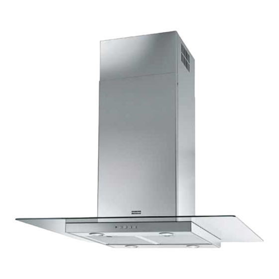
FGL 915 I XS
FGL 915 I BK/XS
Publicité
Table des Matières

Manuels Connexes pour Franke FGL 915 I XS


Sommaire des Matières pour Franke FGL 915 I XS
- Page 1 Instructions for use and installation Cooker Hood Istruzioni per l’uso e l’installazione Cappa Mode d’emploi et installation Hotte de Cuisine Bedienungsanleitung und Installation Dunstabzugshaube Kullan m ve montaj talimatlar Davlumbaz Uživatelská Pøíruèka Odsava par FGL 915 I XS FGL 915 I BK/XS...
-
Page 2: Table Des Matières
INDEX RECOMMENDATIONS AND SUGGESTIONS ........................3 CHARACTERISTICS ................................6 INSTALLATION..................................8 USE ...................................... 12 MAINTENANCE ................................... 13 INDICE CONSIGLI E SUGGERIMENTI............................14 CARATTERISTICHE................................17 INSTALLAZIONE ................................. 19 USO...................................... 23 MANUTENZIONE ................................24 SOMMAIRE CONSEILS ET SUGGESTIONS............................25 CARACTERISTIQUES................................. 28 INSTALLATION..................................30 UTILISATION .................................. -
Page 25: Conseils Et Suggestions
CONSEILS ET SUGGESTIONS Les instructions pour l’utilisation se réfèrent aux différents modèles de cet appareil. Par conséquent, certaines descriptions de caractéristiques particulières pourraient ne pas appartenir spécifiquement à cet appareil. INSTALLATION • En aucun cas le fabricant ne peut être tenu pour responsable d’éventuels dommages dus à... -
Page 26: Utilisation
• Si les instructions d’installation du plan de cuisson à gaz spécifient une distance supérieure à celle indiquée ci-dessus, veuillez impérativement en tenir compte. Toutes les normes concernant l’évacuation de l’air doivent être respectées. • Utiliser exclusivement des vis et des petites pièces du type adapté pour la hotte. -
Page 27: Entretien
• ATTENTION : les parties accessibles peuvent devenir très chaudes durant l’utilisation des appareils de cuisson. ENTRETIEN • Avant d’effectuer toute opération de nettoyage et d’entretien, éteindre ou débrancher l’appareil du secteur. • Nettoyer et/ou remplacer les filtres après le délai indiqué (danger d’incendie). -
Page 28: Caracteristiques
CARACTERISTIQUES Encombrement Min. Min. 650mm 500mm... - Page 29 Composants Réf. Q.té Composants du produit Corps de hotte comprenant : Commandes, Éclairage, Filtres Conduit télescopique constitué de : Conduit supérieur Conduit inférieur Conduit télescopique constitué de: 14.1 Panneau supérieur Panneau inférieur Bride de réduction ø 150 - 120 mm 14.1 Rallonge raccord de sortie de l’air Raccord de sortie de l’air...
-
Page 30: Installation
INSTALLATION Perçage Plafond/Étagère et Fixation Treillis PERÇAGE PLAFOND/ETAGERE • À l’aide d’un Fil à plomb, reporter sur le Plafond/Étagère de support le centre du Plan de Cuisson. • Poser contre le Plafond/Étagère le Gabarit de Perçage 21 fourni avec l’appareil, en faisant coïncider son centre avec le centre projeté... - Page 31 Fixation Treillis/Conduit Au cas où l’on souhaiterait régler la hauteur du treillis, suivre la marche ci-dessous : • Desserrer les vis métriques d’assemblage des deux parties fron- tales visibles par la partie avant ; • Régler la hauteur désirée du treillis et resserrer les vis précé- demment retirées, en ayant soin d’en placer 2 à...
- Page 32 Sortie de l’air version filtrante • Monter latéralement les rallonges du raccord 14.1 sur le rac- cord 15 ; • Placer le raccord 15 dans l’étrier de soutien 7.3 en le fixant avec les vis ; • Fixer l’étrier de soutien 7.3 en le fixant avec les vis à la partie supérieure.
-
Page 33: Branchement Electrique
Montage du panneau et fixation du corps de hotte Avant de fixer le corps de hotte au treillis : • Retirer les filtres à graisse du corps de hotte. • Retirer les éventuels filtres anti-odeur au charbon actif. • En passant par-dessous, fixer ensuite le corps de hotte au treil- lis, avec les 4 vis 12f fournies (M6 x 10). -
Page 34: Utilisation
UTILISATION Tableau des commandes TOUCHE VOYANT FONCTIONS T1 Vitesse Allumé Démarre le moteur en première vitesse. Coupe le moteur. T2 Vitesse Allumé Démarre le moteur en deuxième vitesse. T3 Vitesse Fixe Appuyée brièvement, démarre le moteur en troisième vitesse. Clignotant Appuyée pendant 2 secondes. -
Page 35: Entretien
ENTRETIEN Filtres anti-graisse NETTOYAGE FILTRES ANTI-GRAISSE METALLIQUES AUTOPORTEURS • Lavables au lave-vaisselle, ils doivent être lavés environ tous les 2 mois d’emploi ou plus fréquemment en cas d’emploi par- ticulièrement intense. • Retirer les filtres l’un aprés l’autre, en les poussant vers la par- tie arrière du groupe et en tirant simultanément vers le bas. - Page 72 Franke S.p.a. Via Pignolini,2 37019 Peschiera del Garda (VR) www.franke.it 991.0443.205_ver2 - 171123 - D002625_01...