Table des Matières

Publicité

Les langues disponibles
  • FR

Les langues disponibles

Liens rapides

IO-Modul uP N5951 / IO module uP N5951
Module IO uP N5951 / Modulo IO uP N5951
IO-module uP N5951
Installations- und Montageanleitung
Installation and mounting instructions
Notice d'installation et de montage
Manuale d'installazione e montaggio
Installatie- en montagehandleiding
D0087400
www.assaabloy.de
DE Seite
DE Seite
EN Page
EN Page
FR Page
FR Page
IT Page
NL Pagina 60
NL Pagina 98
The global leader in
door opening solutions
2
2
26
20
50
40
74

Publicité

Table des Matières
loading

Sommaire des Matières pour Assa Abloy uP N5951

  • Page 1 NL Pagina 60 IT Page NL Pagina 98 IO-Modul uP N5951 / IO module uP N5951 Module IO uP N5951 / Modulo IO uP N5951 IO-module uP N5951 Installations- und Montageanleitung Installation and mounting instructions Notice d’installation et de montage Manuale d’installazione e montaggio...
  • Page 2 Weiterveräußerung mit dem Produkt weiter. Hi-O Technology™ ist ein eingetragenes Warenzeichen der ASSA ABLOY-Gruppe. Open Source Lizenzen ASSA ABLOY Sicherheitstechnik GmbH hält den Quellcode der im Rahmen von Open Source Lizenzen genutzten Software (zum Beispiel FreeRTOS™, newlib, lwIP) auf Anfrage bereit: http://www.assaabloy.com/com/global/opensourcelicense/...
  • Page 3: Table Des Matières

    Inhaltsverzeichnis Produktinformation........4 OneSystem IO-Modul uP ........... . . 4 Der Hi-O Technology™-Bus .
  • Page 4: Produktinformation

    Produktinformation OneSystem IO-Modul uP Das OneSystem IO-Modul uP (Abb. 1) ist ein IO-Modul zur Verbindung von Hi-O-Technology Produkten (zum Beispiel den OneSystem Schlössern mit konventionellen elektronischen Komponenten) in Türsystemen (zum Beispiel Zutrittskontroll- und Brandmeldeanlagen). Das OneSystem IO-Modul uP eignet sich zum Einbau in einer Unterputzdose. Abb.
  • Page 5: Der Hi-O Technology™-Bus

    Der Hi-O Technology™-Bus Der Hi-O Technology™-Bus (Highly Intelligent Opening) ist ein CAN-Netzwerk-Bus zur Verbindung von elektronischen Komponenten (Geräten) in Türsystemen (separate Anleitung D00873 OneSystem Hi-O Technology™ Verkabelung). Es dient zur Steuerung jeweils einer Tür. Die Zustandsüberwachung und der Informations- austausch zwischen den einzelnen Geräten erfolgen über den CAN-Bus. www.assaabloy.de Auf eine zentrale Logiksteuerung kann verzichtet werden, da jedes Gerät eine Lösungen /...
  • Page 6 Abb. 2 : Komponenten auf den Platinen Status Betrieb Offline blinkt blinkt Produktinformation...
  • Page 7: Anschlüsse

    Anschlüsse Anschlussbuchse für Service Drehschalter zum Einstellen der Geräte Ausgangsbelegung Hi-O Technology Anschluss 2 potentialfreie Ausgänge DIP-Schalter 1 und 2 SYSCON7 für Open Collector Ausgänge Hi-O Technology Jumper 1 und 2 SYSCON4-Anschluss vier digitale Eingänge und Anschluss für eine Brandmeldeanlage Achtung! Gefahr der Zerstörung, wenn Eingänge potentialbehaftet angesteuert werden: Die digitalen Eingänge (Abb.
  • Page 8: Hinweise

    Hinweise Zu dieser Anleitung Diese Anleitung ist für Elektrotechniker und entsprechend geschultes Personal geschrieben. Lesen Sie diese Anleitung, um das Gerät sicher zu installieren, zu betreiben und die zulässigen Einsatzmöglichkeiten, die es bietet, auszunutzen. Zugehörige Anleitungen · D00873XX OneSystem Hi-O-Verkabelung Bedeutung der Symbole Gefahr! Sicherheitshinweis: Nichtbeachtung führt zu Tod oder schwerer Verletzung.
  • Page 9: Sicherheitshinweise

    Sicherheitshinweise Achtung! Eine ungeschützte Verkabelung kann manipuliert werden: Über die Verkabe- lung werden die elektronischen Türkomponenten miteinander verbunden und gesteuert. Die Verkabelung muss zum Schutz vor Manipulationen und Störungen geschützt verlegt werden und darf von außen nicht zugänglich sein. Sachschaden durch Verbindung mit USB-Geräten: Die Anschlussbuchse am Ge- häusedeckel (Abb.
  • Page 10: Begriffserklärung

    Begriffserklärung Bezeichnung Beschreibung Terminieren Ein Hi-O Technology™-Bus muss mit einem Abschlusswiderstand versehen wer- den, der den Bus terminiert. Fehlt der Abschlusswiderstand kann die Datenüber- tragung gestört sein. Hi-O Technology™ Der Hi-O Technology™-Bus (Highly Intelligent Opening) ist ein CAN-Bus zur Ver- bindung von elektronischen Komponenten (Geräten) in Türsystemen. Er dient zur Steuerung jeweils einer Tür, der Zustandsüber wachung und dem Informa- tionsaustausch zwischen den einzelnen Geräten (separate Anleitung D01021xx ®...
  • Page 11: Bestimmungsgemäßer Gebrauch

    Bestimmungsgemäßer Gebrauch ® Das OneSystem  IO-Modul N5951 (IO-Modul) ist zur digitalen Verbindung von OneSystem ® -Schlössern über Hi-O Technology™ geeignet. Es dient dabei als Verbindung zu konventionellen Geräten, zum Beispiel: · Zutrittskontrolle, · bauseitige Schleusensteuerungen oder · Überwachungssteuerungen. An den potentialbehafteten digitalen Eingängen können externe Steuerungen und Ansteuerkontakte angeschlossen werden.
  • Page 12: Installation

    Installation Anschlüsse Hi-O Anschlüsse Beschreibung CAN H weiße Ader CAN L braune Ader VB + grüne Ader VB – gelbe Ader Eingänge Beschreibung In 1 Die digitalen Eingänge (5 – 10) dürfen ausschließlich durch In 2 potentialfreie Kontakte In 3 (Freigabetaster, Relaiskontakt) angesteuert werden.
  • Page 13 DIP-Schalter Position Auswirkung Abschlusswiderstand kein Abschlusswiderstand Hi-O-Gruppe 1 Hi-O-Gruppe 0 SYSCON4 Beschreibung VB + CAN H CAN L VB – SYSCON7 Beschreibung Ausgang 3 Schwarz Open-Collector 7 Ausgang 3 Ausgang 5 Grau Open-Collector 6 Vcc 5 Ausgang 5 4 Ausgang 6 Ausgang 6 Braun Open-Collector 3 Ausgang 4...
  • Page 14: Anschluss Der Brandmeldeanlage

    Anschluss der Brandmeldeanlage Jumper 1 und Jumper 2 Beschreibung kein Brandmeldealarm Jumper gesetzt lokaler Anschluss Jumper nicht gesetzt zentraler Anschluss Jumper nicht gesetzt Installation...
  • Page 15: Montage

    Montage Montagevorbereitung Stellen Sie vor der Montage folgende Punkte sicher: Voraussetzungen · Die Planung ist abgeschlossen. · Die Hi-O-Gruppenfunktion und die erforderlichen Abschlüsse sind festgelegt und die DIP-Schalter-Positionen korrekt eingestellt. · Die Brücke auf den Pins (Jumper) ist korrekt gesetzt. ·...
  • Page 16: Eingänge Und Ausgänge

    Eingänge und Ausgänge Drehschalter - Konfiguration der Ein- und Ausgänge Position Funktion Eingänge Drückersteuerung / Monitoring Externe Freigabe Externer Türkontakt Drückersteuerung Zylinder Externe Freigabe Externer Türkontakt Drückersteuerung Zuko / Zylinder Externe Freigabe Externer Türkontakt Motorschloss Zuko Externe Freigabe Externer Türkontakt Motorschloss Zuko / Zylinder Externe Freigabe Externer Türkontakt...
  • Page 17 Zentralverriegelung Zentralverriegelung Zentralverriegelung Zentralverriegelung Brandmeldung Zentralverriegelung Brandmeldung Zentralverriegelung Brandmeldung Zentralverriegelung Außentürdrücker betätigt Türdrücker gekoppelt Tür geschlossen Zylinder Außentürdrücker betätigt Türdrücker gekoppelt Tür geschlossen Innentürdrücker betätigt Außentürdrücker betätigt Türdrücker gekoppelt Tür geschlossen Innentürdrücker betätigt Ansteuerung Türantrieb Entriegelt Tür geschlossen Brandmeldung Ansteuerung Türantrieb Entriegelt Tür geschlossen Brandmeldung Ansteuerung Türantrieb Entriegelt...
  • Page 18: Eingänge

    Eingänge Input „IN1“ – Externe Freigabe An den Eingang kann ein Freigabetaster (oder anderer potentialfreier Ansteuer- kontakt) angeschlossen werden. Je nach angeschlossenen Hi-O Technology™- Geräten aktiviert der Ansteuerkontakt unterschiedliche Prozesse: · ein Motorschloss fährt den Riegel / die Riegel ein, · ein Kupplungsschloss koppelt den Außentürdrücker an, ·...
  • Page 19 Input „IN3“ – Zentralverriegelung An den Eingang kann der Ansteuerkontakt einer Zentralverriegelung angeschlos- sen werden. Je nach angeschlossenen Hi-O Technology™-Geräten aktiviert der Ansteuerkon- takt unterschiedliche Prozesse: · ein entriegeltes Motorschloss verriegelt, sobald die Tür geschlossen ist, · ein Kupplungsschloss koppelt den Außentürdrücker ab, ·...
  • Page 20: Ausgänge

    Ausgänge Außentürdrücker betätigt Bei einem Schloss mit geteilter Drückernuss: Der Ausgang schaltet, wenn der Außentürdrücker betätigt wird. Innentürdrücker betätigt Bei einem Schloss mit geteilter Drückernuss: Der Ausgang schaltet, wenn der Innentürdrücker betätigt wird. Bei einem Schloss mit ungeteilter Drückernuss: Der Ausgang schaltet, wenn ein Türdrücker betätigt wird.
  • Page 21: Technische Daten

    Technische Daten Eigenschaft Ausprägung Schutzart IP 30 (wenn vollständig montiert) Einsatzort Innenbereich Spannungsversorgung nach DIN EN 60950-1 SELV 12 V (–10%) bis 24V (+10%) DC optimal 24 VDC max. Stromaufnahme bei 24 VDC 70 mA, 1,9 W max. Stromaufnahme bei 12 VDC 140 mA, 1,5 W Kontaktbelastbarkeit der Ausgänge 30 V / 1 A...
  • Page 22: Problem, Ursache, Lösung

    Problem, Ursache, Lösung Keine Reaktion auf Ansteuersignal Problem Mögliche Ursache Problemlösung Schloss entriegelt Das Schloss ist Lösen Sie bei einem Betrieb über nicht, obwohl gleichzeitig über den den Hi-O Technology™-Bus mit Steuereingang Hi-O Technology™-Bus dem IO-Modul das graue Entriegelung angeschlossen. Anschlusskabel des Schlosses am aktiviert ist.
  • Page 23: Zubehör, Wartung, Gewährleistung, Entsorgung

    Zubehör, Wartung, Gewährleistung, Entsorgung Zubehör Bezeichnung Beschreibung Bestellnummer Netzteil 1003-24-4 Stromversorgung 1 0 0 3 – 2 4 – 4 – – – – 1 0 24 V / 4 A Dauerstrom für Motorschloss stabilisierte Ausgangsspannung für den Einbau in Verteiler- kasten oder an Hutschiene Netzteil 1003-24-1 Stromversorgung...
  • Page 24: Gewährleistung

    Gewährleistung Es gelten die gesetzlichen Gewährleistungsfristen und die Verkaufs- und Lieferbe- dingungen der ASSA  ABLOY  Sicherheitstechnik GmbH (www.assaabloy.de). Entsorgung Entsorgung nach EPD (Environmental Product Declaration). Verpackungsmaterialien müssen der Wiederverwendung zugeführt werden. Das Produkt ist als Elektronikschrott zu entsorgen. Die geltenden Vorschriften zum Umweltschutz müssen eingehalten werden. Zubehör, Wartung, Gewährleistung, Entsorgung...
  • Page 26 Hi-O Technology™ is a registered trademark of the ASSA ABLOY Group. Open Source Licenses ASSA ABLOY Sicherheitstechnik GmbH has the source code of the software used in the scope of open source licenses (such as FreeRTOS™, newlib, lwIP) available on request: http://www.assaabloy.com/com/global/opensourcelicense/...
  • Page 27 Table of contents Product information ........28 OneSystem IO module uP .
  • Page 28: Product Information

    Product information OneSystem IO module uP The OneSystem IO module uP (Fig. 1) is an IO module for the connection of Hi-O-Technology products (for example, the OneSystem locks with conventional electronic components) in door systems (for example, access control and fire alarm systems).
  • Page 29: The Hi-O Technology™ Bus

    The Hi-O Technology™ bus The Hi-O Technology™ bus (Highly Intelligent Opening) is a CAN network bus for the connection of electronic components (devices) in door systems (separate manual D00873 OneSystem Hi-O Technology™ wiring). It is used for controlling a door in each case. The status monitoring and exchange of information between the individual devices takes place via the CAN bus.
  • Page 30 Fig. 2 : Components on the boards Status Operation Offline Flashes Flashes...
  • Page 31: Connections

    Connections Connection sockets for service Rotary switch for adjusting the devices output assignment Hi-O Technology connection 2 Potential-free outputs DIP switches 1 and 2 SYSCON7 for open collector outputs Hi-O Technology SYSCON4 Jumper 1 and 2 connection Four digital inputs and connec- tion for a fire alarm system Important! Risk of destruction if inputs are controlled non-isolated: the digital inputs (Fig.
  • Page 32: Notes

    Notes About this manual This manual was written for electricians and appropriately trained personnel. The manual was designed to enable you to install and operate the device safely and make full use of the permitted range of applications the control terminal has to offer.
  • Page 33: Safety Instructions

    Safety instructions Important! Unprotected wiring can be manipulated: The electronic door components are interconnected and controlled via the wiring. The wiring must be installed in a manner such that it is protected from manipulation and disturbances, and may not be accessible from outside. Property damage from connection with USB devices: The connection socket on the housing cover (Fig.
  • Page 34: Explanation Of Terms

    Explanation of terms Identifier Description Terminating A Hi-O Technology™ bus must be provided with a terminating resistor, which terminates the bus. If the terminating resistor is missing then the data transfer can be interrupted. Hi-O Technology™ The Hi-O Technology™ bus (Highly Intelligent Opening) is a CAN bus for the con- nection of electronic components (devices) in door systems.
  • Page 35: Intended Use

    Intended use ® The OneSystem  IO module N5951 (IO module) is suitable for the digital connec- tion of OneSystem ® locks via Hi-O Technology™. It serves as a connection to conventional devices, for example: · access control, · on-site interlock controls or ·...
  • Page 36: Installation

    Installation Connections Hi-O connections Description CAN H white wire CAN L brown wire VB + green wire VB – yellow wire Inputs Description In 1 The digital inputs (5 – 10) may In 2 only be triggered by isolated contacts (release button, relay In 3 contact).
  • Page 37 DIP switch Position Effect Terminating resistor no terminating resistor Hi-O group 1 Hi-O group 0 SYSCON4 Description VB + CAN H CAN L VB – SYSCON7 Description Output 3 Black Open collector 7 Ausgang 3 Output 5 grey Open collector 6 Vcc 5 Ausgang 5 4 Ausgang 6...
  • Page 38: Connection Of The Fire Alarm System

    Connection of the fire alarm system Jumper 1 and Jumper 2 Description No fire alarm Jumper set Local connection Jumper not set Central connection Jumper not set...
  • Page 39: Mounting

    Mounting Mounting preparation Ensure the following before mounting: Prerequisites · The planning process is concluded. · The Hi-O group function and necessary terminals are defined and the DIP switch positions are set correctly. · The bridge is set correctly on the pins (jumper). ·...
  • Page 40: Inputs And Outputs

    Inputs and outputs Rotary switch – configuration of inputs and outputs Position Function Inputs Handle control/monitoring External release External door contact Cylinder handle control External release External door contact Access control/cylinder handle control External release External door contact Access control motorised lock External release External door contact Access control/cylinder motorised lock External release...
  • Page 41 Central locking Central locking Central locking Central locking Fire alarm Central locking Fire alarm Central locking Fire alarm Central locking External door handle Door handle coupled Door closed Cylinders operated External door handle Door handle coupled Door closed Internal door handle operated operated External door handle...
  • Page 42: Inputs

    Inputs “IN1” input – external release A release button (or other potential-free tripping contact) can be connected to the input. Depending on the Hi-O Technology™ devices connected, the tripping contact activates various processes: · a motorised lock drives in the bolt(s), ·...
  • Page 43 Input “IN3” – central locking The tripping contact of a central locking can be connected at the input. Depending on the Hi-O Technology™ devices connected, the tripping contact activates various processes: · a locked motorised lock unlocks as soon as the door is closed, ·...
  • Page 44: Outputs

    Outputs External door handle operated With a lock with split handle follower: the output switches when the outer door handle is actuated. Internal door handle operated With a lock with split handle follower: the output switches when the inner door handle is actuated.
  • Page 45: Technical Data

    Technical data Property Characteristic Protection rating IP 30 (when completely mounted) Application Site Indoor areas Power supply in accordance with DIN EN 60950-1 SELV 12 V (–10%) to 24V (+10%) DC optimal 24 VDC max. current consumption at 24 VDC 70 mA, 1.9 W max.
  • Page 46: Problem, Cause, Solution

    Problem, cause, solution No reaction to control signal Problem Possible cause Solution The lock is not The lock is also When operating via the Hi-O Tech- unlocked, even connected via the Hi-O nology™ bus, use the IO module though the Technology™ bus. to trigger the grey connecting unlocking control cable of the lock at the function-...
  • Page 47: Accessories, Maintenance, Warranty, Disposal

    Accessories, maintenance, warranty, disposal Accessories Identifier Description Order number Mains adapter Power supply 1 0 0 3 – 2 4 – 4 – – – – 1 0 1003-24-4 24 V / 4 A continuous current for motorised lock stabilised output voltage for installation in junction boxes or top-hat rail Mains adapter...
  • Page 48: Warranty

    Warranty The statutory warranty periods and Terms and Conditions of Sale and Delivery of ASSA ABLOY Sicherheitstechnik GmbH apply (www.assaabloy.de). Disposal Dispose of lock in accordance with the EPD (Environmental Product Declaration). Packaging materials must be recycled. The product must be disposed of as electronic scrap.
  • Page 50 Cette documentation et toutes les parties annexes sont protégées par la loi sur les droits d’auteur. Toute exploitation et modification, sans autorisation préalable de la société ASSA ABLOY Sicherheitstechnik GmbH, dépassant les limites du cadre d’usage conforme prévu par la loi sur les droits d’auteur sont interdites et constituent une infraction à...
  • Page 51 Sommaire Informations sur le produit ......4 Module IO OneSystem uP ........... . 4 Le bus Hi-O Technology™.
  • Page 52: Informations Sur Le Produit

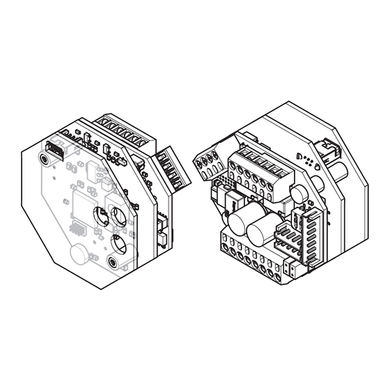
    Informations sur le produit Module IO OneSystem uP Le module IO OneSystem uP (Fig. 1) est un module IO qui permet de connecter des produits Hi-O Technology™ (par ex. les serrures OneSystem avec des composants électroniques conventionnels) sur des systèmes de porte (par ex. des installations de contrôle d’accès et des systèmes de détection d’incendie).
  • Page 53: Le Bus Hi-O Technology

    Le bus Hi-O Technology™ Le bus Hi-O Technology™ (Highly Intelligent Opening) est un bus de réseau CAN pour la connexion de composants électroniques (appareils) sur des systèmes de porte (notice d’instructions séparée D00873 Câblage OneSystem Hi-O Technology™). Il sert à commander respectivement une porte. La surveillance de l’état et l’échange d’informations entre les différents appareils s’effectuent via le bus CAN.
  • Page 54 Fig. 2  : Composants sur les platines État vert jaune rouge En service Hors ligne clignote clignote Informations sur le produit...
  • Page 55: Connexions

    Connexions Connecteur pour les appareils de Commutateur rotatif pour le service réglage des affectations des sorties Bornes de connexion pour Hi-O 2 sorties sans potentiel Technology Commutateurs DIP 1 et 2 SYSCON7 pour sorties Open Collector Connecteur SYSCON4 pour Hi-O Cavaliers 1 et 2 Technology Quatre entrées numériques et...
  • Page 56: Consignes

    Consignes À propos de cette notice Cette notice d’instructions a été rédigée à l’attention des électrotechniciens et du personnel formé. Lisez ces instructions afin d’installer et d’utiliser l’appareil en toute sécurité et de pouvoir exploiter toutes les possibilités de mise en œuvre proposées.
  • Page 57: Consignes De Sécurité

    Consignes de sécurité Attention ! Un câblage non protégé peut être manipulé : Les composants de porte électro- niques peuvent être reliés entre eux et commandés via le câblage. Le câblage doit être réalisé de façon à être protégé des manipulations et des pannes et doit être inaccessible de l’extérieur.
  • Page 58: Définitions

    Définition Désignation Description Terminer/ Un bus Hi-O Technology™ doit être équipé d'une résistance terminale qui le Terminaison termine. En l'absence de résistance terminale, la transmission de données peut être perturbée. Bus Hi-O Le bus Hi-O Technology™ (Highly Intelligent Opening) est un bus CAN pour le Technology™...
  • Page 59: Utilisation Conforme À L'usage Prévu

    Utilisation conforme à l’usage prévu ® Le module IO N5951 OneSystem (module IO) convient pour la connexion numérique de serrures OneSystem ® via Hi-O Technology™. Dans ce contexte, il sert de moyen de connexion à des appareils conventionnels, comme par exem- ple : ·...
  • Page 60: Installation

    Installation Connexions Bornes Hi-O Description CAN H fil blanc CAN L fil brun VB + fil vert VB – fil jaune Entrées Description In 1 Les entrées numériques GND (terre) (5 – 10) doivent uniquement être commandées par des In 2 contacts sans potentiel In 3 (bouton de validation/...
  • Page 61 Commutateur DIP Position Effet Résistance terminale Pas de résistance terminale Groupe Hi-O 1 Groupe Hi-O 0 SYSCON4 Description VB + CAN H CAN L VB – SYSCON7 Description Sortie 3 Noir Open-Collector Rouge 7 Ausgang 3 Sortie 5 Gris Open-Collector 6 Vcc 5 Ausgang 5 4 Ausgang 6...
  • Page 62: Raccordement Du Système De Détection D'incendie

    Raccordement du système de détection d’incendie Cavalier 1 et cavalier 2 Description Pas d'alarme d'incendie Cavalier installé Raccordement local Cavalier non positionné Raccordement central Cavalier non positionné Installation...
  • Page 63: Montage

    le montage. Préparation du montage Veillez à ce que les points suivants soient assurés avant le montage : Prérequis · La planification est terminée. · La fonction de groupes Hi-O et les sorties requises sont définies et les positions des commutateurs DIP sont réglées correctement. ·...
  • Page 64: Entrées Et Sorties

    Entrées et sorties Commutateur rotatif - Configuration des entrées et sorties Position Fonction Entrées Commande de béquille / Monitoring Validation externe Commande de béquille cylindre Validation externe Commande de béquille contr. d’accès / cylindre Validation externe Serrure motorisée contr. d’accès Validation externe Serrure motorisée contr.
  • Page 65 BMA (détecteur d' i ncendie) Contact de porte externe Verrouillage central Contact de porte externe Verrouillage central Contact de porte externe Verrouillage central Contact de porte externe Verrouillage central Détecteur d’incendie Contact de porte externe Verrouillage central Détecteur d’incendie Contact de porte externe Verrouillage central Détecteur d’incendie Contact de porte externe...
  • Page 66: Entrées

    Entrées Input « IN1 » – Validation externe Un bouton de déverrouillage (ou un autre contact de commande sans potentiel) peut être raccordé à cette entrée. Selon les appareils Hi-O Technology™ rac- cordés, le contact de commande active différents processus : · une serrure motorisée rentre le(s) pêne(s) dormant(s), ·...
  • Page 67 Input « IN3 » – Verrouillage central Le contact de commande d’un verrouillage central peut être raccordé à cette entrée. Selon les appareils Hi-O Technology™ raccordés, le contact de commande active différents processus : · une serrure motorisée déverrouillée verrouille dès que la porte est fermée, ·...
  • Page 68: Sorties

    Sorties Béquille extérieure actionnée Pour une serrure avec fouillot en deux parties : la sortie commute lorsque la béquille extérieure est actionnée. Béquille intérieure actionnée Pour une serrure avec fouillot en deux parties : la sortie commute lorsque la béquille intérieure est actionnée. Pour une serrure avec fouillot en une seule pièce : la sortie commute lorsqu’une béquille est actionnée.
  • Page 69: Caractéristiques Techniques

    Caractéristiques techniques Caractéristique Valeur Indice de protection IP 30 (si intégralement monté) Lieu d'exploitation Zone intérieure Tension d’alimentation conformément à DIN EN 60950-1 TBTS 12 V (–10%) à 24V (+10%) DC optimale 24 VDC Courant absorbé max. à 24 VDC 70 mA, 1,9 W Courant absorbé...
  • Page 70: Problème, Cause, Solution

    Problème, cause, solution Pas de réaction au signal de commande Problème Cause possible Solution La serrure ne La serrure est rac- Si vous utilisez le bus Hi-O déverrouille pas, cordée simultanément Technology™ avec le module IO, bien que l'entrée via le bus Hi-O déconnectez le câble de raccorde- de commande Technology™.
  • Page 71: Accessoires, Entretien, Garantie, Élimination

    Accessoires, entretien, garantie, élimination Accessoires Désignation Description N° de commande Bloc d’alimentation Alimentation électrique 1 0 0 3 – 2 4 – 4 – – – – 1 0 1003-24-4 24 V / 4 A courant permanent pour serrure mo- Tension de sortie stabilisée torisée pour le montage dans une...
  • Page 72: Garantie

    Garantie La durée de garantie légale et les conditions générales de vente et de livraison de la société ASSA ABLOY Sicherheitstechnik GmbH (www.assaabloy.de) s’appliquent. Élimination Éliminer les composants selon les instructions relatives au système EPD (Environ- mental Product Declaration). Les matériaux d’emballage doivent être apportés à un service de collecte et de valorisation des déchets.
  • Page 73 Accessoires, entretien, garantie, élimination...
  • Page 74 La presente documentazione è protetta in tutte le sue parti dal diritto d'autore. Qualsiasi utilizzazione e/o modifica non strettamente contemplata dalla legge in tema di protezione del diritto d'autore senza previa autorizzazione di ASSA ABLOY Sicherheitstechnik GmbH costituisce un illecito ed è punibile secondo la legge.
  • Page 75 Indice Informazioni sul prodotto ......76 Modulo IO OneSystem da incasso ......... . . 76 Bus Hi-O Technology™...
  • Page 76: Informazioni Sul Prodotto

    Informazioni sul prodotto Modulo IO OneSystem da incasso Il modulo IO OneSystem da incasso (Fig. 1) è un modulo IO che serve a collegare prodotti Hi-O-Technology (ad esempio serrature OneSystem, a componenti elettronici tradizionali) in sistemi di porte (ad es. impianti di controllo accessi e allarmi antincendio).
  • Page 77: Bus Hi-O Technology

    Bus Hi-O Technology™ Il bus Hi-O Technology™ (Highly Intelligent Opening) è un bus di rete CAN che serve a collegare i componenti elettronici (dispositivi) in sistemi di porte (istruzioni separate D00873 OneSystem Hi-O Technology™ - Cablaggio). Serve a controllare una porta alla volta. Il monitoraggio dello stato e lo scambio di informazioni tra i singoli dispositivi avvengono tramite il bus CAN.
  • Page 78 Fig. 2 : Componenti sulle schede Stato verde giallo rosso Funzionamento Offline lampeggia lampeggia Informazioni sul prodotto...
  • Page 79: Connessioni

    Connessioni Connettore per dispositivi di Selettore per l'assegnazione delle servizio uscite Hi-O Technology Connessione 2 uscite a potenziale zero Microinterruttori 1 e 2 SYSCON7 per uscite open collector Hi-O Technology Connessione Jumper 1 e 2 SYSCON4 4 uscite digitali e collegamento per allarme antincendio Attenzione! Pericolo di danneggiamento, qualora l’azionamento delle entrate avvenga tra-...
  • Page 80: Indicazioni

    Indicazioni Riguardo alle presenti istruzioni Le presenti istruzioni sono rivolte a elettrotecnici e a personale adeguatamente addestrato. Leggere le presenti istruzioni per l’uso per montare e utilizzare il dispositivo in modo sicuro e per informazioni sulle applicazioni consentite. Istruzioni correlate ·...
  • Page 81: Indicazioni Di Sicurezza

    Indicazioni di sicurezza Attenzione! Un cablaggio non protetto può essere manomesso: Con il cablaggio vengono collegati tra loro e controllati componenti elettronici di porte. Il cablaggio deve essere realizzato in modo tale da essere protetto da manomissioni e anomalie e non deve essere accessibile dall’esterno.
  • Page 82: Terminologia

    Terminologia Descrizione Descrizione Terminazione Un bus Hi-O Technology™ deve essere provvisto di resistenza terminale che programma il bus. Se la resistenza terminale è assente, la trasmissione di dati può risultare disturbata. Il bus Hi-O Technology™ (Highly Intelligent Opening) è un bus CAN che serve Hi-O Technology™...
  • Page 83: Uso Conforme Alle Disposizioni

    Uso conforme alle disposizioni ® Il modulo IO N5951 OneSystem   (modulo IO) è indicato per il collegamento digi- tale di serrature OneSystem ® mediante Hi-O Technology™. Serve come collega- mento a dispositivi comuni, ad es.: · controllo accessi, · controlli di interblocco sul posto oppure ·...
  • Page 84: Installazione

    Installazione Connessioni Connessioni Hi-O Descrizione CAN H filo bianco CAN L filo marrone VB + filo verde VB – filo giallo Ingressi Descrizione In 1 Gli ingressi digitali (5 – 10) pos- sono essere attivati esclusiva- In 2 mente da contatti a potenzi- In 3 ale zero (pulsante di sblocco, contatto di relè).
  • Page 85 Microinterruttore Effetto sizione Resistenza terminale Nessuna resistenza terminale Gruppo Hi-O 1 Gruppo Hi-O 0 SYSCON4 Descrizione VB + CAN H CAN L VB – SYSCON7 Descrizione Uscita 3 Nero Open collector Rosso 7 Ausgang 3 Uscita Grigio Open collector 6 Vcc 5 Ausgang 5 4 Ausgang 6 Uscita 6...
  • Page 86: Collegamento Dell'allarme Antincendio

    Collegamento dell‘allarme antincendio Jumper 1 e jumper 2 Descrizione nessun allarme antincendio Jumper installato connessione locale Jumper non installato connessione centralizzata Jumper non installato Installazione...
  • Page 87: Montaggio

    Montaggio Operazioni preliminari al montaggio Prima del montaggio, accertarsi di quanto segue: Requisiti · La progettazione è conclusa. · La funzione del gruppo Hi-O e i terminali necessari sono stabiliti e le posizioni dei microinterruttori sono impostate correttamente. · Il ponticello sui pin (jumper) è installato correttamente. ·...
  • Page 88: Ingressi E Uscite

    Ingressi e uscite Selettore - Assegnazione degli ingressi e delle uscite Posizione Funzione Ingressi Comando a maniglia / monitoraggio Abilitazione esterna Azionamento a maniglia cilindro Abilitazione esterna Azionamento a maniglia Zuko / cilindro Abilitazione esterna Serratura motorizzata Zuko Abilitazione esterna Serratura motorizzata Zuko / cilindro Abilitazione esterna Serratura motorizzata cilindro / BMA...
  • Page 89 Contatto porta esterno Bloccaggio centralizzato --- Contatto porta esterno Bloccaggio centralizzato --- Contatto porta esterno Bloccaggio centralizzato --- Contatto porta esterno Bloccaggio centralizzato Allarme antincendio Contatto porta esterno Bloccaggio centralizzato Allarme antincendio Contatto porta esterno Bloccaggio centralizzato Allarme antincendio Contatto porta esterno Bloccaggio centralizzato --- Maniglia esterna azionata Maniglia accoppiata Porta chiusa...
  • Page 90: Ingressi

    Ingressi Input “IN1” – Abilitazione esterna All’ingresso è possibile collegare un pulsante di sblocco (o un altro contatto di co- mando a potenziale zero). A seconda dei dispositivi Hi-O Technology™ collegati, il contatto di comando attiva processi diversi: · una serratura motorizzata fa retrarre il chiavistello / i chiavistelli, ·...
  • Page 91 Input “IN3” – Bloccaggio centralizzato All’ingresso è possibile collegare il contatto di comando di una chiusura centrale. A seconda dei dispositivi Hi-O Technology™ collegati, il contatto di comando attiva processi diversi: · una serratura motorizzata sbloccata si blocca non appena la porta è chiusa, ·...
  • Page 92: Uscite

    Uscite Maniglia esterna azionata In caso di serratura con doppio nottolino maniglia: L’uscita scatta quando viene azionata la maniglia esterna. Maniglia interna azionata In caso di serratura con nottolino maniglia diviso: L’uscita scatta quando viene azionata la maniglia interna. In caso di serratura con nottolino maniglia non diviso: L’uscita scatta quando viene azionata la maniglia.
  • Page 93: Dati Tecnici

    Dati tecnici Caratteristiche Spiegazione/Dimensioni Tipo di protezione IP 30 (se completamente montata) Luogo di applicazione Per interni Tensione di alimentazione Secondo DIN EN 60950-1 SELV Da 12 V (– 10%) a 24 V (+ 10%) c.c. ottimale 12 V c.c. Consumo di corrente massimo a 24 V c.c.
  • Page 94: Problema, Causa, Soluzione

    Problema, Causa, Soluzione Nessuna reazione al segnale di comando Problema Possibile causa Soluzione La serratura non si La serratura è collegata In caso di funzionamento sblocca nonostan- contemporaneamente mediante il Bus Hi-O Technology™ te l'attivazione tramite il Bus Hi-O con il modulo IO, scollegare il dell'ingresso di Technology™.
  • Page 95: Accessori, Manutenzione, Garanzia, Smaltimento

    Accessori, manutenzione, garanzia, smaltimento Accessori Descrizione Descrizione Codice ordinativo Alimentatore Alimentazione di corrente 1 0 0 3 – 2 4 – 4 – – – – 1 0 1003-24-4 Corrente continua 24 V / 4 A per serratura motor- Tensione in uscita izzata stabilizzata Per il montaggio in quadri di...
  • Page 96: Garanzia Commerciale

    Garanzia commerciale Si applicano i termini di garanzia legali e le condizioni di vendita e consegna di ASSA ABLOY Sicherheitstechnik GmbH (www.assaabloy.de). Smaltimento Smaltimento secondo EPD (Environmental Product Declaration). I materiali dell’imballaggio devono essere conferiti all’impianto di riciclo. Il prodotto deve essere smaltito come rifiuto elettronico.
  • Page 98 Hi-O Technology™ is een geregistreerd handelsmerk van de ASSA ABLOY-groep. Open source-licenties ASSA ABLOY Sicherheitstechnik GmbH levert de broncode van de in het kader van open source-licenties gebruikte software(bijvoorbeeld FreeRTOS™, newlib, lwIP) op aanvraag: http://www.assaabloy.com/com/global/opensourcelicense/...
  • Page 99 Inhoudsopgave Productinformatie ........100 OneSystem IO-module uP ..........100 De Hi-O Technology™-bus.
  • Page 100: Productinformatie

    Productinformatie OneSystem IO-module uP De OneSystem IO-module uP (Afb. 1) is een IO-module voor aansluiting van Hi-O Technology-producten (bijvoorbeeld de OneSystem veiligheidssloten met conventionele elektronische componenten) in deursystemen (bijvoorbeeld toegangscontrolesystemen en brandmeldingssystemen). De OneSystem IO-module uP is geschikt voor inbouw in een inbouwdoos. Afb. 1 : productweergave De OneSystem IO-module uP biedt: ·...
  • Page 101: De Hi-O Technology™-Bus

    De Hi-O Technology™-bus De Hi-O Technology™-bus (Highly intelligent Opening) is een CAN-netwerkbus voor het aansluiten van elektronische componenten (apparaten) in deursyste- men (afzonderlijke handleiding D00873 OneSystem Hi-O Technology™-bekabeling). Het dient voor de elektrische besturing van telkens één deur. De toestandsbewak- ing en de informatie-uitwisseling tussen de individuele apparaten vinden plaats www.assaabloy.de via de CAN-bus.
  • Page 102 Afb. 2 : componenten op de printplaten Status bedrijf offline knippert knippert Productinformatie...
  • Page 103: Aansluitingen

    Aansluitingen Aansluitbus voor Draaischakelaar voor het instellen serviceapparaten van de uitgangen Hi-O Technology -aansluiting 2 potentiaalvrije uitgangen DIP-switch 1 en 2 SYSCON7 voor open collector-uitgangen Hi-O Technology Jumper 1 en 2 SYSCON4-aansluiting vier digitale ingangen en een aansluiting voor een brandmeldingssysteem Let op! Gevaar voor beschadiging bij potentiaalgebonden aansturing van ingangen:...
  • Page 104: Opmerkingen

    Opmerkingen Over deze handleiding Deze handleiding is geschreven voor elektrotechnici en bevoegd geschoold personeel. Lees deze handleiding aandachtig, om het product veilig te kunnen installeren en gebruiken en de toegestane gebruiksmogelijkheden die het biedt, volledig te benutten. bijbehorende handleidingen · D00873XX OneSystem Hi-O-bekabeling Betekenis van de symbolen Gevaar! Veiligheidsadvies: Het niet in acht nemen heeft ernstig of dodelijk letsel tot...
  • Page 105: Veiligheidsaanwijzingen

    Veiligheidsaanwijzingen Let op! Onbeschermde bedrading kan gemanipuleerd worden: Via de bedrading worden de elektronische deurcomponenten met elkaar verbonden en aang- estuurd. De bedrading moet ter bescherming tegen manipulaties en storingen beschermd worden geïnstalleerd en mag niet van buitenaf toegankelijk zijn. Materiële schade door aansluiting op USB-apparaten: De aansluitbus op het behuizingsdeksel (Afb.
  • Page 106: Begripsomschrijving

    Begripsomschrijving Aanduiding Beschrijving Afsluiten Een Hi-O Technology™-bus moet van een afsluitweerstand worden voorzien die de bus afsluit. Ontbreekt de afsluitweerstand, dan kan de datatransmissie verstoord zijn. Hi-O Technolo- De Hi-O Technology™-bus (Highly Intelligent Opening) is een CAN-bus om gy™-bus verbindingen tot stand te brengen met elektronische componenten (ap- paraten) in deursystemen.
  • Page 107: Beoogd Gebruik

    Beoogd gebruik ® De OneSystem IO-module N5951 (IO-module) is geschikt voor digitale aansluiting van OneSystem ® -sloten via Hi-O Technology™. Zij dient daarbij als verbind- ingselement met conventionele apparaten, zoals bijv.: · toegangscontrole, · sluisbesturingen op de desbetreffende locatie of ·...
  • Page 108: Installatie

    Installatie Aansluitingen Hi-O-aansluitingen Beschrijving CAN H witte ader CAN L bruine ader VB + groene ader VB – gele ader Ingangen Beschrijving In 1 De digitale ingangen (5 – 10) mogen uitsluitend door poten- In 2 tiaalvrije contacten (inschakel- In 3 knop, relaiscontact) worden aangestuurd.
  • Page 109 DIP-switch Positie Effect Afsluitweerstand geen afsluitweerstand Hi-O-groep 1 Hi-O-groep 0 SYSCON4 Beschrijving VB + CAN H CAN L VB – SYSCON7 Beschrijving Uitgang 3 Zwart Open collector Rood 7 Ausgang 3 Uitgang 5 Grijs Open collector 6 Vcc 5 Ausgang 5 4 Ausgang 6 Uitgang 6 Bruin...
  • Page 110: Aansluiting Van Het Brandmeldingssysteem

    Aansluiting van het brandmeldingssysteem Jumper 1 en jumper 2 Beschrijving geen brandalarm Jumper geplaatst lokale aansluiting Jumper niet geplaatst centrale aansluiting Jumper niet geplaatst Installatie...
  • Page 111: Montage

    Montage Montagevoorbereiding Zorg vóór de montage voor de volgende punten: Voorwaarden · De planning is voltooid. · De Hi-O-groepsfunctie en de vereiste afsluitingen zijn vastgelegd en de DIP-switch-posities zijn correct ingesteld. · De brug op de pins (jumper) is correct geplaatst. ·...
  • Page 112: Ingangen En Uitgangen

    Ingangen en uitgangen Draaischakelaar - configuratie van de in- en uitgangen Positie Functie Ingangen Krukbesturing / monitoring Externe vrijgave Extern deurcontact Krukbesturing cilinder Externe vrijgave Extern deurcontact Krukbesturing Zuko / cilinder Externe vrijgave Extern deurcontact Motorslot Zuko Externe vrijgave Extern deurcontact Motorslot Zuko / cilinder Externe vrijgave Extern deurcontact...
  • Page 113 Centrale vergrendeling Centrale vergrendeling Centrale vergrendeling Centrale vergrendeling Brandmelding Centrale vergrendeling Brandmelding Centrale vergrendeling Brandmelding Centrale vergrendeling Buitendeurkruk Deurkruk gekoppeld Deur gesloten cilinder bediend Buitendeurkruk Deurkruk gekoppeld Deur gesloten Binnendeurkruk bediend bediend Buitendeurkruk Deurkruk gekoppeld Deur gesloten Binnendeurkruk bediend bediend Aansturing Ontgrendeld Deur gesloten...
  • Page 114: Ingangen

    Ingangen Input “IN1” – Externe vrijgave Op de ingang kan een vrijgavetoets (of een ander potentiaalvrij aansturingscon- tact) worden aangesloten. Afhankelijk van de aangesloten Hi-O Technology™-ap- paraten activeert het aansturingscontact verschillende processen: · een motorslot trekt de grendel / de grendels in, ·...
  • Page 115 Input “IN3” – Centrale vergrendeling Het aansturingscontact van een centrale vergrendeling kan op de ingang worden aangesloten. Afhankelijk van de aangesloten Hi-O Technology™-apparaten activeert het aans- turingscontact verschillende processen: · een ontgrendeld motorslot vergrendelt zodra de deur gesloten is, · een koppelingsslot koppelt de buitendeurkruk, ·...
  • Page 116: Uitgangen

    Uitgangen Buitendeurkruk bediend Bij een slot met gedeelde kruktuimelaar: De uitgang schakelt, wanneer de buiten- deurkruk wordt bediend. Binnendeurkruk bediend Bij een slot met gedeelde kruktuimelaar: De uitgang schakelt wanneer de binnen- deurkruk wordt bediend. Bij een slot met een ongedeelde kruktuimelaar: De uitgang schakelt wanneer een deurkruk wordt bediend.
  • Page 117: Technische Gegevens

    Technische gegevens Eigenschap Vorm Beschermingsklasse IP 30 (indien volledig gemonteerd) Gebruikslocatie Binnenshuis Stroomvoorziening conform DIN EN 60950-1 SELV 12 V (–10%) tot 24V (+10%) DC optimaal 24 VDC max. stroomopname bij 24 VDC 70 mA, 1,9 W max. stroomopname bij 12 VDC 140 mA, 1,5 W Contactbelastbaarheid van de uitgan- 30 V / 1 A...
  • Page 118: Probleem, Oorzaak, Oplossing

    Probleem, oorzaak, oplossing Geen reactie op aansturingssignaal Probleem Mogelijke oorzaak Probleemoplossing Slot ontgrendelt Het slot is tegelijkertijd Maak bij gebruik via de Hi-O niet, hoewel via de Hi-O Technolo- Technology™-bus met de besturingsingang gy™-bus aangesloten. IO-module de grijze aansluitkabel Ontgrendeling van het slot op de functieloze geactiveerd is.
  • Page 119: Toebehoren, Onderhoud , Garantie, Afvalverwijdering

    Toebehoren, onderhoud , garantie, afvalverwijdering Toebehoren Aanduiding Beschrijving Bestelnummer Voeding 1003-24-4 Stroomvoorziening 1 0 0 3 – 2 4 – 4 – – – – 1 0 24 V / 4 A continustroom voor motorslot gestabiliseerde uitgangsspanning Voor de inbouw in verdeelkasten of op DIN-rails Voeding 1003-24-1 Stroomvoorziening...
  • Page 120: Garantie

    Garantie Van toepassing zijn de wettelijke garantietermijnen en de verkoop- en lever- ingsvoorwaarden van ASSA ABLOY veiligheidstechniek GmbH (www.assaabloy.de). Afvalverwijdering Recycling volgens EPD (Environmental Product Declaration). Verpakkingsmaterialen moeten voor recycling worden aangeboden. Het product moet als elektronisch afval worden afgevoerd en verwerkt. De geldende voorschriften betreffende milieubescherming moeten worden nageleefd.
  • Page 121 Toebehoren, onderhoud , garantie, afvalverwijdering...
  • Page 124 ASSA ABLOY is the global ASSA ABLOY is the global leader in door opening solutions, leader in door opening solutions, dedicated to satisfying dedicated to satisfying end-user needs for security, end-user needs for security, safety and convenience safety and convenience...

Ce manuel est également adapté pour:

N5951

Table des Matières