Table des Matières
Publicité
Les langues disponibles
Les langues disponibles
Publicité
Chapitres
Table des Matières

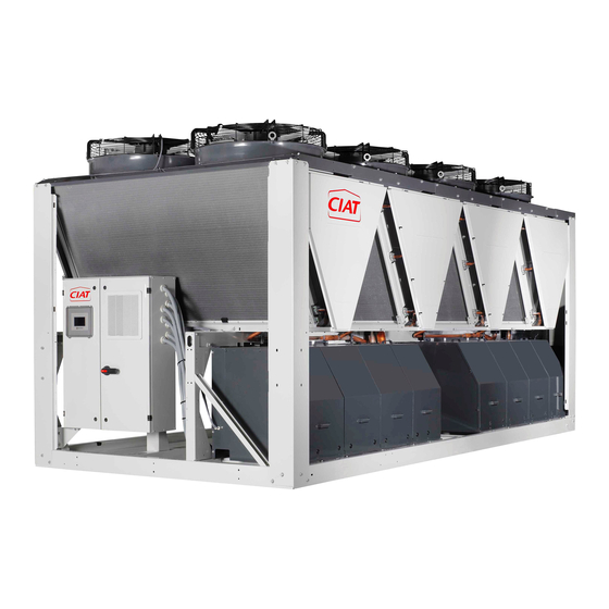
Sommaire des Matières pour CIAT Aquaciat 2 LD Série
- Page 1 N 05.30 F 03 - 2008...
-
Page 2: Table Des Matières
SOMMAIRE PAGE Introduction Réception de l’appareil Garantie Consignes de sécurité Emplacement du groupe Manutention et mise en place Implantation Isolateurs de vibrations Fixation au sol Limites évaporateur Plage d’utilisation Protection antigel eau glycolée Raccordement hydraulique Diamètre des connexions d’eau Raccordements électriques Principaux composants du circuit frigorifique Régulation et appareils de sécurité... -
Page 3: Introduction
Introduction - Circuits frigorifiques sous pression - Présence de fluide frigorigène Les groupes de production d'eau glacée AQUACIAT 2 froid seul série LD, LDC, LDH et réversible série ILD, ILDC, ILDH - Présence de tension électrique permettent de répondre aux besoins en climatisation et en Seul un personnel expérimenté... -
Page 4: Manutention Et Mise En Place
Manutention et mise en place - Utiliser des élingues d'une capacité adaptée et suivre les instructions de levage figurant sur les plans livrés avec le Pour lever l'appareil, fixer les élingues aux trous de groupe. manutentions, prévus à cet effet. - Attention, le centre de gravité... -
Page 5: Implantation
Implantation (Dégagements à respecter) Il est important d'installer les groupes avec suffisamment d'espace libre : ■ Pour éviter la recirculation de l'air de refoulement du condenseur par réaspiration. ■ Pour la maintenance du groupe. 350V à 700V 80V à 300V 702V à... - Page 6 Isolateurs de vibrations (Fourniture standard) Pour des applications à très basses vibrations, il est nécessaire d'installer sous le groupe les plots antivibratiles. Le positionnement des plots doit être conforme aux emplacements prévus ci-dessous. LDH - ILDH Tailles 1156 50x120 50x200 50x200 1076 50x200 2676...
-
Page 7: Fixation Au Sol
702 à 1100 3684 2125 La fixation au sol du châssis est possible (plots avec boulons hors fournitures CIAT) dureté à définir en fonction du poids et du centre de gravité de l’appareil. Limites évaporateur Les courbes ci-dessous représentent les écarts de température minimum et maximum admissibles sur l’eau glacée ou glycolée en fonction de la température de sortie. -
Page 8: Plage D'utilisation
Plage d'utilisation (à pleine puissance) LD - LDC - LDH 80V à 1100V AUTOADAPTATIF OVERBOOST Option XtraFan 80V à 700V Glycol obligatoire +15 +18 -> Sortie évaporateur °C ILD - ILDC - ILDH 80V à 1100V Fonctionnement en mode FROID OVERBOOST AUTOADAPTATIF Option XtraFan... -
Page 9: Protection Antigel Eau Glycolée
Protection antigel eau glycolée Le tableau et les courbes ci-dessous indiquent les pourcentages de glycol minimum à prévoir dans l'installation en fonction du point de congélation. ATTENTION : la concentration en glycol doit protéger le fluide au moins 5 °C en dessous de la température de sortie d'eau prévue à... -
Page 10: Diamètre Des Connexions D'eau
être d’origine atmosphérique. Suivant la situation géographique du site et le type de réseau (enterré ou aérien) un parafoudre peut être exigé par la réglementation locale. La garantie CIAT ne saurait s’appliquer en cas de non-respect des normes en vigueur dans le pays (NF C 15100 en France) -
Page 11: Principaux Composants Du Circuit Frigorifique
Principaux composants Régulation et appareils de sécurité du circuit frigorifique Module électronique de régulation et de signalisation Compresseurs Tous les groupes de la gamme AQUACIAT sont équipés d'un Les appareils LD-LDC-LDH-ILD-ILDC-ILDH utilisent des module électronique de régulation et de signalisation à compresseurs Scroll hermétiques. -
Page 12: Gestion Des Sécurités
Gestion des sécurités le défaut est signalé par une LED sur le pupitre du régulateur. ● Capteur BP Toutes les sécurités du groupe sont gérées par la carte Grâce au capteur BP et à la sonde de sortie d’eau échangeur, électronique du régulateur. -
Page 13: Emplacement Des Thermistances De Sécurité
Emplacement des thermistances de sécurité LD - LDC - LDH 80 à 300 Mod. 80 à 150 (Sauf ILDH Mod. 180 à 300 Option désurchauffeur Mod. 180 à 300 uniqu. Echangeur à plaques Diffuseur LD - LDC - LDH 350 à 700 Circuit 2 Circuit 2 : Option désurchauffeur... - Page 14 LD - LDC - LDH 702 à 1100 Uniquement sur les modèles 1000 et 1100 Circuit 2 Option désurchauffeurs Sonde ambiance échangeur Monter la rondelle de restriction gaz à Circuit 1 l’aspiration des compresseurs 2 et 4 Uniquement sur les modèles 1000 et 1100 Option désurchauffeurs Batterie 1...
- Page 15 ILD - ILDC - ILDH 350 à 700 CIRCUIT 1 CIRCUIT 2 Raccordement en eau option désurchauffeurs modèles 500 à 700 Option désurchauffeur Dans le cas Modèle 500 Circuit 2 Voyant huile tandem A partir Comp ZPI80 Option Pression désurchauffeur différentielle Avant brasage : ajout rondelle de restriction...
-
Page 16: Réglage Des Appareils De Régulation Et De Sécurité
Réglage des appareils de régulation et de sécurité Organes de régulation Fonction Symbole électrique Réglage et de sécurité Circuit 1 Circuit 2 Sonde air extérieur Sonde entrée eau échangeur Sonde sortie eau échangeur B10-B11 Sonde de batterie (ILD-ILDC- Régulation + sécurité ILDH) Sonde de refoulement Régulateur... - Page 17 Mise en route Respecter la procédure ci-dessous : - Ouvrir totalement la vanne de réglage - Le démarrage et la mise en route doivent être effectués par - Laisser fonctionner la pompe pendant 2 heures afin d'éliminer un technicien qualifié. d'éventuelles particules solides présentes dans le circuit - Le démarrage et les essais de fonctionnement doivent être - Lire la perte de charge de l'échangeur à...
-
Page 18: Données Techniques - Froid Seul
Données techniques - Froid seul LD - LDC - LDH 100V 120V 150V 180V 200V 240V 300V Puissance frigorifique ① 19.7 22.4 26.3 29.9 38.9 46.7 53.1 61.0 76.8 Puissance absorbée 6.80 7.86 8.80 10.4 13.4 14.5 17.7 20.1 27.1 Efficacité... - Page 19 Données techniques - Froid seul LD - LDC - LDH 350V 400V 500V 540V 600V 700V 702V 800V 900V 1000V 1100V Puissance frigorifique ① 92.5 102.6 123.9 135.9 151.1 173.3 189.3 209.9 250.9 270.6 291.5 Puissance absorbée 30.4 35.4 45.2 47.6 54.6 61.33...
-
Page 20: Données Techniques - Pompes À Chaleur Réversible
Données techniques - Pompes à chaleur réversible ILD - ILDC - ILDH 100V 120V 150V 180V 200V 240V 300V Puissance frigorifique ① 20.2 22.9 27.4 30.5 40.5 47.1 53.5 61.9 75.6 Puissance absorbée 10.6 13.0 15.2 18.3 20.7 27.6 Efficacité EER ② 2.93 2.86 3.01... - Page 21 Données techniques - Pompes à chaleur réversible ILD - ILDC - ILDH 350V 400V 500V 540V 600V 700V 702V 800V 900V 1000V 1100V Puissance frigorifique ① 92.8 105.2 128.1 139.9 155.3 163.1 183,4 201,8 239,8 257,9 278,8 Puissance absorbée 31.4 35.2 44.4 46.1...
-
Page 22: Caractéristiques Électriques
Caractéristiques électriques ■ Appareils de base (hors pompe) 100V 120V 150V 180V 200V 240V 300V 350V Alimentation électrique ph/Hz/V 3~50Hz 400V (+6%/-10%) + Terre Tension circuit contrôle ph/Hz/V 1~50Hz 230V (+6%/-10%) -transformateur monté Intensité démarrage hors pompe Intensité démarrage option SOFT START Pouvoir de coupure (régime neutre TN - TT) Section Maxi câbles Intensité... -
Page 23: Relevé De Fonctionnement
Relevé de fonctionnement LD - LDC - LDH - ILD - ILDC - ILDH En Froid Date et Heure Pression d’aspiration Température d’aspiration °C Compresseur Pression de condensation Température de condensation °C Température entrée refoulement °C Température sortie réfrigérant °C Désurchauffeur Température entrée d’eau °C... -
Page 24: Entretien
Entretien coffret électrique. En effet, bien que les compresseurs soient à l'arrêt, la tension demeure sur le circuit de Faire les relevés de fonctionnement et les contrôles suivant puissance tant que le sectionneur du groupe n'est pas tableau ci-dessus au moins 2 fois par an et impérativement, à ouvert. -
Page 25: Analyse Des Anomalies De Fonctionnement
Réfrigérants - généralités Vérifier également le fonctionnement des organes de Ne jamais oublier que les systèmes de réfrigération renferment sécurité. des liquides et des vapeurs sous pression. Contrôles mensuels Toutes les dispositions nécessaires devront être prises lors de Procéder au contrôle de toutes les valeurs figurant dans le l’ouverture partielle du système. - Page 26 Analyse des anomalies de fonctionnement Anomalies Causes probables Instructions Présence d'air dans le circuit d'eau glacée Purger le circuit d'eau glacée Débit d'eau glacée insuffisant - Vérifier l'ouverture des vannes du circuit d'eau glacée - Vérifier le sens de rotation de la pompe, l'absence de cavitation et si la pompe n'est pas sous dimensionnée Pression Débit d'eau glacée suffisant mais température d'eau glacée...
-
Page 27: Raccordement Client Des Fonctions Contrôlées À Distance
Raccordement client des fonctions Commande sélection chaud / froid contrôlées à distance connecteur Alarme du défaut général Raccorder un contact “ C3 ” sur les bornes du connecteur de la connecteur carte CPU (contact libre de toute polarité et de bonne qualité) ●... - Page 28 CONTENTS PAGE Introduction Reception of the unit Guarantee Safety instructions Location of the unit Handling and positioning Positioning Vibration isolators Ground fixing Evaporator limits Operating range Antifreeze protection with glycol solution Hydraulic connection Diameter of the water connections Electrical connections Principal components of the refrigerant circuit Safety regulation and equipment Main functions...
-
Page 29: Introduction
Introduction - Presence of electrical voltage Only experienced, qualified personnel are authorised to handle The AQUACIAT 2 water chillers, whether cooling only series such equipment. LD, LDC, LDH or reversible series ILD, ILDC, ILDH , make it possible to meet the air conditioning and heating requirements It is essential to respect the recommendations and instructions of public and office buildings while also catering for the needs present in this manual and the various diagrams supplied with... -
Page 30: Handling And Positioning
Handling and positioning - Attention, the centre of gravity is not always located in the middle of the unit and the strains applied to the slings are not always identical. To lift the unit, fix the slings to the handling holes provided for this purpose. -
Page 31: Positioning
Positioning (Distances to be respected) It is important to leave adequate free space when installing the units: ■ To prevent the re-intake and recirculation of air discharged from the condenser. ■ For maintenance of the unit. 350V to 700V 80V to 300V 350V à... - Page 32 Vibration isolators (supplied as standard) For very low-vibration applications, it is necessary to install anti-vibration mounts below the unit. The positioning of the mounts must correspond to the locations indicated below. LDH - ILDH Sizes 1156 50x120 50x200 50x200 1076 50x200 2676 Sizes...
-
Page 33: Evaporator Limits
702 to 1100 3684 2125 It is possible to fix the frame to the ground (mounts with bolts not supplied by CIAT), strength to be defined as a function of the unit’s weight and centre of gravity. Evaporator limits The curves below represent the minimum and maximum permitted temperature differences for chilled or glycol solution as a function of the outlet temperature. -
Page 34: Operating Range
Operating range (in full load) ■ LD - LDC - LDH 80V to 1100V ■ LD - LDC - LDH 753Z to 1200Z AUTOADAPTATIVE OVERBOOST Option Xtra Fan 80V to 700V Glycol compulsory +15 +18 -> Evaporator outlet °C ■ ILD - ILDC - ILDH 80V to 1100V COOLING mode operation OVERBOOST AUTOADAPTATIVE... -
Page 35: Antifreeze Protection With Glycol Solution
Antifreeze protection with glycol solution The table and the curves below indicate the minimum percentages to be provided in the installation as a function of the freezing point. ATTENTION: the glycol concentration must protect the fluid to at least 5°C below the water outlet temperature expected at the evaporator in order to permit the correct regulation of the evaporator minimum pressure regulator. -
Page 36: Diameter Of The Water Connections
Depending on the geographical location of the site and the type of network (underground or overhead); local regulations may require the presence of a lightning arrestor. The CIAT guarantee shall cease to apply in the event of any failure to comply with applicable standards in the country of... -
Page 37: Principal Components Of The Refrigerant Circuit
Principal components of the Safety regulation and equipment refrigerant circuit Electronic regulation and signalling module Compressors All the units in the AQUACIAT range are equipped with a CONNECT electronic regulation and signalling module based The units LD-LDC-LDH-ILD-ILDC-ILDH use hermetic SCROLL on a microprocessor. -
Page 38: Handling Of Safety Devices
● LP sensor Handling of safety devices The LP sensor and the exchanger water outlet sensor perform All the unit’s safety devices are managed by the regulator’s permanent monitoring to avoid the breakage of the electronics card. If a safety device triggers and shuts down the exchangers. -
Page 39: Location Of Safety Thermistors
Location of safety thermistors LD - LDC - LDH 80 to 300 Mod. 80 to 150 Water Water (Excl. ILDH Mod. 180 to 300 Water Desuperheater option Water Mod. 180 to 300 only Plate heat exchanger Nozzle LD - LDC - LDH 350 to 700 Circuit 2 Circuit 2: Desuperheater option... - Page 40 LD - LDC - LDH 702 to 1100 Models 1000 to 1100 only Circuit 2 Desuperheater option Exchanger Water ambient sensor Mount the gas restriction washer to the Circuit 1 Water suction of compressers 2 and 4 Models 1000 and 1100 only Desuperheater option Water Water...
- Page 41 ILD - ILDC - ILDH 350 to 700 CIRCUIT 1 CIRCUIT 2 Water connection. Desuperheater option. Models 500 to 700 Desuperheater option Water Water Model 500 only Water Water Circuit 2 Water Tandem oil light from comp ZPI80 Differential Desuperheater option pressure Before brazing: add a...
-
Page 42: Adjustment Of Regulation And Safety Equipement
Adjustment of regulation and safety equipement Regulating and Function Electrical symbol Adjustment safety devices Circuit 1 Circuit 2 External air sensor Exchanger water inlet sensor Exchanger water outlet sensor B10-B11 Regulation + safety Coil sensor (ILD-ILDC-ILDH) Outlet sensor CONNECT regulator Exchanger refrigerant inlet sensor Regulation of condensing pressure... - Page 43 Start up Respect the procedure described below: - Fully open the adjusting valve - The unit must be switched on and started up by a qualified engineer. - Allow the pump to run for 2 hours in order to eliminate any solid particles which may be present in the circuit - Start-up and operating tests must be performed with a thermal load and water circulation in the exchangers.
- Page 44 Cooling only - Technical specifications LD - LDC - LDH 100V 120V 150V 180V 200V 240V 300V Cooling capacity ➀ 19.7 22.4 26.3 29.9 38.9 46.7 53.1 61.0 76.8 Power input 6.80 7.86 8.80 10.4 13.4 14.5 17.7 20.1 27.1 EER Efficiency ➁...
- Page 45 Cooling only - Technical specifications LD - LDC - LDH 350V 400V 500V 540V 600V 700V 702V 800V 900V 1000V 1100V Cooling capacity ① 92.5 102.6 123.9 135.9 151.1 173.3 189.3 209.9 250.9 270.6 291.5 Power input 30.4 35.4 45.2 47.6 54.6 61.33...
- Page 46 Reversible unit - Heat pump technical specifications ILD - ILDC - ILDH 100V 120V 150V 180V 200V 240V 300V Cooling capacity ➀ 20.2 22.9 27.4 30.5 40.5 47.1 53.5 61.9 75.6 Power input 10.6 13.0 15.2 18.3 20.7 27.6 EER Efficiency ➁ 2.93 2.86 3.01...
- Page 47 Reversible unit - Heat pump technical specifications ILD - ILDC - ILDH 350V 400V 500V 540V 600V 700V 702V 800V 900V 1000V 1100V Cooling capacity ① 92.8 105.2 128.1 139.9 155.3 163.1 183,4 201,8 239,8 257,9 278,8 Power input 31.4 35.2 44.4 46.1...
-
Page 48: Electrical Specifications
Electrical specifications ■ Standard units (pump not included) 100V 120V 150V 180V 200V 240V 300V 350V Electrical supply ph/Hz/V 3~50Hz 400V (+6%/-10%) + Earth Control circuit voltage ph/Hz/V 1~50Hz 230V (+6%/-10%) - transformer mounted Starting current without pump Starting current SOFT START option Breaking capacity (Neutral condition TN-TT) Maxi wires section MAXI rated current ➀... -
Page 49: Operation Statement
Operation statement LD - LDC - LDH - ILD - ILDC - ILDH Cooling Date and Time Suction pressure Suction temperature °C Compressor Condensing pressure Condensing temperature °C Discharge inlet temperature °C Refrigerant outlet temperature °C Desuperheater Water inlet temperature °C Water outlet temperature °C... -
Page 50: Maintenance
Maintenance been opened. Furthermore, there might still be live elements; this is due Complete an operating statement and perform the checks to external slavings connected on the orange colour listed in the table above at least twice a year and, without fail, sectionnable contacts located on the main terminal whenever units which are used on a seasonal basis are Remove the sectionnable part of these contacts before... -
Page 51: Analysis Of Operating Anomalies
Refrigerants - general Monthly inspections Never forget that the refrigerant systems contain pressurised Check all the values specified in the Operation statement table liquids and steam. on the next page. Check for corrosion at all the metal parts (frame, casing, All the necessary precautions must be taken when partially exchangers, electrics boxes etc.). - Page 52 Analysis of operating anomalies Anomalies Probable causes Instructions Presence of air in the chilled water circuit Drain the chilled water circuit Chilled water flow insufficient - Check the opening of the valves in chilled water circuit - Check the direction of rotation of the pump, make sure there is no cavitation and that the pump capacity is sufficient Suction pressure Chilled water flow sufficient but chilled water temperature too...
-
Page 53: Customer Connection Of Remote-Controlled Functions
Customer connection of remote- Heating/cooling selection control controlled functions Connector General fault alarm Connect a C3 contact to the connector terminals on the CPU Connector card (good quality contact with no polarity) ● contact open ➝ COOLING operation ● contact closed ➝ HEATING operation Water pump control alarm Available... - Page 54 INHALT SEITE Einleitung Abnahme des Geräts Garantie Sicherheitsvorschriften Aufstellungsort des Satzes Transport und Aufstellung Aufstellung Schwingungsdämpfer Befestigung am Boden Verdampfer-Grenzwerte Betriebsbereich Glykolwasser-Frostschutz Wasseranschluss Durchmesser der Wasseranschlüsse Elektrische Anschlüsse Hauptbauteile des Kältekreislaufs Regelung und Sicherheitseinrichtungen Hauptfunktionen Steuerung der Sicherheitseinrichtungen Phasenwächter-Bausatz (OPTION) Einbaustelle der Sicherheitsthermistoren Einstellung der Regel- und Sicherheitseinrichtungen Inbetriebnahme...
-
Page 55: Einleitung
Einleitung - Vorhandensein von Kältemittel - Vorhandensein elektrischer Spannung Die Kaltwassersätze AQUACIAT 2 für reinen Kühlbetrieb Serie LD, LDC, LDH und die umschaltbaren Sätze (Heiz- Nur erfahrenes Fachpersonal darf Arbeiten an solchen und Kühlbetrieb) Serie ILD, ILDC, ILDH erfüllen den Ausrüstungen durchführen. -
Page 56: Transport Und Aufstellung
Transport und Aufstellung - Taue mit einer ausreichenden Tragfähigkeit verwenden und die Hebevorschriften der mit dem Satz mitgelieferten Pläne einhalten. Zum Heben des Geräts die Taue an den dafür vorgesehenen Hebe-Ösen anschlagen. - Achtung, der Schwerpunkt ist nicht immer in der Mitte des Geräts, die Lasten sind nicht immer gleichmäßig auf die Seile Sie finden auf dem mit dem Gerät mitgelieferten Raumplan die verteilt. -
Page 57: Aufstellung
Aufstellung (erforderlicher freier Raum) Es ist wichtig, die Sätze mit einem ausreichenden Freiraum aufzustellen: ■ Um die Ausblasluft des Verflüssigers durch Kurzschluss nicht durch erneut anzusaugen. ■ Für die Wartung des Satzes. 350V bis 700V 80V bis 300V 350V à 700V 80V à... - Page 58 Schwingungsdämpfer (Standardlieferumfang) Bei Anwendungen mit sehr niedrigen Schwingungen müssen die Schwingungsdämpfer unter dem Satz angebracht werden. Die Positionierung der Dämpfer muss gemäß den unten angegebenen Einbaustellen erfolgen. LDH - ILDH Größen 1156 50x120 50x200 50x200 1076 50x200 2676 Größen LD - ILD - LDC - ILDC LDH - ILDH 50x700 2122...
-
Page 59: Befestigung Am Boden
3684 2125 GRUNDRAHMEN Die Befestigung des Grundrahmens am Boden ist möglich (Schwingungsdämpfer mit Bolzen nicht im Lieferumfang von CIAT enthalten), Härte in Abhängigkeit von Gewicht und Schwerpunkt des Geräts zu bestimmen. Verdampfer-Grenzwerte Die nachstehenden Kurven zeigen die zulässige Temperaturspreizung zwischen Tiefst- und Höchsttemperatur für Kaltwasser bzw. -
Page 60: Betriebsbereich
Betriebsbereich (bei voller Leistung) LD - LDC - LDH 80V bis 1100V SELBST REGELND OVERBOOST Option XtraFan 80V bis 700V Glykol obligatorisch +15 +18 -> Warmwasseraustrittstemp. in °C ILD - ILDC - ILDH 80V bis 1100V Kühlbetrieb OVERBOOST SELBST REGELND Option XtraFan 80V bis 700V Glykol obligatorisch... -
Page 61: Glykolwasser-Frostschutz
Glykolwasser-Frostschutz Die Tabelle und die Kurven unten geben den minimalen Glykolgehalt in Prozent an, der in der Anlage in Abhängigkeit vom Gefrierpunkt vorzusehen ist. ACHTUNG: Die Glykolkonzentration muss die Flüssigkeit bis mindestens 5 °C unter der am Verdampfer vorgesehenen Wasseraustrittstemperatur schützen, um die korrekte Einstellung des Minimaldruckreglers des Verdampfers zu ermöglichen. -
Page 62: Durchmesser Der Wasseranschlüsse
Sie müssen den Schutz Ihres Geräts gegen Überspannungen aus dem Versorgungsnetz bzw. atmosphärische Überspannungen gewährleisten. Je nach geographischer Lage des Standorts und Netztyp (erdverlegt oder Freileitung) kann ein Blitzableiter von den örtlichen Vorschriften verlangt werden. Die Garantie von CIAT gilt nicht bei Missachtung der in dem Land geltenden Normen (NF C 15100 in Frankreich). -
Page 63: Hauptbauteile Des Kältekreislaufs
Hauptbauteile des Kältekreislaufs Regelung und Sicherheitseinrichtungen Verdichter Geräte LD-LDC-LDH-ILD-ILDC-ILDH benutzen Elektronisches Regel- und Anzeigemodul vollhermetische Scrollverdichter. Alle Sätze der Modellreihe AQUACIAT sind mit einem elektronischen Regel- und Anzeigemodul mit Mikroprozessor Öl Typ CONNECT ausgestattet. Die Verdichter Öl (POE) Copeland 3MAF (32 cSt) für die Das Elektronikmodul steuert den Betrieb der Verdichter. -
Page 64: Steuerung Der Sicherheitseinrichtungen
Steuerung der eingestellten Wert sinkt, wird die Einspeisung des Verdichters (bzw. Verdichter) betroffenen Kältekreislaufs Sicherheitseinrichtungen unterbrochen und die Störung wird durch eine LED auf dem Schaltpult der Regelung angezeigt. Alle Sicherheitseinrichtungen des Satzes werden von der ● ND-Sensor Elektronikkarte Reglers gesteuert. -
Page 65: Einbaustelle Der Sicherheitsthermistoren
Einbaustelle der Sicherheitsthermistoren LD - LDC - LDH 80 bis 300 Mod. 80 bis 150 Wasser Wasser (Außer ILDH) Mod. 180 bis 300 Wasser Option Enthitzer Luft Wasser Nur Mod. 180 bis Plattenwärmeaustauscher Düse LD - LDC - LDH 350 bis 700 Kreislauf 2 Kreislauf Option Enthitzer... - Page 66 LD - LDC - LDH 702 bis 1100 Nur modelles 1000 und 1100 Kreislauf 2 Option Enthitzer Raumfühler Wärmeaustauscher Wasser KM-regulierung am ansaugung des Kreislauf 1 Wasser Verdichters Nur modelle 1000 und 1100 Option Enthitzer Wasser Wasser Wasser Register Register 2 Trockner Modelles 900 bis 1100 Wasser...
- Page 67 ILD - ILDC - ILDH 350 bis 700 KREISLAUF KREISLAUF Wasseranschluss für Wasserboiler (Option), Modelle 500 - 700 Option Enthitzer Wasser Wasser Nür Modelle 500 Wasser Wasser Kreislauf Wasser Ölstandsanzeiger, Ab Element ZPI80 Option Differenzdruck Enthitzer Vor dem Löten: Bei den Modellen 350-400-700 eine Gasdurchfluss- Blende einsetzen...
-
Page 68: Einstellung Der Regel- Und Sicherheitseinrichtungen
Einstellung der Regel- und Sicherheitseinrichtungen Regel- und Sicherheits- Funktion Elektrisches Symbol Regelung einrichtungen Kreislauf 1 Kreislauf 2 Außenluft-Temperaturfühler Wassereintrittsfühler Wärmeaustauscher Wasseraustrittsfühler Wärmeaustauscher B10-B11 Regelung + Sicherheit Register-Temperaturfühler (ILD-ILDC- ILDH) Heißgas-Temperaturfühler Regelung CONNECT Temperaturfühler Kältemittel- eintritt Wärmeaustauscher Regelung von Verflüssigungs- Elektronischer Hochdrucktransmitter BHP1 BHP2 druck + Sicherheit... - Page 69 Inbetriebnahme - Den Druckverlust des Plattenwärmeaustauschers bei der Inbetriebnahme der Pumpe und 2 Stunden danach ablesen - Der Start und die Inbetriebnahme müssen von einem - Wenn der Druckverlust abgenommen hat, bedeutet dies, qualifizierten Techniker durchgeführt werden. dass der Siebfilter verstopft ist; er muss in diesem Fall - Der Start und die Funktionsprüfungen müssen mit einer ausgebaut und gereinigt werden Wärmebelastung...
- Page 70 Technische Kenndaten - Nur KÜHL-Betrieb LD - LDC - LDH 100V 120V 150V 180V 200V 240V 300V Kälteleistung ① 19.7 22.4 26.3 29.9 38.9 46.7 53.1 61.0 76.8 Leistungsaufnahme 6.80 7.86 8.80 10.4 13.4 14.5 17.7 20.1 27.1 EER-Energieeffizienz ② 2.90 2.85 2.99...
- Page 71 Technische Kenndaten - Nur KÜHL-Betrieb LD - LDC - LDH 350V 400V 500V 540V 600V 700V 702V 800V 900V 1000V 1100V Kälteleistung ① 92.5 102.6 123.9 135.9 151.1 173.3 189.3 209.9 250.9 270.6 291.5 Leistungsaufnahme 30.4 35.4 45.2 47.6 54.6 61.33 58.87 68.36...
- Page 72 Technische Kenndaten - Wärmepumpen mit Umkehrbetrieb ILD - ILDC - ILDH 100V 120V 150V 180V 200V 240V 300V Kälteleistung ① 20.2 22.9 27.4 30.5 40.5 47.1 53.5 61.9 75.6 Leistungsaufnahme 10.6 13.0 15.2 18.3 20.7 27.6 EER-Energieeffizienz ② 2.93 2.86 3.01 2.88 3.12...
- Page 73 Technische Kenndaten - Wärmepumpen mit Umkehrbetrieb ILD - ILDC - ILDH 350V 400V 500V 540V 600V 700V 702V 800V 900V 1000V 1100V Kälteleistung ① 92.8 105.2 128.1 139.9 155.3 163.1 183,4 201,8 239,8 257,9 278,8 Leistungsaufnahme 31.4 35.2 44.4 46.1 52.5 59.5 61,5...
-
Page 74: Elektrische Kenndaten
Elektrische Kenndaten ■ Grundgeräte (ohne Pumpe) 100V 120V 150V 180V 200V 240V 300V 350V Elektrischer Anschluss ph/Hz/V 3~50Hz 400V (+6%/-10%) + Erde Steuerkreis ph/Hz/V 1~50Hz 230V (+6%/-10%) - montierter Trafo Anlaufstrom ohne Pumpe Anlaufstrom Option Sanftanlauf Ausschaltvermögen (Nullleiterbetrieb TN - TT) Max. -
Page 75: Betriebsprotokoll
Betriebsprotokoll LD - LDC - LDH - ILD - ILDC - ILDH Kühlbetrieb Datum und Uhrzeit Ansaugdruck Ansaugtemperatur °C Verdichter Verflüssigungsdruck Kondensationstemperatur °C Heißgas-Eintrittstemperatur °C Kältemittel-Austrittstemperatur °C Enthitzer Wasser-Eintrittstemperatur °C Wasser-Austrittstemperatur °C Gas-Eintrittstemperatur °C Flüssigkeits-Austrittstemperatur °C Luftgekühlter Luft-Eintrittstemperatur °C Verflüssiger Außentemperatur °C Luft-Austrittstemperatur... -
Page 76: Wartung
Wartung unterbrechen. Selbst wenn die Verdichter gestoppt sind, liegt solange Spannung am Leistungskreis an, wie der Betriebsprotokolle Prüfungen gemäß Trennschalter des Satzes nicht geöffnet ist. obenstehenden Tabelle mindestens 2 Mal pro Jahr und Außerdem ist es möglich, dass andere Teile immer noch unbedingt bei jeder Inbetriebnahme der saisonbedingt unter Spannung stehen, da externe Steuerungsleitungen betriebenen Sätze durchführen. - Page 77 Kältemittel - Allgemeines Farbwechsel die Qualität prüfen. Niemals vergessen, dass die Kühlsysteme unter Druck Außerdem den Betrieb der Sicherheitseinrichtungen stehende Flüssigkeiten und Dämpfe enthalten. prüfen. Bei einer teilweisen Öffnung des Systems müssen alle Monatliche Prüfungen erforderlichen Sicherheitsmaßnahmen ergriffen werden. Alle Werte in der Betriebsprotokoll-Tabelle der folgenden Seite Das teilweise Öffnen des Primär-Kältkreislaufs führt zum prüfen.
-
Page 78: Analyse Der Funktionsstörungen
Analyse der Funktionsstörungen Störungen Wahrscheinliche Ursachen Anweisungen Vorhandensein von Luft im Kaltwasserkreislauf Den Kaltwasserkreislauf entlüften Kaltwasservolumenstrom unzureichend - Die Öffnung der Ventile des Kaltwasserkreislaufs prüfen - Die Pumpe hinsichtlich Drehrichtung, Kavitation und Unterbemessung prüfen Ansaugdruck Kaltwasservolumenstrom ausreichend aber - Die Wärmebelastung neu berechnen und sicherstellen, dass zu niedrig Kaltwassertemperatur zu niedrig der Satz nicht zu leistungsfähig dafür ist... -
Page 79: Kundenanschluss Der Ferngeschalteten Funktionen
Kundenanschluss der Steuerung Auswahl Heiz- bzw. Kühlbetrieb ferngeschalteten Funktionen Steckverbinder Alarm bei allgemeiner Störung Einen Kontakt “C3” an den Klemmen des Steckverbinders der CPU-Karte Steckverbinder anschließen (potentialfreier Kontakt) l Kontakt offen ® KÜHLBETRIEB l Kontakt geschlossen ® HEIZBETRIEB Steuerung Wasserpumpe Alarm Verfügbar auf Serie LD-LDC-LDH... - Page 80 ÍNDICE PÁGINA Introducción Recepción del aparato Garantía Instrucciones de seguridad Ubicación del grupo Manipulación y colocación Instalación Aisladores de vibraciones Fijación al suelo Límites evaporador Gama de utilización Protección anti-hielo agua glicolada Conexión hidráulica Diámetro de las conexiones de agua Conexiones eléctricas Principales componentes del circuito refrigerante Regulación y aparatos de seguridad...
-
Page 81: Introducción
Introducción - La presencia de fluido refrigerante - La presencia de tensión eléctrica Los grupos de producción de agua fría AQUACIAT 2 sólo frío serie LD, LDC, LDH y reversibles serie ILD, ILDC, ILDH, Sólo puede intervenir en estos equipos personal experto y responden a las necesidades de climatización y calefacción de cualificado. -
Page 82: Manipulación Y Colocación
Manipulación y colocación instrucciones de elevación que figuran en los planos incluidos con el grupo. Para levantar el aparato, fije las eslingas en los agujeros de - Atención: el centro de gravedad no está siempre en medio del manipulación previstos a dicho efecto. aparato y los esfuerzos en las eslingas no son siempre idénticos. -
Page 83: Instalación
Instalación (Espacio libre a respetar) Es importante instalar los grupos con suficiente espacio libre: ■ para evitar la recirculación del aire de descarga del condensador por reaspiración. ■ para el mantenimiento del grupo. 350V a 700V 80V à 300V 350V à 700V 80V a 300V 702V à... - Page 84 Aisladores de vibraciones (estándar) Para aplicaciones con muy pocas vibraciones, es preciso instalar debajo del grupo pies anti-vibraciones. Los pies deben colocarse en los emplazamientos previstos a dicho efecto e indicados a continuación. LDH - ILDH Tamaños 1156 50x120 50x200 50x200 1076 50x200 2676...
-
Page 85: Fijación Al Suelo
702 a 1100 3684 2125 Es posible fijar el chasis al suelo (pies con pernos no suministrados por CIAT). Dureza a definir en función del peso y del centro de gravedad del aparato. Límites del evaporador Las curvas siguientes representan las diferencias de temperatura mínima y máxima admisibles en el agua fría o glicolada en función de la temperatura de salida. -
Page 86: Gama De Utilización
Gama de utilización (a plena potencia) LD - LDC - LDH 80V a 1100V AUTOADAPTATIVO OVERBOOST Option XtraFan 80V a 700V Glicol obligatorio +15 +18 -> Salida evaporador °C ILD - ILDC - ILDH 80V a 1100V Funcionamiento en modo FRIO OVERBOOST AUTOADAPTATIVO Option XtraFan... -
Page 87: Protección Anti-Hielo Agua Glicolada
Protección anti-hielo agua glicolada El cuadro y las curvas siguientes indican los porcentajes de glicol mínimos a prever en la instalación en función del punto de congelación. ATENCIÓN: la concentración de glicol debe proteger el fluido a al menos 5 °C por debajo de la temperatura de salida de agua prevista en el evaporador para permitir un ajuste correcto del regulador de presión mín. -
Page 88: Diámetro De Las Conexiones De Agua
Según la situación geográfica del lugar y del tipo de red (subterránea o aérea), la reglamentación local puede exigir la instalación de un pararrayos. La garantía CIAT no será de aplicación en caso de incumplimiento de las normas en vigor... -
Page 89: Principales Componentes Del Circuito Refrigerante
Principales componentes Regulación y aparatos de seguridad del circuito refrigerante Módulo electrónico de regulación y señalización Compresores Todos los grupos de la gama AQUACIAT disponen de un aparatos LD-LDC-LDH-ILD-ILDC-ILDH utilizan módulo electrónico de regulación y señalización por compresores scroll herméticos. microprocesador CONNECT. -
Page 90: Gestión De Los Dispositivos De Seguridad
Gestión de los dispositivos de ajustado en el regulador, la alimentación del(de los) compresor(es) del circuito refrigerante en cuestión se corta y seguridad el error se indica mediante un LED en la consola del regulador. ● Sensor BP Todos los dispositivos de seguridad del grupo son gestionados por la placa electrónica del regulador. -
Page 91: Ubicación De Las Termistancias De Seguridad
Ubicación de las termistancias de seguridad LD - LDC - LDH 80 a 300 Mod. 80 a 150 Agua Agua (Salvo ILDH Mod. 180 a 300 Agua Opción recuperadores gases calientes Agua Aire Sólo mod. 180 a 300 Intercambiador de placas Difusor LD - LDC - LDH 350 a 700 Circuito 2... - Page 92 LD - LDC - LDH 702 a 1100 Solo modelos 1000 y 1100 Opción recuperadores Circuito 2 gases calientes Sonda Agua ambiente intercambiador Circuito 1 Montar la arandela de restricción en la Agua aspiración de gas de los compresores 2 y 4 Solo modelos 1000 y 1100 Opción recuperadores...
- Page 93 ILD - ILDC - ILDH 350 a 700 CIRCUITO 1 CIRCUITO 2 Conexión de agua.Recuperador de gases calientes opcional.Modelos 500 à 700 Opción recuperadores gases calientes Agua Agua Dans le cas Modèle 500 Agua Agua Circuito Agua Indicador de aceite tándem a partir del comp.ZPI80 Opción recuperadores...
-
Page 94: Puesta En Marcha
Ajuste de los aparatos de regulación y seguridad Dispositivos de regulación Función Símbolo eléctrico Ajuste y seguridad Circuito 1 Circuito 2 Sonda aire exterior Sonda entrada agua intercambiador Sonda salida agua intercambiador B10-B11 Regulación + seguridad Sonda de batería (ILD-ILDC-ILDH) Sonda de descarga Regulador CONNECT... -
Page 95: Ajuste Del Caudal De Agua
Puesta en marcha Respete el procedimiento siguiente: - Abra totalmente la válvula de ajuste. - El arranque y la puesta en marcha deben ser realizados por - Deje funcionar la bomba durante 2 horas para eliminar un técnico cualificado. eventuales partículas sólidas presentes en el circuito. - El arranque y las pruebas de funcionamiento deben ser - Lea la pérdida de carga del intercambiador de placas al poner realizados con una carga térmica y circulación de agua en los... - Page 96 Características tecnicas - Solo frigo LD - LDC - LDH 100V 120V 150V 180V 200V 240V 300V Potencia refrigerante ① 19.7 22.4 26.3 29.9 38.9 46.7 53.1 61.0 76.8 Potencia absorbida 6.80 7.86 8.80 10.4 13.4 14.5 17.7 20.1 27.1 Eficacia EER ②...
- Page 97 Características tecnicas - Solo frigo LD - LDC - LDH 350V 400V 500V 540V 600V 700V 702V 800V 900V 1000V 1100V Potencia refrigerante ① 92.5 102.6 123.9 135.9 151.1 173.3 189.3 209.9 250.9 270.6 291.5 Potencia absorbida 30.4 35.4 45.2 47.6 54.6 61.33...
- Page 98 Características tecnicas - Reversible ILD - ILDC - ILDH 100V 120V 150V 180V 200V 240V 300V Potencia refrigerante ① 20.2 22.9 27.4 30.5 40.5 47.1 53.5 61.9 75.6 Potencia absorbida 10.6 13.0 15.2 18.3 20.7 27.6 Eficacia EER ② 2.93 2.86 3.01 2.88...
- Page 99 Características tecnicas - Reversible ILD - ILDC - ILDH 350V 400V 500V 540V 600V 700V 702V 800V 900V 1000V 1100V Potencia refrigerante ① 92.8 105.2 128.1 139.9 155.3 163.1 183,4 201,8 239,8 257,9 278,8 Potencia absorbida 31.4 35.2 44.4 46.1 52.5 59.5 61,5...
-
Page 100: Características Eléctricas
Características eléctricas ■ Aparatos básicos (sin bomba) 100V 120V 150V 180V 200V 240V 300V 350V Alimentación eléctrica ph/Hz/V 3~50Hz 400V (+6%/-10%) + Tierra Tensión circuito control ph/Hz/V 1~50Hz 230V (+6%/-10%) - transformador montado Intensidad arranque salvo bomba I Intensidad arranque opción SOFT START Poder de corte (régimen neutro TN - TT) Sección máx.cables Intensidad nominal MAX.e ➀... -
Page 101: Informe De Funcionamiento
Informe de funcionamiento LD - LDC - LDH - ILD - ILDC - ILDH En frío Fecha y hora Presión de aspiración Temperatura de aspiración °C Compresor Presión de condensación Temperatura de condensación °C Temperatura entrada descarga °C Temperatura salida refrigerante °C Recuperador gases calientes... -
Page 102: Conservación
Conservación tensión en el circuito de potencia si el seccionador del grupo no está cerrado. Elabore los informes de funcionamiento y realice los controles Además puede haber elementos bajo tensión debido a según el cuadro siguiente al menos 2 veces al año, y elementos externos conectados... -
Page 103: Análisis De Las Anomalías De Funcionamiento
Refrigerantes - generalidades Controles mensuales No olvide nunca que los sistemas de refrigeración contienen Controle todos los valores que figuran en el cuadro Informe de líquidos y vapores a presión. funcionamiento de la página siguiente. Efectúe un control de corrosión del conjunto de las partes Deben tomarse todas las disposiciones oportunas al abrir metálicas (chasis, carrocería, intercambiadores, armarios parcialmente el sistema. - Page 104 Análisis de las anomalías de funcionamiento Anomalías Causas probables Instrucciones Presencia de aire en el circuito de agua fría Purgue el circuito de agua fría Caudal de agua fría insuficiente - Compruebe la abertura de las válvulas del circuito de agua fría - Compruebe el sentido de rotación de la bomba, la ausencia de cavitación y si la bomba no está...
- Page 105 Conexión del cliente de las Control selección caliente / frío funciones controladas a distancia Conector Alarma de avería general Conecte un contacto “ C3 ” a los terminales del conector de la Conector tarjeta CPU (contacto libre de toda polaridad y de buena calidad) ●...
- Page 106 SOMMARIO PAGINA Introduzione Ispezione alla consegna Garanzia Avvisi di sicurezza Posizionamento del gruppo Movimentazione e installazione Luogo di installazione Isolamento delle vibrazioni Fissaggio al suolo Limiti evaporatore Intervalli di utilizzo Protezione antigelo acqua glicolata Collegamento idraulico Diametro dei collegamenti lato acqua Collegamenti elettrici Principali componenti del circuito frigorifero Settaggio e dispositivi di sicurezza...
-
Page 107: Introduzione
Introduzione - Presenza di refrigerante - Presenza di tensione elettrica I refrigeratori d’acqua AQUACIAT 2 solo freddo serie LD, LDC, LDH e reversibili serie ILD, ILDC, ILDH rispondono alle Solo il personale qualificato e con esperienza è autorizzato ad esigenze di climatizzazione e di riscaldamento di edifici per intervenire su questi apparecchi. -
Page 108: Movimentazione E Installazione
Movimentazione e installazione - Non sempre il centro di gravità si trova al centro dell’apparecchio; le sollecitazioni sulle cinghie di sollevamento non sono sempre identiche. Per sollevare l’apparecchio, fissare le cinghie di sollevamento ai fori di ancoraggio previsti. - Sollevare e depositare con cura il gruppo facendo attenzione a non inclinarlo (inclinazione max.: 15°);... -
Page 109: Luogo Di Installazione
Luogo di installazione (Quote di rispetto) Installare il gruppo lasciando uno spazio libero sufficiente: ■ Per evitare il ricircolo dell’aria di mandata del condensatore per riaspirazione. ● Per la manutenzione del gruppo. 350V à 700V 80V à 300V 702V à 1100V 2 apparecchi: A = 2 m 3 apparecchi o più: A = 3 m Per le dimensioni, il peso, il punto di ancoraggio e il centro di gravita, vedere gli schemi forniti con l’apparecchio. - Page 110 Isolamento delle vibrazioni (dotazione standard) Per applicazioni che richiedono vibrazioni molto basse, è necessario installare sotto il gruppo dei supporti antivibranti. L’installazione dei supporti antivibranti deve essere conforme alle posizioni qui indicate. LDH - ILDH Taglie 1156 50x120 50x200 50x200 1076 50x200 2676...
-
Page 111: Fissaggio Al Suolo
702 - 1100 3684 2125 È possibile fissare al suolo il telaio (mediante dei supporti con bulloni non forniti da CIAT); la durezza dei supporti va definita in funzione del peso e del centro di gravità dell’apparecchio. Limiti evaporatore Le curve riportano le variazioni di temperatura, minima e massima, consentite per l’acqua refrigerata o glicolata in funzione della temperatura di uscita. -
Page 112: Intervalli Di Utilizzo
Intervalli di utilizzo (a piena potenza) LD - LDC - LDH 80V - 1100V AUTOADATTATIVO OVERBOOST Opzione XtraFan 80V - 700V Glicole obbligatorio +15 +18 -> Uscita evaporatore °C ILD - ILDC - ILDH 80V - 1100V Funzionamento in modalità FREDDO OVERBOOST AUTOADATTATIVO Opzione XtraFan... -
Page 113: Protezione Antigelo Acqua Glicolata
Protezione antigelo acqua glicolata Le tabelle e le curve riportano le percentuali minime di glicole da prevedere nell’impianto in funzione del punto di congelamento. ATTENZIONE: la concentrazione di glicole dovrà proteggere il liquido ad almeno 5°C al di sotto della temperatura prevista di uscita d’acqua dall’evaporatore al fine di consentire un’impostazione corretta del regolatore di pressione minima dell’evaporatore. -
Page 114: Diametro Dei Collegamenti Lato Acqua
In funzione delle condizioni geografiche del luogo di installazione e del tipo di linea elettrica (interrata o aerea), è possibile che la normativa locale imponga l’adozione di un parafulmine. L’inosservanza delle norme vigenti nel luogo di installazione (normativa NF C 15100 in Francia) invaliderà la garanzia CIAT. -
Page 115: Principali Componenti Del Circuito Frigorifero
Principali componenti Regolazione e dispositivi di sicurezza del circuito frigorifero Modulo elettronico di regolazione e di segnalazione Compressori Tutti i gruppi della gamma AQUACIAT sono dotati di modulo Gli apparecchi LD-LDC-LDH-ILD-ILDC-ILDH utilizzano dei elettronico di regolazione e di segnalazione a microprocessore compressori Scroll ermetici. -
Page 116: Kit Controllore Di Fase (Opzione)
● Sensore BP Gestione dei dispositivi di sicurezza Il sensore BP e la sonda in uscita dell’ acqua dello scambiatore Tutti i dispositivi di sicurezza del gruppo sono gestiti dalla assicurano un controllo costante per evitare di danneggiare gli scheda elettronica del regolatore. Se si attiva un dispositivo di scambiatori. -
Page 117: Ubicazione Dei Termistori Di Sicurezza
Ubicazione dei termistori di sicurezza LD - LDC - LDH 80 - 300 Mod. 80 - 150 Acqua Acqua (Eccetto ILDH) Mod. 180 - 300 Acqua Opzione desurriscaldatore Aria Acqua Mod. 180 - 300 unic. Scambiatore a piastre Diffusore LD - LDC - LDH 350 - 700 Circuito 2 Circuito 2: Opzione desurriscaldatore... - Page 118 LD - LDC - LDH 702 - 1100 Solo sui modelli 1000 e 1100 Circuito 2 Opzione desurriscaldatori Sonda ambiente scambiatore Acqua Circuito 1 Montare la rondella di restrizione gas sul Acqua lato aspirazione dei compressori 2 e 4 Solo sui modelli 1000 e 1100 Opzione desurriscaldatori...
- Page 119 ILD - ILDC - ILDH 350 - 700 CIRCUITO 1 CIRCUITO 2 Collegamento su acqua opzione desurriscaldatori modelli 500 - 700 Opzione desurriscaldatore Acqua Acqua Nel caso Modello 500 Acqua Acqua Circuito 2 Acqua Spia olio tandem Da Comp ZPI80 Aria Opzione Pressione...
-
Page 120: Settaggio Dei Dispositivi Di Regolazione E Di Sicurezza
Settaggio dei dispositivi di regolazione e di sicurezza Dispositivi di regolazione Funzione Simbolo elettrico Regolazione e di sicurezza Circuito 1 Circuito 2 Sonda aria esterna Sonda entrata acqua scambiatore Sonda uscita acqua scambiatore B10-B11 Regolazione + sicurezza Sonda batteria (ILD-ILDC-ILDH) Sonda di mandata Regolatore Sonda entrata fluido... - Page 121 Messa in funzione le eventuali particelle solide presenti nel circuito - Leggere la perdita di carica dello scambiatore a piastre - L’avviamento e la messa in funzione devono essere eseguiti quando si mette in servizio la pompa e dopo 2 ore da un tecnico qualificato.
- Page 122 Caratteristiche tecniche - Solo Freddo LD - LDC - LDH 100V 120V 150V 180V 200V 240V 300V Potenza frigorifera ① 19.7 22.4 26.3 29.9 38.9 46.7 53.1 61.0 76.8 Potenza assorbita 6.80 7.86 8.80 10.4 13.4 14.5 17.7 20.1 27.1 Efficienza EER ②...
- Page 123 Caratteristiche tecniche - Solo Freddo LD - LDC - LDH 350V 400V 500V 540V 600V 700V 702V 800V 900V 1000V 1100V Potenza frigorifera ① 92.5 102.6 123.9 135.9 151.1 173.3 189.3 209.9 250.9 270.6 291.5 Potenza assorbita 30.4 35.4 45.2 47.6 54.6 61.33...
- Page 124 Caratteristiche tecniche - Pompe di calore reversibili ILD - ILDC - ILDH 100V 120V 150V 180V 200V 240V 300V Potenza frigorifera ① 20.2 22.9 27.4 30.5 40.5 47.1 53.5 61.9 75.6 Potenza assorbita 10.6 13.0 15.2 18.3 20.7 27.6 Efficienza EER ② 2.93 2.86 3.01...
- Page 125 Caratteristiche tecniche - Pompe di calore reversibili ILD - ILDC - ILDH 350V 400V 500V 540V 600V 700V 702V 800V 900V 1000V 1100V Potenza frigorifera ① 92.8 105.2 128.1 139.9 155.3 163.1 183,4 201,8 239,8 257,9 278,8 Potenza assorbita 31.4 35.2 44.4 46.1...
-
Page 126: Caratteristiche Tecniche Ed Elettriche
Caratteristiche elettriche ■ Apparecchi di base (senza pompa) 100V 120V 150V 180V 200V 240V 300V 350V Alimentazione elettrica ph/Hz/V 3~50Hz 400V (+6% / -10%) + Terra Tensione circuito di controllo ph/Hz/V 1~50Hz 230V (+6% / -10%) -trasformatore installato Intensità all’avvio, pompa esclusa Intensità... -
Page 127: Rilevamento Dei Valori Di Funzionamento
Rilevamento dei valori di funzionamento LD - LDC - LDH - ILD - ILDC - ILDH Modalità Freddo Data e ora Valvola di aspirazione Temperatura di aspirazione °C Compressore Pressione di condensazione Temperatura di condensazione °C Temperatura entrata mandata °C Temperatura uscita refrigerante °C Desurriscaldatore... -
Page 128: Manutenzione Ordinaria
Manutenzione ordinaria sono fermi, il circuito di potenza rimane alimentato fino a che non viene aperto il sezionatore del gruppo. Verificare i parametri operativi ed eseguire i controlli riportati Inoltre, è possibile che dei componenti rimangano nella precedente tabella almeno 2 volte all’anno e tutte le volte alimentati a causa di asservimenti esterni collegati sui che si mette in servizio un gruppo utilizzato in modo terminali sezionabili di colore arancio sulla morsettiera... -
Page 129: Analisi Delle Anomalie Di Funzionamento
Refrigeranti - generale Controlli mensili Si tenga sempre presente che i sistemi di refrigerazione Controllare tutti i parametri riportati nella tabella Rilevamento contengono liquidi e vapori sotto pressione. dei valori di funzionamento della pagina seguente. Controllare la corrosione di tutte le parti metalliche del gruppo In caso di apertura parziale del sistema, adottare tutte le (telaio, carrozzeria, scambiatori, quadri elettrici...) precauzioni del caso. - Page 130 Analisi delle anomalie di funzionamento Anomalie Cause possibili Istruzioni Presenza d’aria nel circuito acqua refrigerata Sfiatare il circuito dell’acqua refrigerata - Verificare l’apertura delle valvole del circuito d’acqua refrigerata Portata d’acqua refrigerata insufficiente - Controllare il senso di rotazione della pompa, l’assenza di cavitazione e verificare anche che la pompa non sia sotto dimensionata Pressione...
-
Page 131: Collegamenti Cliente Delle Funzioni Controllate Da Remoto
Collegamenti cliente delle funzioni Comando selezione caldo / freddo controllate da remoto connettore Allarme errore generale Collegare un contatto “ C3 “ ai terminali del connettore della connettore scheda CPU (contatto libero da ogni polarità e di buona qualità) ● contatto aperto (ρ) funzionamento in modalità FREDDO ●... - Page 132 Tél. : +33(0)4 79 42 42 90 - Fax : +33(0)4 79 42 42 13 Document non contractuel. Dans le souci constant, d’améliorer son matériel, CIAT se réserve le droit de procéder sans préavis à toutes modifications techniques. Non contractual document. With the thought of material improvement always in mind, CIAT reserves the right, without notice, to proceed with any technical modification.