Table des Matières
Publicité
Les langues disponibles
Les langues disponibles
Liens rapides
Installation Instructions
MicroLogix™ 1200 Programmable Controllers
(Cat. No. 1762-L24AWA, 1762-L24BWA, 1762-L40AWA,
1762-L40BWA)
Inside ...
English Section ....................................... 3
Section française .................................. 21
Deutscher Abschnitt ............................. 39
Sezione italiana .................................... 57
Sección en español ............................... 75
Seção em Português ............................. 93
1762-IN006A-ML-P
Publicité
Chapitres
Table des Matières

Manuels Connexes pour Allen-Bradley MicroLogix 1200


Sommaire des Matières pour Allen-Bradley MicroLogix 1200
- Page 1 Installation Instructions MicroLogix™ 1200 Programmable Controllers (Cat. No. 1762-L24AWA, 1762-L24BWA, 1762-L40AWA, 1762-L40BWA) Inside ... English Section ........3 Section française ........21 Deutscher Abschnitt ......39 Sezione italiana ........57 Sección en español ....... 75 Seção em Português ......93 1762-IN006A-ML-P...
- Page 2 1762-IN006A-ML-P...
-
Page 3: Table Des Matières
Installation Instructions English Section MicroLogix™ 1200 Programmable Controllers (Cat. No. 1762-L24AWA, 1762-L24BWA, 1762-L40AWA, 1762-L40BWA) Inside . . . For More Information ........4 Overview ............5 Controller Description ........6 Hazardous Location Considerations ....7 Mounting the Controller ........8 Connecting 1762 I/O Expansion Modules .. -
Page 4: For More Information
MicroLogix™ 1200 and 1762-RM001A-US-P data and function files, instruction MicroLogix™ 1500 Instruction set, and troubleshooting Set Reference Manual information for MicroLogix 1200 and MicroLogix 1500. Information on installing and using MicroLogix™ 1762-IA8 120V ac 1762-IN002A-US-P 1762-IA8 expansion I/O module. Input Module Installation... -
Page 5: Overview
MicroLogix™ 1200 Programmable Controllers Overview MicroLogix™ 1200 Controllers are suitable for use in an industrial environment when installed in accordance with these instructions. Specifically, this equipment is intended for use in clean, dry environments (Pollution degree 2 ) and to circuits not exceeding Over Voltage Category II (IEC 60664-1). -
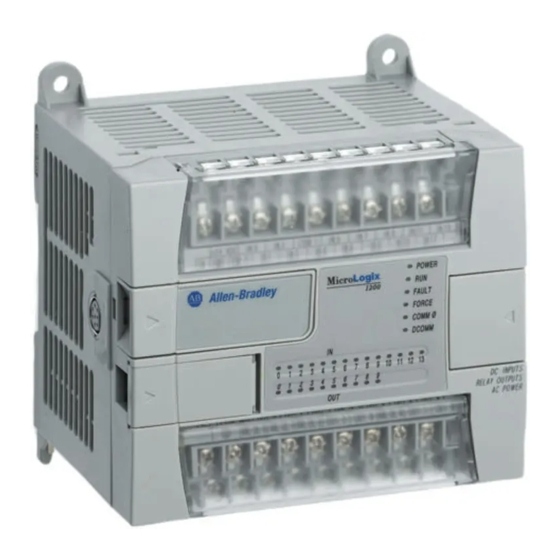
Page 6: Controller Description
MicroLogix™ 1200 Programmable Controllers Controller Description Feature Description Feature Description Terminal Blocks Terminal Doors and Label Bus Connector Interface to Trim Pots Expansion I/O Input LEDs Default Communications Push Button Output LEDs Memory Module Port Cover -or- Communication Port Memory Module and/or Real Time Clock (Channel 0) Status LEDs DIN Rail Latches... -
Page 7: Hazardous Location Considerations
MicroLogix™ 1200 Programmable Controllers Hazardous Location Considerations This equipment is suitable for use in Class I, Division 2, Groups A, B, C, D or non-hazardous locations only. The following ATTENTION statement applies to use in hazardous locations. ATTENTION: EXPLOSION HAZARD •... -
Page 8: Mounting The Controller
MicroLogix™ 1200 Programmable Controllers Mounting the Controller General Considerations Most applications require installation in an industrial enclosure to reduce the effects of electrical interference and environmental exposure. Locate your controller as far as possible from power lines, load lines, and other sources of electrical noise such as hard-contact switches, relays, and AC motor drives. -
Page 9: Mounting Dimensions
MicroLogix™ 1200 Programmable Controllers Mounting Dimensions 1762-L24AWA, 1762-L24BWA 1762-L40AWA, 1762-L40BWA Dimension 1762-L24AWA 1762-L24BWA 1763-L40AWA 1762-L40BWA 90 mm (3.5 in.) 90 mm (3.5 in.) 110 mm (4.33 in.) 160 mm (6.30 in.) 87 mm (3.43 in.) 87 mm (3.43 in.) Controller Spacing The controller mounts horizontally, with the expansion I/O extending to the right of the controller. - Page 10 MicroLogix™ 1200 Programmable Controllers DIN Rail Mounting The maximum extension of the latch is 14 mm (0.55 in.) in the open position. A flat-blade screwdriver is required for removal of the controller. The controller can be mounted to EN50022-35x7.5 or EN50022-35x15 DIN rails. DIN rail mounting dimensions are shown below.
-
Page 11: Panel Mounting
MicroLogix™ 1200 Programmable Controllers To remove your controller from the DIN rail: 1. Place a flat-blade screwdriver in the DIN rail latch at the bottom of the controller. 2. Holding the controller, pry downward on the latch until the latch locks in the open position. -
Page 12: Connecting 1762 I/O Expansion Modules
Ensure that your system power supply is sufficient to support the number of I/O modules you are installing in the system. A system loading worksheet is provided in the MicroLogix 1200 Programmable Controllers User Manual, publication 1762-UM001A-US-P. For detailed information on using expansion I/O, refer to the installation instructions for your expansion module. -
Page 13: Wiring The Controller
MicroLogix™ 1200 Programmable Controllers Wiring the Controller Note: The shading in the following terminal block illustrations indicates which terminals are tied to which commons. 1762-L24BWA Terminal Block Layout IN 0 IN 2 IN 5 IN 7 IN 9 IN 11 IN 13 IN 1 IN 3 IN 4... - Page 14 MicroLogix™ 1200 Programmable Controllers Wire Requirements Wire Type Wire Size (2 wire maximum per terminal screw) Solid Cu-90°C (194°F) #14 to #22 AWG Stranded Cu-90°C (194°F) #16 to #22 AWG Wiring torque = 0.791 Nm (7 in-lb) rated ATTENTION: Be careful when stripping wires. Wire fragments that fall into the controller could cause damage.
- Page 15 Spade Lug Recommendation The diameter of the terminal screw head is 5.5 mm (0.220 in.). The input and output terminals of the MicroLogix 1200 controller are designed for the following spade lugs. The terminals will accept a 6.35mm (0.25 in.) wide spade (standard for #6 screw for up to 14 AWG) or a 4 mm (metric #4) fork terminal.
- Page 16 MicroLogix™ 1200 Programmable Controllers Grounding the Controller In solid-state control systems, grounding and wire routing helps limit the effects of noise due to electromagnetic interference (EMI). Run the ground connection from the ground screw of the controller to the ground bus prior to connecting any devices.
-
Page 17: General Specifications
MicroLogix™ 1200 Programmable Controllers Specifications General Specifications Description 1762-L24AWA 1762-L24BWA 1762-L40AWA 1762-L40BWA Dimensions Height: 90 mm Height: 90 mm 104 mm (with DIN latch open) 104 mm (with DIN latch open) Width: 110 mm Width: 160 mm Depth: 87 mm Depth: 87 mm Shipping Weight 0.9 kg (2.0 lbs) 1.1 kg (2.4 lbs) - Page 18 MicroLogix™ 1200 Programmable Controllers Description 1762-L24AWA 1762-L24BWA 1762-L40AWA 1762-L40BWA Agency • UL 508 Certification • C-UL under CSA C22.2 no. 142 • Class I, Div. 2, Groups A, B, C, D (UL 1604, C-UL under CSA C22.2 no. 213) • CE compliant for all applicable directives Electrical/EMC The controller has passed testing at the following levels: IEC1000-4-2: 4 kV contact, 8 kV air, 4 kV indirect...
- Page 19 MicroLogix™ 1200 Programmable Controllers Output Specifications - Maximum Continuous Current Specification 1762-L24AWA, 1762-L40AWA, 1762-L24BWA 1762-L40BWA Current per Common Current per Controller at 150V max at 240V max (1) 15A above 40°C (2) 24A above 40°C Relay Contact Rating Table Maximum Volts Amperes Amperes Volt-Amperes...
- Page 20 MicroLogix™ 1200 Programmable Controllers Working Voltage (1762-L24AWA, 1762-L40AWA) Specification 1762-L24AWA, 1762-L40AWA Power Supply Input to Backplane Verified by one of the following dielectric tests: 1836V ac Isolation for 1 second or 2596V dc for 1 second 265V ac Working Voltage (IEC Class 2 reinforced insulation) Input Group to Backplane Isolation Verified by one of the following dielectric tests:1517V ac and Input Group to Input Group...
- Page 21 Notice d'installation Section française Automates programmables MicroLogix™ 1200 (Réf. 1762-L24AWA, 1762-L24BWA, 1762-L40AWA, 1762-L40BWA) Sommaire . . . Pour en savoir plus ............. 22 Introduction ................ 23 Description de l'automate ........... 24 Considérations relatives aux environnements dangereux ..25 Montage de l'automate ............26 Connexion des modules d'extension d'E/S 1762 ....
-
Page 22: Pour En Savoir Plus
MicroLogix™ 1500 Instruction fonctions, un jeu d'instructions et Set Reference Manual des informations de dépannage relatifs à MicroLogix 1200 et MicroLogix 1500. Informations relatives à l'installation MicroLogix™ 1762-IA8 120 V ac 1762-IN002A-US-P et l'utilisation du module d'extension Input Module Installation Instruc- d'E/S 1762-IA8. -
Page 23: Introduction
Automates programmables MicroLogix™ 1200 Introduction Les automates MicroLogix™ 1200 conviennent à une utilisation en milieu industriel lorsqu'ils sont installés conformément aux présentes instructions. Plus précisément, ces appareils sont destinés à une utilisation dans des environnements propres et secs (pollution de niveau 2 ) et à... -
Page 24: Description De L'automate
Automates programmables MicroLogix™ 1200 Description de l'automate Description Description Borniers Cache-bornes et étiquette Interface du connecteur Potentiomètres de compensation bus vers le module d'extension d'E/S Voyants d'entrées Bouton-poussoir Communications défaut Voyants de sorties Couvercle du port de module mémoire -ou- module mémoire et/ou horloge en temps Port de communication (Canal 0) réel... -
Page 25: Considérations Relatives Aux Environnements Dangereux
Automates programmables MicroLogix™ 1200 Considérations relatives aux environnements dangereux Cet équipement ne convient qu’à une utilisation en environnements de Classe I, Division 2, Groupes A, B, C, D ou non dangereux. L'avertissement suivant concerne l'utilisation en environnements dangereux. ATTENTION : RISQUE D'EXPLOSION •... -
Page 26: Montage De L'automate
Automates programmables MicroLogix™ 1200 Montage de l'automate Considérations générales La plupart des applications nécessitent d'être installées dans une armoire industrielle afin de réduire les effets dus aux interférences électriques et à l'environnement. Placer l'automate le plus loin possible des lignes électriques, lignes de charge, ou de toute autre source de parasites électriques telles que les interrupteurs à... -
Page 27: Dimensions De Montage
Automates programmables MicroLogix™ 1200 Dimensions de montage 1762-L24AWA, 1762-L24BWA 1762-L40AWA, 1762-L40BWA Dimension 1762-L24AWA 1762-L24BWA 1762-L40AWA 1762-L40BWA 90 mm (3,5 in.) 90 mm (3,5 in.) 110 mm (4,33 in.) 160 mm (6,30 in.) 87 mm (3,43 in.) 87 mm (3,43 in.) Espacement autour du contrôleur L'automate est monté... -
Page 28: Montage Sur Rail Din
Automates programmables MicroLogix™ 1200 Montage sur rail DIN L'extension maximum du verrou est de 14 mm (0,55 in.) en position ouvert. Un tournevis à lame plate est nécessaire afin de retirer l'automate. Celui-ci peut être monté sur des rails DIN EN50022-35x7,5 ou EN50022-35x15. Les dimensions de montage sur rails DIN sont indiquées ci-après. -
Page 29: Montage Sur Panneau
Automates programmables MicroLogix™ 1200 Pour retirer votre automate du rail DIN : 1. Placer un tournevis à lame plate dans le verrou du rail DIN sur la partie inférieure de l'automate. 2. Tout en maintenant l'automate, exercer une action de levier vers le bas sur le verrou jusqu'à... -
Page 30: Connexion Des Modules D'extension D'e/S 1762
Vérifier que le bloc d'alimentation du système est suffisant pour recevoir le nombre de modules d'E/S installés dans le système. Le Manuel d'utilisation de l'automate programmable MicroLogix 1200, publication 1762-UM001A-US-P, contient une fiche de calcul de la charge du système. -
Page 31: Câblage De L'automate
Automates programmables MicroLogix™ 1200 Câblage de l'automate Remarque : L'ombrage figurant dans les illustrations de borniers suivantes indique quelles bornes sont reliées à quels communs. Disposition du bornier 1762-L24BWA IN 0 IN 2 IN 5 IN 7 IN 9 IN 11 IN 13 IN 1 IN 3 IN 4... -
Page 32: Spécifications Relatives Aux Fils
Automates programmables MicroLogix™ 1200 Spécifications relatives aux fils Type de fil Calibre des fils (2 fils maximum par vis de borne) Plein Cu-90 °C N° 14 à N° 22 AWG Torsadé Cu-90 °C N° 16 à N° 22 AWG Couple de câblage = 0,791 Nm (7 in-lb) nominal ATTENTION : Faire attention en dénudant les fils. -
Page 33: Protection Contre Les Surtensions
Le diamètre de la tête de la vis de borne est de 5,5 mm (0.220 in.). Les bornes d'entrée et de sortie de l'automate MicroLogix 1200 sont conçues pour les cosses suivantes. Les bornes acceptent des cosses d'une largeur de 6,35 mm (standard de la vis n°... -
Page 34: Mise À La Terre De L'automate
Automates programmables MicroLogix™ 1200 Mise à la terre de l'automate Dans les commandes électroniques, la mise à la terre et l'acheminement des fils permet de limiter les effets des perturbations dues aux interférences électromag- nétiques (EMI). Faire passer la connexion de mise à la terre depuis la vis de masse de l'automate vers la barre de terre avant de connecter tout autre appareil. -
Page 35: Caractéristiques Techniques
Automates programmables MicroLogix™ 1200 Caractéristiques techniques Spécifications générales Description 1762-L24AWA 1762-L24BWA 1762-L40AWA 1762-L40BWA Dimensions Hauteur : 90 mm Hauteur : 90 mm 104 mm (avec verrou DIN ouvert) 104 mm (avec verrou DIN ouvert) Largeur : 110 mm Largeur : 160 mm Profondeur : 87 mm Profondeur : 87 mm Poids à... -
Page 36: Spécifications D'entrée
Automates programmables MicroLogix™ 1200 Description 1762-L24AWA 1762-L24BWA 1762-L40AWA 1762-L40BWA • UL 508 Homologations • C-UL sous CSA C22.2 n° 142 • Classe I, Div. 2, Groupes A, B, C, D (UL 1604, C-UL sous CSA C22.2 n° 213) • Conforme à toutes les directives CE applicables Électricité/ Le contrôleur a satisfait aux tests aux niveaux suivants : Compatibilité... -
Page 37: Spécifications De Sortie - Courant Continu Maximum
Automates programmables MicroLogix™ 1200 Spécifications de sortie – Courant continu maximum Spécifications 1762-L24AWA, 1762-L40AWA, 1762-L24BWA 1762-L40BWA Courant par commun Courant par automate à 150 V (max.) 30 A 23 A à 240 V (max.) 20 A 20 A (1) 15 A au-dessus de 40 °C (104 °F) (2) 24 A au-dessus de 40 °C (104 °F) Table de puissance des contacts relais Tension... - Page 38 Automates programmables MicroLogix™ 1200 Tension de fonctionnement (1762-L24AWA, 1762-L40AWA) Spécification 1762-L24AWA, 1762-L40AWA Isolation entre entrée du bloc Vérifiée au moyen de l'un des tests diélectriques suivants : d'alimentation et fond de panier 1836 V c.a. pendant 1 seconde ou 2596 V c.c. pendant 1 seconde Tension de fonctionnement 265 V c.a.
- Page 39 Installationsanleitung Deutscher Abschnitt Speicherprogrammierbare Steuerungen MicroLogix™ 1200 (Kat. Nr. 1762-L24AWA, 1762-L24BWA, 1762-L40AWA, 1762-L40BWA) Inhalt . . . Weitere Informationen ........40 Überblick ............41 Beschreibung des Steuergeräts ....42 Explosionsgefährdete Standorte ....43 Montage des Steuergeräts ......44 1762 E/A-Erweiterungsmodul anschließen ..48 Verdrahtung des Steuergeräts .......
-
Page 40: Weitere Informationen
Ein Referenzhandbuch, das Daten- MicroLogix™ 1200 and 1762-RM001A-US-P und Programmdateien, Befehlssatz MicroLogix™ 1500 Instruction und Informationen zur Fehlersuche Set Reference Manual für MicroLogix 1200 und MicroLogix 1500 enthält. Informationen über Einbau und MicroLogix™ 1762-IA8 120V ac 1762-IN002A-US-P Verwendung des 1762-IA8 Input Module Installation E/A-Erweiterungsmoduls. -
Page 41: Überblick
Speicherprogrammierbare Steuerungen MicroLogix™ 1200 Überblick MicroLogix™ 1200 Steuerungen eignen sich für den Einsatz in einer industri- ellen Umgebung, sofern sie entsprechend dieser Anleitung eingebaut werden. Dieses Gerät ist speziell für die Verwendung in einer sauberen, trockenen Umgebung (Verschmutzung des Grades 2 ) und in Stromkreisen bis maximal Überspannung der Kategorie II (IEC 60664-1) gedacht. -
Page 42: Beschreibung Des Steuergeräts
Speicherprogrammierbare Steuerungen MicroLogix™ 1200 Beschreibung des Steuergeräts Merk- Beschreibung Merk- Beschreibung Klemmenleisten Status LEDs Busstecker-Schnittstelle Klemmenleistendeckel und Aufkleber zur E/A-Erweiterung Trimmerwiderstand Eingangs-LEDs Taster, Standardeinstellung Kommunikation Ausgangs-LEDs Deckel, Speichermodulschacht -oder Speichermodul und/oder Echtzeituhr (RTC) Kommunikationsanschluß DIN-Schienenklinken (Kanal 0) (1) Mit Steuergerät geliefert (2) Wahlweise Zusatzausrüstung. -
Page 43: Explosionsgefährdete Standorte
Speicherprogrammierbare Steuerungen MicroLogix™ 1200 Explosionsgefährdete Standorte Dieses Gerät ist nur für die Aufstellung an Standorten der Klasse I, Abteilung 2, Gruppen A, B, C, D bzw. für die Aufstellung an nicht explosionsgefährdeten Standorten ausgelegt. Der folgende WARNHINWEIS ist beim Betrieb an explosionsgefährdeten Standorten zu beachten. -
Page 44: Montage Des Steuergeräts
Speicherprogrammierbare Steuerungen MicroLogix™ 1200 Montage des Steuergeräts Allgemeine Überlegungen Die meisten Anwendungen erfordern eine Installation in einem Industriegehäuse (Schrank), um die Einwirkung elektrischer Störungen und Umwelteinflüsse zu minimieren. Das Steuergerät ist in möglichst großem Abstand von Netzstromlei- tungen und anderweitigen Störungsquellen (wie Schaltkontakten, Relais und AC-Motorantrieben) zu positionieren. - Page 45 Speicherprogrammierbare Steuerungen MicroLogix™ 1200 Einbaumaße 1762-L24AWA, 1762-L24BWA 1762-L40AWA, 1762-L40BWA Maß 1762-L24AWA 1762-L24BWA 1762-L40AWA 1762-L40BWA 90 mm (3,5 Zoll) 90 mm (3,5 Zoll) 110 mm (4,33 Zoll) 160 mm (6,30 Zoll) 87 mm (3,43 Zoll) 87 mm (3,43 Zoll) Steuergerät-Abstände Das Steuergerät wird waagerecht eingebaut, wobei sich die E/A-Erweiterung rechts vom Steuergerät befindet.
- Page 46 Speicherprogrammierbare Steuerungen MicroLogix™ 1200 Montage an einer DIN-Schiene Die maximale Ausladung der Klinke beträgt 14 mm (0,55 Zoll) in der offenen Stellung. Für den Ausbau des Steuergeräts ist ein Schraubendreher mit flacher Klinge erforderlich. Das Steuergerät kann auf DIN-Schienen des Typs EN50022-35x7.5 oder EN50022-35x15 montiert werden.
- Page 47 Speicherprogrammierbare Steuerungen MicroLogix™ 1200 Steuergerät von der DIN-Schiene entfernen: 1. In die DIN-Schienenklinke auf der Unterseite des Steuergeräts einen Schraubendreher mit flacher Klinge einführen. 2. Steuergerät festhalten, Klinke nach unten stemmen, bis sie in der offenen Stellung einrastet. 3. Schritt 1 und 2 an der zweiten DIN-Schienenklinke wiederholen. 4.
-
Page 48: 1762 E/A-Erweiterungsmodul Anschließen
Sicherstellen, daß die Kapazität der Stromversorgung für die Anzahl der im System eingebauten E/A-Module ausreicht. Ein Arbeitsblatt zur Berechnung der Systemlast befindet sich im Benutzerhandbuch der speicherprogrammierbaren Steuerung MicroLogix 1200, Publikation 1762-UM001A-US-P. Ausführliche Informationen über die Verwendung der E/A-Erweiterungen siehe Installationsanleitung für das jeweilige Erweiterungsmodul. -
Page 49: Verdrahtung Des Steuergeräts
Speicherprogrammierbare Steuerungen MicroLogix™ 1200 Verdrahtung des Steuergeräts Hinweis: Die Schattierungen der unten aufgeführten Klemmenleistendarstel- lungen zeigen auf, welche Klemmen an den unterschiedlichen Bezug- spotentialen angeschlossen sind. 1762-L24BWA Klemmenleisten-Layout IN 0 IN 2 IN 5 IN 7 IN 9 IN 11 IN 13 IN 1 IN 3 IN 4... - Page 50 Speicherprogrammierbare Steuerungen MicroLogix™ 1200 Kabelanforderungen Art des Drahtes Drahtstärke (max. 2 Drähte je Klemmenschraube) Massiv Cu-90 °C 14 bis 22 AWG Verseilt Cu-90 °C 16 bis 22 AWG Anziehdrehmoment = 0,791 Nm nominal ACHTUNG: Seien Sie vorsichtig beim Abisolieren von Kabeln. Drahtpartikel, die in das Innere des Steuergeräts gelangen, könnten Schäden verursachen.
- Page 51 Kabelschuh-Empfehlung Der Durchmesser des Klemmenschraubenkopfs beträgt 5,5 mm (0,220 Zoll). Eingangs- und Ausgangsklemmenleisten des MicroLogix 1200 Steuergeräts sind für folgende Kabelschuhe ausgelegt. Für die Klemmen paßt ein 6,35 mm breiter Kabelschuh (Standard für Schraubendurchmesser Nr. 6 bis 14 AWG) oder ein 4 mm (metrisch Nr.
- Page 52 Speicherprogrammierbare Steuerungen MicroLogix™ 1200 Erdung des Steuergeräts In elektronischen Steuerungen tragen Erdung und korrekte Drahtverlegung wesentlich zur Reduzierung des durch elektromagnetische Störungen (EMI) verursachten Rauschens bei. Bevor irgendwelche Geräte/Komponenten angeschlossen werden, ist die Erdungsverbindung von der Masseschraube des Steuergeräts zur Erdschiene zu erstellen. Draht AWG-Stärke Nr. 14 verwenden. Diese Verbindung ist aus sicherheitstechnischen Gründen zu erstellen.
-
Page 53: Allgemeine Technische Daten
Speicherprogrammierbare Steuerungen MicroLogix™ 1200 Technische Daten Allgemeine technische Daten Beschreibung 1762-L24AWA 1762-L24BWA 1762-L40AWA 1762-L40BWA Abmessungen Höhe 90 mm Höhe 90 mm 104 mm (DIN-Schienenklinke offen) 104 mm (DIN-Schienenklinke offen) Breite: 110 mm Breite: 160 mm Tiefe: 87 mm Tiefe: 87 mm Versandgewicht 0,9 kg 1,1 kg... - Page 54 Speicherprogrammierbare Steuerungen MicroLogix™ 1200 Beschreibung 1762-L24AWA 1762-L24BWA 1762-L40AWA 1762-L40BWA • Amtliche UL 508 • Zertifizierung C-UL unter CSA C22.2 Nr. 142 • Klasse I, Abt. 2, Gruppen A, B, C, D (UL 1604, C-UL unter CSA C22.2 Nr. 213) • Erfüllt alle anwendbaren CE-Richtlinien Elektrische Das Steuergerät hat folgende Prüfungen durchlaufen:...
- Page 55 Speicherprogrammierbare Steuerungen MicroLogix™ 1200 Ausgangsspezifikationen – Maximaler Dauerstrom Technische Daten 1762-L24AWA, 1762-L40AWA, 1762-L24BWA 1762-L40BWA Strom je Bezugspotential Strom je Steuergerät bei 150 V (max.) 30 A 23 A bei 240 V (max.) 20 A 20 A (1) 15A über 40°C (2) 24A über 40°C Relaiskontakte, Belastungstabelle Maximalspannung...
- Page 56 Speicherprogrammierbare Steuerungen MicroLogix™ 1200 Arbeitsspannung (1762-L24AWA, 1762-L40AWA) Spezifikation 1762-L24AWA, 1762-L40AWA Netzteil-Eingang zu Geprüft durch einen der folgenden dielektrischen Tests: Backplane-Isolierung 1836 V AC für 1 Sekunde oder 2596 V DC für 1 Sekunde 265 V AC Arbeitsspannung (verstärkte Isolierung nach IEC Klasse 2) Eingangsgruppe zu Geprüft durch einen der folgenden dielektrischen Tests:...
-
Page 57: Istruzioni Per L'installazione
Istruzioni per l'installazione Sezione italiana Controllori programmabili MicroLogix™ 1200 (No. Cat. 1762-L24AWA, 1762-L24BWA, 1762-L40AWA, 1762-L40BWA) Sommario: Per ulteriori informazioni ..........58 Panoramica del prodotto ..........59 Descrizione del controllore ........... 60 Considerazioni sugli ambienti pericolosi ....... 61 Montaggio del controllore ..........62 Connessione dei moduli di espansione I/O 1762 .. -
Page 58: Per Ulteriori Informazioni
MicroLogix™ 1500 Instruction istruzioni e informazioni sulla Set Reference Manual ricerca guasti per i controllori MicroLogix 1200 e MicroLogix 1500. Informazioni sull'installazione e MicroLogix™ 1762-IA8 120 V ac 1762-IN002A-US-P l'utilizzo del modulo I/O di Input Module Installation espansione 1762-IA8. -
Page 59: Panoramica Del Prodotto
Controllori programmabili MicroLogix™ 1200 Panoramica del prodotto I controllori MicroLogix™ 1200 sono adatti per l'uso in un ambiente industriale se installati attenendosi alle seguenti istruzioni. In particolare, questo dispositivo è progettato per essere impiegato in ambienti asciutti e puliti (grado di inquina- mento 2 ) ed in circuiti che non superano la Classe di sovratensione II (IEC... -
Page 60: Descrizione Del Controllore
Controllori programmabili MicroLogix™ 1200 Descrizione del controllore Numero Descrizione Numero Descrizione Morsettiere Sportelli ed etichetta dei morsetti Interfaccia connettore Potenziometri regolazione fine bus all'I/O di espansione LED di ingresso Pulsante per le comunicazioni preimpostato LED di uscita Coperchio porta modulo di memoria modulo di memoria e/o orologio in tempo Porta di comunicazione reale... -
Page 61: Considerazioni Sugli Ambienti Pericolosi
Controllori programmabili MicroLogix™ 1200 Considerazioni sugli ambienti pericolosi Questo dispositivo può essere utilizzato solo in ambienti appartenenti alla Classe I, Divisione 2, Gruppi A, B, C, D oppure in ambienti non pericolosi. Il seguente messaggio di ATTENZIONE concerne l'uso in ambienti pericolosi. ATTENZIONE: RISCHIO D'ESPLOSIONE •... -
Page 62: Montaggio Del Controllore
Controllori programmabili MicroLogix™ 1200 Montaggio del controllore Considerazioni generali La gran parte delle applicazioni richiede di essere installata in una custodia industriale al fine di ridurre gli effetti di interferenze elettriche o dell'esposizione ambientale. Posizionare il controllare il più lontano possibile da linee di alimen- tazione, linee di carico ed altre fonti di interferenze elettriche quali interruttori a contatto elettromeccanico, relè... - Page 63 Controllori programmabili MicroLogix™ 1200 Dimensioni per il montaggio 1762-L24AWA, 1762-L24BWA 1762-L40AWA, 1762-L40BWA Dimensione 1762-L24AWA 1762-L24BWA 1762-L40AWA 1762-L40BWA 90 mm (3,5 poll.) 90 mm (3,5 poll.) 110 mm (4,33 poll.) 160 mm (6,30 poll.) 87 mm (3,43 poll.) 87 mm (3,43 poll.) Spazio necessario per il controllore Il controllore viene montato orizzontalmente, con il modulo I/O di espansione che fuoriesce dal lato destro del controllore.
- Page 64 Controllori programmabili MicroLogix™ 1200 Montaggio della guida DIN L'estensione massima dell'innesto è 14 mm (0,55 poll.) in posizione d'apertura. Per rimuovere il controllore è necessario un cacciavite a lama piatta. Il controllore può essere montato su guide DIN EN50022-35x7.5 o EN50022-35x15. Le dimensioni per il montaggio delle guide DIN sono riportate di seguito.
- Page 65 Controllori programmabili MicroLogix™ 1200 Per rimuovere il controllore dalla guida DIN: 1. Inserire un cacciavite a lama piatta nell'innesto della guida DIN posto sul lato inferiore del controllore. 2. Tenendo fermo il controllore, fare leva verso il basso sull'innesto fino a che questo non si blocca in posizione di apertura.
-
Page 66: Connessione Dei Moduli Di Espansione I/O 1762
è fornito nel manuale per utente dei Controllori Programmabili MicroLogix 1200, pubblicazione 1762-UM001A-US-P. Per informazioni dettagliate sull'utilizzo dei moduli I/O di espansione, fare riferimento alle istruzioni per l'installazione del modulo di espansione in uso. -
Page 67: Cablaggio Del Controllore
Controllori programmabili MicroLogix™ 1200 Cablaggio del controllore Nota: Nelle illustrazioni delle morsettiere di seguito riportate, l'ombreggia- tura indica la connessione dei morsetti alle relative masse comuni. Schema della morsettiera del 1762-L24BWA IN 0 IN 2 IN 5 IN 7 IN 9 IN 11 IN 13 IN 1 IN 3... - Page 68 Controllori programmabili MicroLogix™ 1200 Requisiti di cablaggio Tipo di filo Dimensione filo (2 fili max. per vite del morsetto) Rigido Cu-90 °C (194 °F) da n. 14 a n. 22 AWG A treccia Cu-90 °C (194 °F) da n. 16 a n. 22 AWG Coppia di serraggio = 0,791 Nm (7 poll.-lb) nominale ATTENZIONE: Fare attenzione durante lo spellamento dei fili.
- Page 69 Il diametro della testa della vite del morsetto è 5,5 mm (0,220 poll.). I morsetti di ingresso e di uscita del controllore MicroLogix 1200 sono progettati per i seguenti capicorda a forcella. La dimensione dei capicorda idonea per i morsetti è 6,35 mm (0,25 poll.) (standard per vite n.
- Page 70 Controllori programmabili MicroLogix™ 1200 Messa a terra del controllore Nei sistemi di controllo allo stato solido, la messa a terra e l'instradamento dei cavi contribuisce a limitare gli effetti delle interferenze dovute a disturbi elettromagnetici (EMI). Eseguire la connessione fase-terra dalla vite di terra del controllore al bus di terra prima di connettere qualsiasi dispositivo.
-
Page 71: Caratteristiche
Controllori programmabili MicroLogix™ 1200 Caratteristiche Caratteristiche generali Descrizione 1762-L24AWA 1762-L24BWA 1762-L40AWA 1762-L40BWA Dimensioni Altezza: 90 mm Altezza: 90 mm 104 mm (con innesto DIN aperto) 104 mm (con innesto DIN aperto) Larghezza: 110 mm Larghezza: 160 mm Profondità: 87 mm Profondità: 87 mm Peso di 0,9 kg (2,0 lb.) - Page 72 Controllori programmabili MicroLogix™ 1200 Descrizione 1762-L24AWA 1762-L24BWA 1762-L40AWA 1762-L40BWA • Certificazione UL 508 • C-UL secondo la norma CSA C22.2 N° 142 • Classe I, Div. 2, Gruppi A, B, C, D (UL 1604, C-UL secondo CSA C22.2 N° 213) •...
- Page 73 Controllori programmabili MicroLogix™ 1200 Caratteristiche delle uscite – Corrente continua massima Caratteristica 1762-L24AWA, 1762-L40AWA, 1762-L24BWA 1762-L40BWA Corrente per punto comune Corrente per controllore a 150 V (max.) 30 A 23 A a 240 V (max.) 20 A 20 A (1) 15 A oltre 40°C (104°F) (2) 24 A oltre 40°C (104°F) Tabella della potenza dei contatti a relè...
- Page 74 Controllori programmabili MicroLogix™ 1200 Tensione di esercizio (1762-L24AWA, 1762-L40AWA) Caratteristica 1762-L24AWA, 1762-L40AWA Isolamento tra ingresso Verificato da uno dei seguenti collaudi dielettrici: alimentazione e backplane 1836 V ca per 1 secondo o 2596 V cc per 1 secondo Tensione di esercizio 265 V ca (isolamento rinforzato IEC Classe 2) Isolamento tra gruppo di ingresso e Verificato da uno dei seguenti collaudi dielettrici:...
- Page 75 Instrucciones de instalación Sección en español Controladores programables MicroLogix™ 1200 (No. de cat. 1762-L24AWA, 1762-L24BWA, 1762-L40AWA, 1762-L40BWA) En el interior . . . Para obtener más información ...... 76 Descripción general ........77 Descripción del controlador ......78 Consideraciones sobre lugares peligrosos ..79 Montaje del controlador ........
-
Page 76: Para Obtener Más Información
MicroLogix™ 1500 Instruction conjunto de instrucciones e Set Reference Manual información para la resolución de problemas para MicroLogix 1200 y MicroLogix 1500. Información acerca de la instala- MicroLogix™ 1762-IA8 120V ac 1762-IN002A-US-P ción y uso del módulo de expansión Input Module Installation 1762-IA8 de E/S. -
Page 77: Descripción General
Controladores programables MicroLogix™ 1200 Descripción general Los controladores MicroLogix™ 1200 pueden usarse en entornos industriales siempre y cuando se instalen según las instrucciones siguientes. Específicamente, este equipo está concebido para ser empleado en entornos limpios y secos (grado de contaminación 2 ), y para ser conectado en circuitos que no excedan la Categoría de sobretensión II (IEC 60664-1). -
Page 78: Descripción Del Controlador
Controladores programables MicroLogix™ 1200 Descripción del controlador Característica Descripción Bloques de terminales Interface del conector de bus hacia las E/S expansoras Indicadores LED de entrada Indicadores LED de salida Puerto de comunicaciones (Canal 0) Indicadores LED de estado Puertas de terminales y etiqueta Potenciómetro Botón pulsador de comunicaciones predeterminadas Cubierta del puerto del módulo de memoria... -
Page 79: Consideraciones Sobre Lugares Peligrosos
Controladores programables MicroLogix™ 1200 Consideraciones sobre lugares peligrosos Este equipo es apropiado para uso en lugares Clase I, División 2, Grupos A, B, C, D o en lugares no peligrosos solamente. La siguiente nota de ATENCION rige para el uso en lugares peligrosos. ATENCION: PELIGRO DE EXPLOSION •... -
Page 80: Montaje Del Controlador
Controladores programables MicroLogix™ 1200 Montaje del controlador Consideraciones generales La mayoría de las aplicaciones deben estar instaladas en un entorno industrial a fin de reducir los efectos de la interferencia eléctrica y exposición ambiental. Coloque el controlador tan alejado como sea posible de líneas de alimentación eléctrica, líneas de carga y otras fuentes de ruido eléctrico como interruptores de contacto de cableado, relés y variadores de motor CA. - Page 81 Controladores programables MicroLogix™ 1200 Dimensiones para el montaje 1762-L24AWA, 1762-L24BWA 1762-L40AWA, 1762-L40BWA Dimensión 1762-L24AWA 1762-L24BWA 1762-L40AWA 1762-L40BWA 90 mm (3.5 pulg.) 90 mm (3.5 pulg.) 110 mm (4.33 pulg.) 160 mm (6.30 pulg.) 87 mm (3.43 pulg.) 87 mm (3.43 pulg.) Espacio entre controladores El controlador debe montarse horizontalmente de modo que las E/S expansoras estén situadas a la derecha del mismo.
- Page 82 Controladores programables MicroLogix™ 1200 Montaje en riel DIN La extensión máxima del seguro es de 14 mm (0.55 pulg.) en la posición abierta. Use un destornillador de punta plana para retirar el controlador. El controlador puede montarse en rieles DIN EN50022-35x7.5 ó EN50022-35 x15. A continuación se muestran las dimensiones para el montaje en rieles DIN.
-
Page 83: Montaje En Panel
Controladores programables MicroLogix™ 1200 Para retirar el controlador del riel DIN: 1. Posicione un destornillador de punta plana en el seguro del riel DIN que se encuentra en la parte inferior del controlador. 2. Sujete el controlador, presione el seguro hacia abajo hasta que se quede bloqueado en la posición abierta. -
Page 84: Conexión Del Módulo Expansor De E/S 1762
Asegúrese de que la alimentación eléctrica es suficiente para los módulos de E/S que se instalan en el sistema. El manual del usuario MicroLogix 1200 Programmable Controllers (Núm. de publicación 1762-UM001A-US-P), proporciona una hoja de trábajo que le ayuda a determinar cuanta energía puede cargar al sistema. -
Page 85: Cableado Del Controlador
Controladores programables MicroLogix™ 1200 Cableado del controlador Nota: El sombreado de las siguientes ilustraciones del bloque de terminales indica cómo se conectan los terminales a los terminales comunes. Configuración del bloque de terminales 1762-L24BWA IN 0 IN 2 IN 5 IN 7 IN 9 IN 11 IN 13... -
Page 86: Requisitos De Cableado
Controladores programables MicroLogix™ 1200 Requisitos de cableado Recomendación para el tipo de cable Tipo de cable Tamaño del cable (máximo de 2 cables por tornillo de terminal) Macizo Cu-90 °C de #14 a #22 AWG Trenzado Cu-90 °C de #16 a #22 AWG Par de cableado = nominal 0.791 Nm (7 pg-lb) ATENCION: Tenga cuidado al pelar los cables. - Page 87 Recomendación para la lengüeta de espada El diámetro de la cabeza del tornillo del terminal es de 5.5 mm (0.220 pulg.). Los terminales de entrada y salida del controlador MicroLogix 1200 están diseñados para acomodar las siguientes lengüetas de espada. Los terminales aceptan lengüetas de espada de 6.35 mm de ancho (estándar para tornillos #6 para un...
- Page 88 Controladores programables MicroLogix™ 1200 Conexión a tierra del controlador En los sistemas de control con semiconductores, la conexión a tierra y el encaminamiento del cableado ayudan a restringir los efectos del ruido causados por interferencias electromagnéticas (EMI). Extienda la conexión a tierra desde el tornillo de tierra del controlador hasta el bus de tierra antes de conectar cualquier otro dispositivo.
-
Page 89: Especificaciones
Controladores programables MicroLogix™ 1200 Especificaciones Especificaciones generales Descripción 1762-L24AWA 1762-L24BWA 1762-L40AWA 1762-L40BWA Dimensiones Altura 90 mm Altura 90 mm 104 mm (con seguro DIN abierto) 104 mm (con seguro DIN abierto) Anchura: 110 mm Anchura: 160 mm Profundidad: 87 mm Profundidad: 87 mm Peso a salida de 0,9 kg (2,0 libras) - Page 90 Controladores programables MicroLogix™ 1200 Descripción 1762-L24AWA 1762-L24BWA 1762-L40AWA 1762-L40BWA • Certificaciones UL 508 • Certificación C-UL según CSA C22.2 no. 142 • Clase I, división 2, grupos A, B, C, D (UL 1604, C-UL según CSA C22.2 no. 213) • Cumple con todas las directivas aplicables de CE Eléctricas/EMC El módulo ha superado las pruebas en los siguientes niveles:...
- Page 91 Controladores programables MicroLogix™ 1200 Especificaciones de salida – Corriente continua máxima Especificación 1762-L24AWA, 1762-L40AWA, 1762-L24BWA 1762-L40BWA Corriente por terminal común Corriente por controlador a 150 V (máx.) 30 A 23 A Corriente por controlador a 240 V (máx.) 20 A 20 A (1) 15 A sobre 40°C (104°F) (2) 24 A sobre 40°C (104°F)
- Page 92 Controladores programables MicroLogix™ 1200 Voltaje de funcionamiento (1762-L24AWA, 1762-L40AWA) Especificación 1762-L24AWA, 1762-L40AWA Entrada de la fuente de alimentación Verificado por una de las siguientes pruebas dieléctricas: 1836 VCA durante 1 segundo ó 2596 VCC durante 1 eléctrica a aislamiento de backplane segundo con 265 VCA de voltaje de funcionamiento (IEC clase 2 aislamiento reforzado)
-
Page 93: Instruções De Instalação
Instruções de Instalação Seção em Português Controladores Programáveis MicroLogix™ 1200 (Cód. Cat. 1762-L24AWA, 1762-L24BWA, 1762-L40AWA, 1762-L40BWA) Índice. . . Para mais informações ..........94 Visão Geral ..............95 Descrição do Controlador Lógico ........96 Considerações sobre Áreas Classíficadas ..... 97 Montando o Controlador Lógico ........ -
Page 94: Para Mais Informações
MicroLogix™ 1500 Instruction funções, conjunto de instruções e Set Reference Manual informações sobre a localização de falhas do MicroLogix 1200 e MicroLogix 1500. Informações sobre a instalação e o MicroLogix™ 1762-IA8 120 V ac 1762-IN002A-US-P uso do módulo de expansão de E/S... -
Page 95: Visão Geral
Controladores Programáveis MicroLogix™ 1200 Visão Geral Os Controladores MicroLogix™ 1200 são apropriados para uso em um ambiente industrial quando instalado de acordo com essas instruções. Especificamente, este equipamento foi projetado para uso em ambientes limpos e secos (grau de poluição 2 ) e para circuitos que não excedem a categoria II de sobretensão (IEC 60664-1). -
Page 96: Descrição Do Controlador Lógico
Controladores Programáveis MicroLogix™ 1200 Descrição do Controlador Lógico Recurso Descrição Recurso Descrição Bloco terminal Portas do terminal e etiqueta Conector de Interface para Potenciômetros de ajuste o Barramento de Expansão de E/S LEDs de entrada Botão para Configuração da Comunicação LEDs de saída Tampa da porta do módulo de memória -ou- módulo de memória e/ou relógio em... -
Page 97: Considerações Sobre Áreas Classíficadas
Controladores Programáveis MicroLogix™ 1200 Considerações sobre Áreas Classíficadas Este equipamento é apropriado para uso na Classe I, Divisão 2, Grupos A, B, C, D ou somente em áreas não classificadas. O seguinte aviso de ATENÇÃO aplica-se ao uso em áreas classificadas. ATENÇÃO: PERIGO DE EXPLOSÃO •... -
Page 98: Montando O Controlador Lógico
Controladores Programáveis MicroLogix™ 1200 Montando o Controlador Lógico Considerações Gerais A maioria das aplicaçãos requer uma instalação em um gabinete industrial para reduzir os efeitos de interferência elétrica e exposição ambiental. Coloque o seu controlador lógico o mais longe possível das linhas de alimentação e carga e de outras fontes de ruído elétrico como, por exemplo, interruptores de contato, relés e inversores de freqüência CA. -
Page 99: Dimensões De Montagem
Controladores Programáveis MicroLogix™ 1200 Dimensões de Montagem 1762-L24AWA, 1762-L24BWA 1762-L40AWA, 1762-L40BWA Dimensão 1762-L24AWA 1762-L24BWA 1762-L40AWA 1762-L40BWA 90 mm (3,5 pol.) 90 mm (3,5 pol.) 110 mm (4,33 pol.) 160 mm (6,30 pol.) 87 mm (3,43 pol.) 87 mm (3,43 pol.) Espaço para Montagem do Controlador Lógico O controlador lógico é... - Page 100 Controladores Programáveis MicroLogix™ 1200 Montagem no Trilho DIN A extensão máxima da trava é de 14 mm (0,55 pol.) na posição aberta. É necessária uma chave de fenda para remoção do controlador lógico. O controlador pode ser montado nos trilhos DIN EN50022-35x7.5 ou EN50022-35x15. As dimensões de montagem do trilho DIN são mostradas abaixo.
- Page 101 Controladores Programáveis MicroLogix™ 1200 Para remover o controlador do trilho DIN: 1. Coloque a chave de fenda na trava do trilho DIN na parte inferior do controlador. 2. Segurando o controlador, pressione a trava até que a mesma fique na posição aberta.
-
Page 102: Conectando Os Módulos De Expansão De E/S 1762
E/S instalados. Uma planilha para definição do carregamento do sistema é apresentada no Manual Do Usuário Do Micrologix 1200 (publicação 1762-UM001-US-P). Para informações detalhadas sobre a utilização da expansão de E/S, consulte as instruções de instalação do módulo de expansão. -
Page 103: Instalando A Fiação No Controlador Lógico
Controladores Programáveis MicroLogix™ 1200 Instalando a Fiação no Controlador Lógico Obs.: Os diferentes sombreados nas seguintes clustrações de blocos terminais indicam que pontos terminais lão interligados a que pontos comuns. Layout do Bloco Terminal 1762-L24BWA IN 0 IN 2 IN 5 IN 7 IN 9 IN 11 IN 13... - Page 104 Controladores Programáveis MicroLogix™ 1200 Requisitos para Fiação Recomendação do Tipo de Fio Tipo de Fio Bitola do Fio (máximo de 2 fios por cada parafuso do terminal) Sólido Cu-90 °C (194 °F) n. 14 a n. 22 AWG Torcido Cu-90 °C (194 °F) n.
- Page 105 Recomendação sobre a Fiação sem terminal O diâmetro da cabeça do parafuso do terminal é de 5,5 mm (0,220 pol.). Os terminais de entrada e saída do controlador lógico MicroLogix 1200 são projetados para os seguintes terminais de fiação. Serão aceitos terminais com a abertura de 6,35 mm (0,25 pol.) (padrão para parafuso n.
- Page 106 Controladores Programáveis MicroLogix™ 1200 Aterrando o Controlador Lógico Nos sistemas de controle de estado-sólido, o roteamento da fiação e do aterramento ajuda a limitar os efeitos de ruído, devido à interferência eletromagnética (EMI). Faça a conexão do terra, a partir do parafuso de aterramento do controlador até a barra do terra, antes de conectar quaisquer dispositivos.
-
Page 107: Especificações
Controladores Programáveis MicroLogix™ 1200 Especificações Especificações Gerais Descrição 1762-L24AWA 1762-L24BWA 1762-L40AWA 1762-L40BWA Dimensões Altura 90 mm Altura 90 mm 104 mm (com trava DIN aberta) 104 mm (com trava DIN aberta) Largura: 110 mm Largura: 160 mm Profundidade: 87 mm Profundidade: 87 mm Peso de 0.9 kg (2.0 lb.) - Page 108 Controladores Programáveis MicroLogix™ 1200 Descrição 1762-L24AWA 1762-L24BWA 1762-L40AWA 1762-L40BWA • Certificação UL 508 • C-UL sob CSA C22.2 nº 142 • Classe I, Div. 2, Grupos A, B, C, D (UL 1604, C-UL sob CSA C22.2 nº 213) • Cumpre todas as diretrizes aplicáveis da CE Elétrica (EMC) O controlador lógico foi testado nos seguintes níveis: IEC1000-4-2: 4 kV para contato, 8 kV ar, 4 kV indireto...
- Page 109 Controladores Programáveis MicroLogix™ 1200 Especificações de Saída – Corrente Contínua Máxima Especificações 1762-L24AWA, 1762-L40AWA, 1762-L24BWA 1762-L40BWA Corrente por Comum Corrente por Controlador à 150 V (máx.) 30 A 23 A Corrente por Controlador à 240 V (máx.) 20 A 20 A (1) 15 A acima de 40°C (104°F) (2) 24 A acima de 40°C (104°F) Tabela de Capacidades dos Contatos a Relé...
- Page 110 Controladores Programáveis MicroLogix™ 1200 Tensão de trabalho (1762-L24AWA, 1762-L40AWA) Especificações 1762-L24AWA, 1762-L40AWA Isolação entre a Entrada da Fonte de Verificado por um dos seguintes testes dielétricos: 1836 V Alimentação e Barramento ca durante 1 segundo ou 2596 V cc durante 1 segundo Tensão de trabalho 265 V ca (isolação reforçada IEC Classe 2) Isolação entre Grupos de Entradas e Verificado por um dos seguintes testes dielétricos: 1517 V...
- Page 111 1762-IN006A-ML-P...
- Page 112 160.0 mm 25.81 mm (6.299 in.) (1.016 in.) 145.8 mm (5.739 in.) 95.86 mm (3.774 in.) 0.164 DIN rail center line. Expansion I/O Ligne médiane du rail DIN. Mittellinie der DIN-Schiene. d'extension d'E/S Línea central del riel DIN. E/A - Linea centrale della guida DIN.
- Page 113 1762-IN006A-ML-P...
- Page 114 MicroLogix is a trademark of Rockwell Automation. MicroLogix est une marque déposée de Rockwell Automation. MicroLogix ist ein Warenzeichen der Rockwell Automation. MicroLogix è un marchio di fabbrica della Rockwell Automation. MicroLogix es una marca comercial de Rockwell Automation. MicroLogix é uma marca registrada da Rockwell Automation. Publication 1762-IN006A-ML-P - January 2000 PN 40072-073-01(A) ©...