Publicité

Les langues disponibles

Les langues disponibles

Liens rapides

EN
738r
NL
Fr
Issue 2
It
1

Publicité

Table des Matières
loading

Sommaire des Matières pour Eaton Spyder 738r

  • Page 1 738r Issue 2...
  • Page 2 This product complies with the requirements of European Directive: 1995/5/EC (Radio &Telecommunications Terminal Equipment Directive). Ce produit est conforme aux exigences de la directive européenne : 1995/5/EC (Equipements terminaux de radio et de télécommunication). Dit product is conform de normen van de Europese Richtlijn 1995/5/EC (R&TTE Richtlijn) Questo prodotto è...
  • Page 3: Technical Specification

    The 738r Radio Spyder is a vibration and shock sensor capable of transmitting alarm infor- mation using Eaton’s Security Business’s 868MHz narrow band technology. The 738r can report to any compatible Eaton’s Security Business receiver. The receivers can learn the unique identity of each 738r through either an infra-red LED or radio transmissions.
  • Page 4 Figure 1 shows the external appearance and internal layout of the 738r. Figure 2 shows the indicators and controls on the 738r’s printed circuit board. 1. Activity LED 2. Cover screw 3. Aerial 4. Transmitter module 5. Battery Fig. 1...
  • Page 5 1. Activity/Learn LED 2. VR1. Sensitivity potentiometer 3. Lid tamper switch 4. Calibration LED 5. Battery 6. Back tamper switch 7. Mode jumpers Fig. 2...
  • Page 6: Compatible Equipment

    Compatible Equipment 762r Two channel receiver 768r/769r Eight channel receiver 790rEUR-00 Signal Strength Meter 9955/9960 Radio Frequency Expanders Homelink 75 Domestic Radio Control Unit Installation Siting To ensure the radio transmitter works correctly, do NOT mount the unit: Near the floor. Close to or on large metal structures.
  • Page 7 Fig. 3 Fig. 4 Note: Range shown for guidance only. Sensitivity may vary on different surfaces.
  • Page 8: Preparing For Installation

    Preparing for Installation 1. Open the case by removing the cover screw and pivoting the cover up from the bottom. 2. Remove the PCB by sliding the PCB up out of the PCB brackets. 3. Install one 3V CR2 Li/MnO2 battery (supplied) in the battery holder on the PCB. Learning 1.
  • Page 9 Commissioning The 738r has several different operating modes. To select the required mode you must place the jumpers as follows: Jumper Function Sensitivity Range Selection Jumper A selects the high or low sensitivity range. Fit the jumper to select the low sensitivity range.
  • Page 10 Fig. 5 Fig. 6 Fig. 8 Fig. 7...
  • Page 11 Example Jumper Settings Reduced Sensitivity (see Fig 5). Use on: hardwood or metal window and door frames, or on masonry walls. Normal (see Fig 6). Use on: softwood or plastic window and door frames, where there is excess paint, a long distance from glass, or around large glass windows. Note that this is the default setting when the 738r is delivered from the factory.
  • Page 12 5. Remove the sensitivity link (jumper A) if the sensor is unable to detect shocks from the whole of the area you wish to guard. 6. Remove the calibration link (jumper C) once you have achieved the desired sensitivity. This places the 738r in its normal operating mode.
  • Page 13: Battery Care

    Maintenance Eaton’s Security Business recommends that you regularly check the calibration of the 738r, see Commissioning. Change the battery every 24 months, or when the control unit indicates low detector bat- tery. The 738r indicates low battery by sending a message to the receiver. In addition, the Activ- ity LED will not operate if the battery is low (even if jumper D is removed).
  • Page 14 Every effort has been made to ensure that the contents of this leaflet are correct . How- ever, neither the authors nor Eaton’s Security Business accept any liability for loss or dam- age caused or alleged to be caused directly or indirectly by this leaflet. The contents of this leaflet are subject to change without notice.
  • Page 15: Technische Specificaties

    Introductie De draadloze Spyder 738r is een trilling- en schokdetector die de alarminformatie via de 868MHz smalband technologie van Eaton’s Security Business kan verzenden. De draadloze Spyder kan naar elke 7xx ontvanger, of 9960 draadloze uitbreiding, of naar de Homelink 75 van Eaton’s Security Business rapporteren. De ontvangers kunnen de unieke identiteit van elke Spyder leren door middel van een infrarood LED of draadloze data overdracht.
  • Page 16 Afbeelding 1 toont het uiterlijk van de Spyder. Afbeelding 2 toont de LED’s en de regelaars op het PCB van de Spyder. 1. Activiteiten-LED 2. Bevestigingsschroef 3. Antenne 4. Zendmodule 5. Batterij Fig. 1...
  • Page 17 1. Activiteiten-/Leer-LED 2. VR1. Gevoeligheidspotentiometer 3. Sabotageschakelaar deksel 4. Calibratie-LED 5. Batterij 6. Sabotageschakelaar rug 7. Brugschakelaars Fig. 2...
  • Page 18: Installatie

    Aanverwante apparatuur 762r Twee-kanaals ontvanger 768r/769r Acht-kanaals ontvanger 790rEUR-00 Veldsterktemeter Homelink 75 Draadloos controlepaneel voor particulieren Installatie Zo projecteert u de 738r Om zeker te zijn dat de draadloze zender correct functioneert dient u de detector NIET te monteren: Vlak boven de grond. Dichtbij of op grote metalen constructies.
  • Page 19 Fig. 3 Fig. 4 Opm.: Het getoonde bereik is een indicatie. De gevoeligheid is afhankelijk van de om- standigheden.
  • Page 20 Zo bereidt u de installatie voor 1. Open de detector door de schroef onderaan los te draaien. Scharnierend aan de bov- enkant kunt u het deksel van de behuizing openklappen. 2. Schuif de pcb uit de houders en neem de pcb uit de behuizing. 3.
  • Page 21 Zo stelt u de 738r in De draadloze Spyder heeft een aantal verschillende werkstanden. Voor het selecteren van de gewenste functie plaatst u de bruggen als volgt op de pennen: Brug Functie Gevoeligheidsbereik Met brug A kiest u voor een hoge of lage gevoeligheid. Plaats de brug op de pennen voor een lage gevoeligheid.
  • Page 22 Fig. 5 Fig. 6 Fig. 8 Fig. 7...
  • Page 23 Opm.: Af fabriek zijn de bruggen als volgt geplaatst: A: Op de pennen (lage gevoelig- heid), B: Van de pennen (geen bewaking), C: Van de pennen (normaal gebruik), D: Van de pennen (LED ingeschakeld). Zo regelt u de 738r af: 1.
  • Page 24 Onderhoud Eaton’s Security Business raadt aan de Spyder regelmatig te calibreren, zie het hoofdstuk hierboven. Vervang de batterij om de 24 maanden, of wanneer het controlepaneel een batterij-laag melding geeft. De 738r geeft een zwakke batterij aan met een batterij-laag melding naar het con- trolepaneel.
  • Page 25: Spécifications Techniques

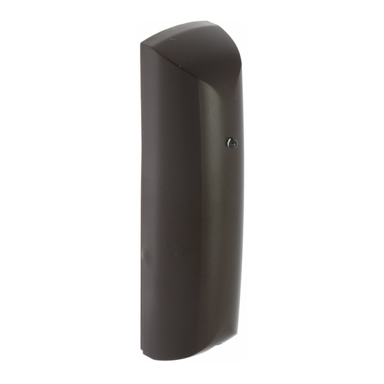
    Introduction Le détecteur radio Spyder 738r est un détecteur de chocs et de vibrations capable de transmettre des informations d’alarme en utilisant la technologie de bande passante étroite 868 MHz propre à Eaton’s Security Business. Il est ainsi en mesure de transmettre des données à...
  • Page 26 Autoprotections Avant et arrière Dimensions 112 x 30 x 27 mm (h x l x p) Poids 46 g (pile incluse) Conformité EN50131-2 Niveau 2 EN61000-6-3:2001 Norme environnementale classe II La figure 1 montre comment se présente l’extérieur du détecteur Spyder. La figure 2 présente quant à...
  • Page 27 1. LED d’activité / d’apprentissage 2. Potentiomètre de réglage de la sensibilité VR1 3. Contact d’autoprotection d’ouverture du boîtier 4. LED Calibrage 5. Pile 6. Contact d’autoprotection à l’arrachage 7. Cavaliers de sélection des modes de fonctionne- ment Fig. 2...
  • Page 28: Equipements Compatibles

    Equipements compatibles 762r Récepteur deux canaux 768r / 769r Récepteur huit canaux 790rEUR-00 Mesureur de champ Homelink 75 Centrale radio domestique Installation Localisation Afin de garantir un fonctionnement correct de l’émetteur radio, NE PAS l’installer : Près du sol. Sur ou à proximité de grandes structures métalliques. A moins d’un mètre de câbles secteur ou de tuyauteries métalliques d’arrivée d’eau ou de gaz.
  • Page 29 par plusieurs détecteurs, il est impératif de s’assurer que ceux-ci ne sont pas espacés de plus de 10 mètres les uns des autres. Dans le cas contraire, toute la surface peut ne pas être incluse dans la surveillance. Fig. 3 Fig.
  • Page 30: Préparation De L'installation

    Préparation de l’installation 1. Retirer la vis du capot puis soulever ce dernier. 2. Extraire le circuit imprimé en le faisant glisser hors de son support de fixation. 3. Installer une pile 3 V CR2 Li/MnO2 (fournie) dans l’emplacement prévu à cet effet sur le circuit imprimé.
  • Page 31: Configuration

    fisamment la barre d’autoprotection se trouvant à l’intérieur du boîtier pour permettre l’activation du contact d’autoprotection. 5. Remettre le circuit imprimé à sa place, dans l’embase du boîtier. Configuration Le détecteur radio Spyder peut prendre plusieurs modes de fonctionnement. La sélection du mode de fonctionnement requis se fait en positionnant les cavaliers comme suit : Cavalier Fonction...
  • Page 32 radio Spyder. Il est à noter que ce détecteur ne peut être placé en mode Calibrage que lorsque le contact d’autoprotection d’ouverture du capot est ouvert (voir le paragraphe “Mise en service du détecteur radio Spyder” ci-dessous.) Mode Discret Maintenir le cavalier D en place pour désactiver le fonctionnement de la LED d’activité.
  • Page 33 Fig. 5 Fig. 6 Fig. 8 Fig. 7...
  • Page 34: Mise En Service Du Détecteur Radio Spyder

    Mise en service du détecteur radio Spyder : 1. Mettre le cavalier C en place afin de faire passer le détecteur radio Spyder en mode calibrage. Remarque : si la tension de la pile est faible, la LED Calibrage clignote en continu. Il est dans ce cas nécessaire de remplacer la pile.
  • Page 35 Maintenance Eaton’s Security Business recommande de renouveler régulièrement la procédure de cali- brage du détecteur radio Spyder (voir le paragraphe Configuration). Remplacer la pile tous les 2 ans ou dès que la centrale signale une condition de tension basse de la pile du détecteur.
  • Page 36 La plus grande attention a été apportée à l’exactitude des informations contenues dans ce document. Les auteurs de cette notice ainsi que la société Eaton’s Security Business déclinent toute responsabilité en cas de pertes ou de dommages provoqués ou supposés avoir été...
  • Page 37: Specifiche Tecniche

    Introduzione Il sensore a vibrazione 738r utilizza la tecnologia radio Eaton’s Security Business a 868MHz, FM e Banda Stretta per trasmettere gli allarmi. Il sensore è compatibile con i ricevitori 762 e 768, espansioni 9960 e la centrale Homelink 75. Il 738r è, infatti, in grado di trasmettere il proprio codice ID via infrarosso emesso dal LED di attività...
  • Page 38 1. LED Attività 2. Vite coperchio 3. Antenna 4. Modulo trasmettitore 5. Batteria Fig. 1...
  • Page 39 1. LED Attività/Apprendimento 2. VR1. Potenziometro per la sensibilità 3. Tamper coperchio 4. LED calibrazione 5. Batteria 6. Tamper posteriore antistrappo 7. Jumper per modo di funzionamento Fig. 2...
  • Page 40: Dispositivi Compatibili

    Dispositivi Compatibili 762r Ricevitore 2 Canali 768r/769r Ricevitore/Espansione 8 Canali 790rEUR-00 Misuratore di segnale Homelink 75 Centrale Radio 9960EUR-08/16 Espansione radio centrali ibride Installazione Posizionamento Per essere certi che il sensore funzioni correttamente, NON installare l’unità: Vicino al pavimento. Vicino o sopra ampie strutture metalliche. A meno di un metro da tubi del gas, condutture dell’acqua o cavi ad alta tensione.
  • Page 41 Fig. 3 Fig. 4 Nota: La copertura mostrata è solo di esem- pio. La sensibilità può variare a seconda della superficie..
  • Page 42: Installazione Fisica

    Preparazione alla Installazione 1. Rimuovere le viti ed aprire il contenitore dal basso. 2. Liberare il circuito stampato dagli appositi sostegni per rimuoverlo. 3. Inserire la batteria in dotazione (3V CR2 Li/MnO2) nell’apposto alloggiamento. Apprendimento 1. Assicurarsi che il ricevitore sia in apprendimento (vedere il manuale di programmazione del ricevitore).
  • Page 43 Configurazione Il sensore 738r Spyder ha differenti modi di funzionamento. Selezionare il modo richiesto posizionando i jumper (ponticelli) come segue: Jumper Funzione Selezione Sensibilità Il jumper A imposta la sensibilità alta o bassa del sensore. Inserire il jumper per impostare la sensibilità BASSA. Rimuovere il jumper per impostare la sensibilità ALTA.
  • Page 44 Fig. 5 Fig. 6 Fig. 8 Fig. 7...
  • Page 45 Per configurare il sensore radio Spyder: 1. Inserire il jumper C per mettere il sensore in modo Calibrazione. Nota: Se la batteria è bassa il LED di Calibrazione lampeggia. Inserire una batteria nuova. 2. Girare il potenziometro VR1 totalmente in senso antiorario. Il sensore è ora con la sen- Girare il potenziometro VR1 totalmente in senso antiorario.
  • Page 46: Sostituzione Della Batteria

    © Eaton’s Security Business 2013 Ogni sforzo è stato compiuto per garantire la correttezza dei contenuti del presente testo. Tuttavia, gli autori e la Eaton’s Security Business non accettano responsabilità per perdite o danni causati o presumibilmente causati dal presente testo direttamente o indiretta-...
  • Page 48 Product Support (UK) Tel: +44 (0)01594 541 978 Available between: 08:30 and 17:00 Monday to Friday, Product Support Fax: (01594) 545401 www.cooper-security.com Cooper Sécurité SAS (Groupe Eaton) PEE II - Rue Beethoven 63204 Riom T : 0 820 867 867 F : 0 820 888 526 www.cooperfrance.com...

Table des Matières