IFM Electronic ASinterface AC5210 Notice De Montage

Manuels Connexes pour IFM Electronic ASinterface AC5210


Sommaire des Matières pour IFM Electronic ASinterface AC5210
-
Page 8: Fonctionnement Et Caractéristiques
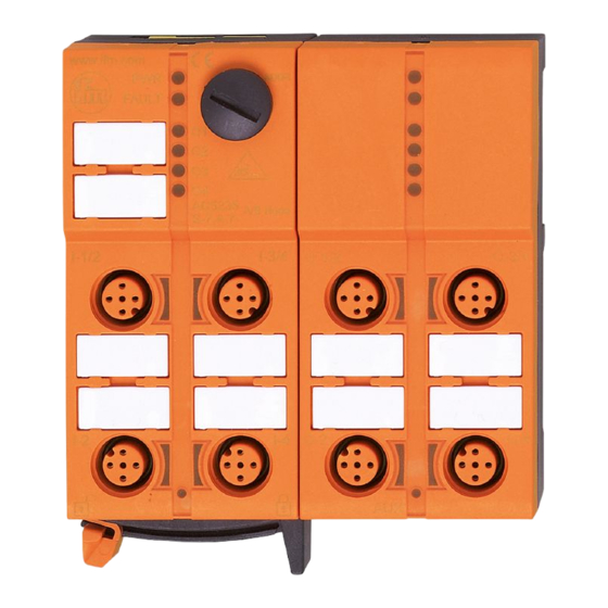
Fonctionnement et caractéristiques • nombre maximal de modules par maître: 31 (2 esclaves A/B indépen- dants par module) • Version AS-interface 3.0, compatibilité descendante Eléments de service et d'indication LED PWR interface d'adressage LED FAULT étiquettes 8 prises M12 Montage Consignes de montage à... - Page 9 Important : Les deux esclaves peuvent être adressés avec toute adresse A/B (par ex. 3A/6A ou 9A/25B, etc.). Aucune adresse ne peut être affectée double- ment (par ex. 3A/3A ou 9B/9B, etc.). Récupérer le réglage en usine (adressage des deux esclaves à 0) A l'aide de l'unité...
-
Page 10: Raccordement Électrique
Raccordement électrique Raccordez les connecteurs des capteurs aux prises M12. Afin de garantir le degré de protection IP 67 vous devrez • couvrir les prises non utilisées avec des bouchons de protection (E73004)*, couple de serrage 0,6...0,8 Nm. • utiliser le joint d'étanchéité pour l'extrémité du câble plat (E70413)* si le module se trouve à... -
Page 11: Montage / Assembly
Montage / Assembly Flachkabelausrichtung Auslieferungszustand Legen Sie das gelbe Flachkabel sorgfältig in die Profilnut ein. Orientation of the flat cable on delivery Carefully place the yellow flat cable into the profile slot. Orientation du câble plat à la livraison Posez le câble plat jaune soigneu- sement dans le guide profilé. - Page 12 Verriegeln Sie das Gerät. Lock the unit. Verrouillez l'appareil. mitgelieferte Unterteil ermöglicht die Ausrichtung des Flachkabels in drei Richtungen. Legen Sie die Flachkabelführung (1) für die gewünschte Richtung entsprechend ein. With the supplied lower part the flat cable can be aligned in three directions.
- Page 13 Einstellungen am Unterteil Wählen gemäß Ihrer gewünschten Flachkabelausrich- tung (→) die Position 1, 2 oder 3 aus. A = Auslieferungszustand Settings at the lower part Select the position 1, 2 or 3 depending on the requested flat cable alignment (→). A = Factory setting Réglages sur l'embase Sélectionnez la position 1, 2 ou 3...
- Page 14 Einstellungen am Oberteil Stellen Sie dann am Oberteil die gewählte Position ein, drehen Sie dafür das Dreieck auf die ent- sprechende Ziffer (Bild D1 und D2). Settings at the upper part Then set the selected position at the upper part. To do so, turn the arrow to the corresponding num- ber (figure D1 and D2).
- Page 15 Gerät öffnen / Open the unit / Ouvrir l'appareil Öffnen Sie das Gerät wie abge- bildet mit einem Werkzeug (z. B. Schraubendreher). Open the unit using a tool as shown (e.g. screwdriver). Ouvrez l'appareil à l'aide d'un outil comme indiqué (par ex. tournevis).