Table des Matières
Publicité
Les langues disponibles
Les langues disponibles
Liens rapides
Publicité
Chapitres
Table des Matières

Manuels Connexes pour Ecolab MFV III-IV

Sommaire des Matières pour Ecolab MFV III-IV
- Page 1 Betriebsanleitung Operating Instructions Manuel d‘utilisation Mehrfunktionsventil Multiple Function Valve Soupape multifonction MFV III-IV (120 - 750 l/h) Deutsch English Français MFV III-IV 417101434 Rev. 5-05.2019 20.05.2019...
- Page 3 Betriebsanleitung Mehrfunktionsventil MFV III-IV (120 - 750 l/h) MFV III-IV 417101434 Rev. 5-05.2019 20.05.2019 DEUTSCH...
-
Page 4: Table Des Matières
Inhaltsverzeichnis Inhaltsverzeichnis Allgemeines......................4 1.1 Betriebsanleitungen mit Smartphones aufrufen..........5 1.1.1 Installation der „Ecolab DocuApp“ für Android..........5 1.1.2 Installation der „DocuApp“ für IOS (Apple)........... 5 1.2 Urheberschutz....................6 1.3 Symbole, Hervorhebungen und Aufzählungen........... 6 1.4 Artikelnummern / EBS Artikelnummern.............. 7 1.5 Transport, Verpackung und Lagerung.............. - Page 5 Inhaltsverzeichnis Wartung........................33 9.1 Austausch der Membrane................. 34 9.2 Austausch des Überström-Kugelventils............35 Ersatz- und Verschleißteile / Zubehör..............36 10.1 Ersatz- und Verschleißteile................36 10.2 Zubehör......................37 10.2.1 Anschluss an Schlauchleitung mit Klemmringverschraubung..... 37 10.2.2 Anschluss an Druckschlauchtülle mit Schlauchschelle....... 38 10.2.3 Anschluss an Rohrleitungen................
-
Page 6: Allgemeines
Reparaturarbeiten müssen die einschlägigen Kapitel der Betriebsanleitung gelesen, verstanden und beachtet werden. Die jeweils aktuellste und komplette Betriebsanleitung wird im Internet zur Verfügung gestellt: https://www.ecolab-engineering.de/fileadmin/download/bedienungsanleitungen/ dosiertechnik/Zubeh-r/417101434_MFV_EMPIII-IV.pdf Wenn Sie die Betriebsanleitung mit einem Tablet oder Smartphone downloaden möchten, können Sie den aufgeführten QR-Code nutzen. -
Page 7: Betriebsanleitungen Mit Smartphones Aufrufen
Rufen sie den "Google Play Store" mit Ihrem Smartphone /Tablet auf. Geben Sie den Namen „Ecolab DocuAPP“ im Suchfeld ein. Wählen Sie anhand des Suchbegriffes Ecolab DocuAPP in Verbindung mit diesem Symbol die „Ecolab DocuApp“ aus. Betätigen Sie den Button [installieren]. -
Page 8: Urheberschutz
Die Überlassung dieser Anleitung an Dritte, Vervielfältigungen in jeglicher Art und Form, auch auszugsweise, sowie die Verwertung und/oder Mitteilung des Inhaltes sind ohne schriftliche Genehmigung von Ecolab Engineering (im folgenden "Hersteller”) außer für interne Zwecke nicht gestattet. Zuwiderhandlungen verpflichten zu Schadenersatz. -
Page 9: Artikelnummern / Ebs Artikelnummern
Bedienelemente (z. B. Taster, Schalter), Anzeigeelemente (z. B. Signalleuchten) „Anzeige“ Bildschirmelemente (z. B. Schaltflächen, Belegung von Funktionstasten) Artikelnummern / EBS Artikelnummern Innerhalb dieser Betriebsanleitung können sowohl Artikelnummern, als auch EBS-Artikelnummern dargestellt sein. EBS-Artikelnummern sind Ecolab interne Artikelnummern und werden ausschließlich „konzernintern“ verwendet. 417101434 Rev. 5-05.2019... -
Page 10: Transport, Verpackung Und Lagerung
Allgemeines Transport, Verpackung und Lagerung 1.5.1 Transport Das Gerät wird in einem Karton verpackt geliefert. Die Abmessungen der Verpackung und das Verpackungsgewicht entnehmen Sie bitte den Technischen Daten. Unsachgemäßer Transport HINWEIS! Sachschäden durch unsachgemäßen Transport! Bei unsachgemäßem Transport können Transportstücke fallen oder umstürzen. -
Page 11: Verpackung
Allgemeines 1.5.2 Verpackung Die einzelnen Packstücke sind entsprechend den zu erwartenden Transportbedingungen verpackt. Für die Verpackung wurden ausschließlich umweltfreundliche Materialien verwendet. Die Verpackung soll die einzelnen Bauteile bis zur Montage vor Transportschäden, Korrosion und anderen Beschädigungen schützen. Daher die Verpackung nicht zerstören und erst kurz vor der Montage entfernen. UMWELT! Gefahr für die Umwelt durch falsche Entsorgung! Verpackungsmaterialien sind wertvolle Rohstoffe und können in vielen... -
Page 12: Lagerung
Allgemeines 1.5.3 Lagerung Unter Umständen befinden sich auf den Packstücken Hinweise zur Lagerung, die über die hier genannten Anforderungen hinausgehen. Diese sind entsprechend einzuhalten. Folgende Lagerbdingungen sind zu beachten: Nicht im Freien aufbewahren. Trocken und staubfrei lagern. Keinen aggressiven Medien aussetzen. Vor Sonneneinstrahlung schützen. -
Page 13: Service- Und Kontaktadresse Zum Hersteller
Allgemeines Service- und Kontaktadresse zum Hersteller Ecolab Engineering GmbH Raiffeisenstraße 7 D-83313 Siegsdorf Telefon (+49) 86 62 / 61 0 Telefax (+49) 86 62 / 61 166 Email: engineering-mailbox@ecolab.com http://www.ecolab-engineering.com 417101434 Rev. 5-05.2019... -
Page 14: Sicherheit
Sicherheit Sicherheit Allgemeine Sicherheitshinweise GEFAHR! Wenn anzunehmen ist, dass ein gefahrloser Betrieb nicht mehr möglich ist, so ist das Gerät unverzüglich außer Betrieb zu setzen und gegen unabsichtlichen Betrieb zu sichern. Das ist der Fall: – wenn das Gerät sichtbare Beschädigungen aufweist, –... -
Page 15: Eigenmächtiger Umbau Und Ersatzteilherstellung
Sicherheit 2.2.1 Eigenmächtiger Umbau und Ersatzteilherstellung VORSICHT! Eigenmächtige Umbauten oder Veränderungen sind nur nach Absprache und mit Genehmigung des Herstellers zulässig. Originalersatzteile und vom Hersteller autorisiertes Zubehör dienen der Sicherheit. Die Verwendung anderer Teile schließt die Haftung für die daraus entstehenden Folgen aus. -
Page 16: Personalanforderungen
Sicherheit Der Betreiber muss die örtlichen gesetzlichen Bestimmungen für: die Sicherheit des Personals (BG- und Unfallverhütungsvorschriften, Arbeitsstätten- Richtlinien), z.B. Betriebsanweisungen, auch nach §20 GefStoffV, persönliche Schutzausrüstung (PSA), Vorsorgeuntersuchungen; die Sicherheit der Arbeitsmittel (Schutzausrüstung, Arbeitsanweisungen, Verfahrensrisiken und Wartung); die Produktbeschaffung (Sicherheitsdatenblätter, Gefahrstoffverzeichnis); die Produktentsorgung (Abfallgesetz);... - Page 17 Sicherheit Bediener Der Bediener wurde in einer Unterweisung durch den Betreiber über die ihm übertragenen Aufgaben und möglichen Gefahren bei unsachgemäßem Verhalten unterrichtet. Aufgaben, die über die Bedienung im Normalbetrieb hinausgehen, darf der Bediener nur ausführen, wenn dies in dieser Anleitung angegeben ist und der Betreiber ihn ausdrücklich damit betraut hat.
-
Page 18: Persönliche Schutzausrüstung (Psa)
Sicherheit Unbefugte Personen GEFAHR! Unbefugte Personen, welche die hier beschriebenen Anforderungen nicht erfüllen, kennen die Gefahren im Arbeitsbereich nicht. Daher besteht für Unbefugte die Gefahr von Verletzungen. Umgang mit unbefugten Personen: – Arbeiten unterbrechen, solange sich Unbefugte im Gefahren- und Arbeitsbereich aufhalten. -
Page 19: Hinweise Auf Gefährdungen
Sicherheit WARNUNG! Schutzhandschuhe, chemikalienbeständig Bei Arbeiten in Bereichen, die mit nebenstehendem Symbol gekennzeichnet sind, sind entsprechende Schutzhandschuhe zu tragen. Chemikalienbeständige Schutzhandschuhe dienen dem Schutz der Hände vor aggressiven Chemikalien. WARNUNG! Schutzhandschuhe, mechanische Gefährdung Bei Arbeiten in Bereichen, die mit nebenstehendem Symbol gekennzeichnet sind, sind entsprechende Schutzhandschuhe zu tragen. -
Page 20: Allgemeine Gefahren Am Arbeitsplatz
Sicherheit Unbefugter Zutritt GEFAHR! Unbefugter Zutritt Der Betreiber hat sicherzustellen, dass das Betreten des Bedienbereiches durch unbefugte Personen verhindert wird. 2.10 Allgemeine Gefahren am Arbeitsplatz Rutschgefahr GEFAHR! Rutschgefahren sind mit nebenstehendem Symbol gekennzeichnet. Verschüttete Chemikalien erzeugen bei Nässe Rutschgefahr. WARNUNG! Rutschgefahr durch austretende Flüssigkeit im Arbeits- und Bereitstellungsbereich! –... -
Page 21: Installations-, Wartungs- Und Reparaturarbeiten
Sicherheit UMWELT! Ausgelaufenes, verschüttetes Dosiermedium kann die Umwelt schädigen. Ausgelaufenes, verschüttetes Dosiermedium nach Anweisungen des Sicherheitsdatenblattes fachgerecht aufnehmen und entsorgen. Unbedingt auf die Verwendung der vorgeschrieben PSA achten. Vorbeugende Maßnahme: – Produktbehälter in eine Wanne stellen, um ausgetretene Flüssigkeiten umweltgerecht aufzufangen. 2.11 Installations-, Wartungs- und Reparaturarbeiten HINWEIS! -
Page 22: Sicherheitsdatenblätter
Sicherheit am Arbeitsplatz treffen kann. Sollten Sie nicht sicher sein, ein aktuelles Sicherheitsdatenblatt vorliegen zu haben, wenden Sie sich bitte an Ihren Ecolab Fachberater. Er wird Ihnen gerne weiterhelfen, damit die Maßnahmen zum ständigen Schutz der Gesundheit am Arbeitsplatz gewährleistet sind. -
Page 23: Lieferumfang
Lieferumfang Lieferumfang Darstellung Beschreibung Artikel-Nr. MFV PVEP10 G1¼ -G1¼ -99 250065 MFV PVFP10 G1¼ -G1¼ -99 250064 MFV PPEP10 G1¼ -G1¼ -99 250061 MFV PPFP10 G1¼ -G1¼ -99 250060 MFV PVEP10 G2-G2-99 250067 MFV PVFP10 G2-G2-99 250066 MFV PPEP10 G2-G2-99 250063 MFV PPFP10 G2-G2-99 250062... -
Page 24: Funktionsbeschreibung
Funktionsbeschreibung Funktionsbeschreibung Das Mehrfunktionsventil vereint die Funktionen: Überströmen Druckhalten Entlüften Entleeren Dieses Sicherheitsbauteil dient dem Schutz des Rohrleitungssystems und der Dosierpumpe und ermöglicht eine zuverlässige Inbetriebnahme und Wartung der Anlage. Im Normalbetrieb arbeitet die Dosierpumpe gegen den am Mehrfunktionsventil eingestellten Gegendruck. Erhöht sich der Gegendruck in der Dosierleitung über den am Mehrfunktionsventil eingestellten Überdruck, wird dieser über die Bypassleitung entlastet. -
Page 25: Aufbau
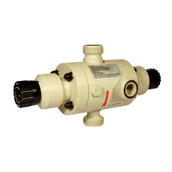
Aufbau Aufbau Abb. 1: Aufbau Ventileingang (von Dosierpumpe) Druckhalteseite: Entleerung (Einstellknopf “A“), Abb. 8 Ventilausgang (zur Dosierleitung) Manometeranschluss, G ¼“ (im Auslieferzustand durch Bypassanschluss (zum Behälter) Stopfen verschlossen) Überdruck: Entlüftung / Entleerung (Einstellknopf “B“), Abb. 7 Die O-Ringe der Anschlüsse für: Eingang (Pos. 1), Ausgang (Pos. 2) und Bypass (Pos. -
Page 26: Montage, Installation
Montage, Installation Montage, Installation Personal: Mechaniker Servicepersonal Fachkraft Abb. 2: Montage, Mounting, Assemblage Im Lieferumfang enthaltene Schellen gemäß Zeichnung anbringen. MFV in die Schellen einrasten und Sicherungsbügel der Schelle schließen. WARNUNG! Die Installation ist durch zugelassene Fachkräfte durchzuführen, die allgemeinen Richtlinien und örtlichen Installationsvorschriften sind zu beachten! 417101434 Rev. -
Page 27: Einbauschema
Montage, Installation Einbauschema Abb. 3: Einbauschema Geräteinstallation Personal: Mechaniker Servicepersonal Fachkraft Die hier beschriebenen Arbeitschritte gelten für alle Anschlüsse (Eingang, Ausgang und Bypass) gleichermaßen. Ä Kapitel 5 „Aufbau“ auf Seite 23), ( Ä auf Seite 23 Pos. 1, 2, 3). VORSICHT! Da das MFV kein absolut dicht schließendes Absperrorgan ist, muss die Bypassleitung (Entlüftungsleitung) immer angeschlossen und zurück in den... -
Page 28: Schlauchanschluss
Montage, Installation 6.2.1 Schlauchanschluss Abb. 4: Schlauchanschluss Schlauch (Pos. 1) gerade abschneiden. O-Ring (Pos. 5) in Nut der Anschlüsse einlegen. Schlauchtülle (Pos. 4; mit Einlegeteil verschweißt) mit Überwurfmutter (Pos. 3) festziehen. Schlauchklemme (Pos. 2); 2 Stück empfohlen; über Schlauch schieben. Schlauch über Schlauchtülle (Pos. -
Page 29: Rohranschluss
Montage, Installation 6.2.2 Rohranschluss Bei starrer Verrohrung der Dosierleitung muss ein Pulsationsdämpfer zur Vermeidung von Druckschlägen installiert werden. Abb. 5: Rohranschluss Rohr (Pos. 1) gerade abtrennen und entgraten. Überwurfmutter (Pos. 2) über Rohr schieben. Rohr mit Einlegeteil (Pos. 3) verschweißen bzw. verkleben (PVC). O-Ring (Pos. -
Page 30: Inbetriebnahme / Betrieb
Inbetriebnahme / Betrieb Inbetriebnahme / Betrieb Personal: Mechaniker Servicepersonal Fachkraft WARNUNG! Besondere Vorsicht ist im Umgang mit chemischen Dosiermedien geboten! Beachten Sie unbedingt das Produktdatenblatt des Dosiermediums, um Verletzungen jeglicher Art zu verhindern! Überprüfen Sie vor Inbetriebnahme die Chemische Beständigkeit der Ventilwerkstoffe gegenüber dem Dosiermedium. -
Page 31: Einstellung Überströmfunktion (Überdruck)
Inbetriebnahme / Betrieb Einstellung Überströmfunktion (Überdruck) Die Überströmfunktion ist eine Sicherheitsfunktion, um eine unzulässige Erhöhung des Gegendruckes in der Dosierleitung zu verhindern. Bei Überschreiten des voreingestellten Überdruckes öffnet das Ventil und das Produkt strömt durch die Bypassleitung zurück in den Produktbehälter. Für eine korrekte Einstellung muss sich der Drehknopf B auf Ä... -
Page 32: Einstellung Druckhaltefunktion (Gegendruck)
Inbetriebnahme / Betrieb Einstellung Druckhaltefunktion (Gegendruck) Die Druckhaltefunktion erzeugt einen Gegendruck der ein Leerhebern des Produktbehälters verhindert. die Dosiergenauigkeit bei freiem Auslauf erhöht. ein unerwünschtes Entleeren der Dosierleitung verhindert. Für eine korrekte Einstellung muss sich der Drehknopf A auf Position “Rechtsanschlag“ befinden. ( Ä... -
Page 33: Normalbetrieb
Inbetriebnahme / Betrieb Normalbetrieb Abb. 9: Normalbetrieb Im Normalbetrieb arbeitet das MFV mit eingestellter Druckhalte- und Überdruckfunktion. Drehknöpfe A + B sind geschlossen (Rechtsanschlag). Ventilgehäuseschrauben (Abb. 11, Pos. 1) nach 24 Stunden nachziehen. Anzugsmoment: 8 Nm. Entleerung Abb. 10: Normalbetrieb In der Entleerungsstellung wird der Dosiergegendruck entlastet, das Produkt aus der Dosierleitung kann durch die Bypassleitung in den Produktbehälter zurückfließen. -
Page 34: Fehlerbehebung
Fehlerbehebung Fehlerbehebung Fehlerbeschreibung Ursache Abhilfe Bei laufender Dosierpumpe tritt Drehknopf Drehknopf schließen permanent Dosiermedium aus der Überströmfunktion offen (Drehung nach rechts) Rücklaufleitung (Anschluss Bypass) Systemdruck zu hoch Systemdruck prüfen und ggf. Überdruckeinstellung erhöhen Überdruck zu gering Überdruckeinstellung eingestellt erhöhen Dichtsitz der Kugel Zerlegen und Reinigen verschmutzt Druckfeder... -
Page 35: Wartung
Wartung Wartung Personal: Mechaniker Servicepersonal VORSICHT! Die Wartung darf nur von sachkundigen und autorisierten Personen durchgeführt werden. Intervall Wartungsarbeit 1/4 jährlich Kontrolle von Saug-, Druck und Rücklaufleitung auf leckfreien Anschluss. Kontrolle der Gehäuseschrauben auf festen Sitz, ggf. mit 8 Nm nachziehen. Kontrolle der Überströmfunktion (Überdruck). -
Page 36: Austausch Der Membrane
Wartung Austausch der Membrane Abb. 11: Abmessungen Ventilgehäuseschraube Membrane (Druckhalteseite) Ventilkopf (Überdruckseite) Ventilkopf (Druckhalteseite) Membrane (Überdruckseite) Muttern, M 6 Überström-Kugelventil Abdeckkappen von den Ventilgehäuseschrauben (Pos. 1) und Muttern (Pos. 6 und 7) abziehen. Muttern (Pos. 6 und 7) mit Schraubenschlüssel, Größe SW10, lösen und entfernen. Ventilkopf (Pos. -
Page 37: Austausch Des Überström-Kugelventils
Wartung Austausch des Überström-Kugelventils Abb. 12: Austausch des Überström-Kugelventils Ventilkäfig Kugel Kugelsitz-O-Ring Haltering O-Ring Ä Kapitel 9 „Wartung“ auf Seite 33 beschrieben zerlegen. MFV wie unter Kugel (4) entfernen (MFV umdrehen, Kugel rollt raus). Ventilkäfig (1) abziehen. Haltering (5) mit den O-Ringen (2 und 3) entnehmen. O-Ring (3) mit geeignetem Gleitmittel benetzen und in den Sitz des MFV einlegen. -
Page 38: Ersatz- Und Verschleißteile / Zubehör
Ersatz- und Verschleißteile / Zubehör Ersatz- und Verschleißteile / Zubehör 10.1 Ersatz- und Verschleißteile Abb. 13: Ersatzteile Pos. Bezeichnung Artikel-Nr. O-Ring 22x2 75 FPM 602 in Ventil (250060, 250062, 250064, 250066) 417003312 O-Ring 22x2 70 EPDM 281 in Ventil (250061, 250063, 250065, 250067) 417001217 O-Ring 16x3 75 FPM 602 in Ventil (250060, 250062, 250064, 250066) 417003346... -
Page 39: Ersatz- Und Verschleißteile / Zubehör
Ersatz- und Verschleißteile / Zubehör 10.2 Zubehör 10.2.1 Anschluss an Schlauchleitung mit Klemmringverschraubung Darstellung Artikel / Bezeichnung Artikel-Nr. 1 ¼“ Artikel-Nr. 2“ O-Ring Viton B 417003593 417003412 EPDM 417001277 417001943 Kegelteil für PVC-Gewebeschlauch 12/21 (ID/AD) 34900242 PVDF 38610410 VA (1.4571) 38610201 Spannteil für PVC-Gewebeschlauch 12/21 (ID/AD) 34900243... -
Page 40: Anschluss An Druckschlauchtülle Mit Schlauchschelle
Ersatz- und Verschleißteile / Zubehör 10.2.2 Anschluss an Druckschlauchtülle mit Schlauchschelle Darstellung Artikel / Bezeichnung Artikel-Nr. 1 ¼“ Artikel-Nr. 2“ Druckschlauchtülle PP für Schlauch NW 20/22 250031 34950253 PP für Schlauch NW 25/27 250033 34950254 PP für Schlauch NW 32 34950255 PVDF für Schlauch NW 20/22 34950199... -
Page 41: Anschluss An Rohrleitungen
Ersatz- und Verschleißteile / Zubehör 10.2.3 Anschluss an Rohrleitungen Darstellung Artikel / Bezeichnung Artikel-Nr. 1 ¼“ Artikel-Nr. 2“ Einlegteil (Schweißmuffe) DN 20 (d25) 415099709 PVDF 415099033 VA für Einschraubgewinde G ¾ 38610407 Einlegteil (Schweißmuffe) DN 25 (d32) 34950191 PVDF 34950192 Einlegteil (Schweißmuffe) DN 32 (d40) 415099711 PVDF... -
Page 42: Technische Daten
Technische Daten Technische Daten Ventilgröße G 1¼“ Angabe Wert Einheit Überdruckfunktion (Werkseinstellung 0,3 (3)) 0,1-1 (1-10) MPa (bar) Druckhaltefunktion (Werkseinstellung 0,05 (0,5)) 0,05-0,3 (0,5-3) MPa (bar) Durchfluss max. l/h 210 l/h Max. Viskosität 400 MPa Ventilgröße G 2“ Angabe Wert Einheit Überdruckfunktion (Werkseinstellung 0,3 (3)) 0,1-1 (1-10) MPa (bar) Druckhaltefunktion (Werkseinstellung 0,05 (0,5)) -
Page 43: Mehrfunktionsventile - Schlüssel
Technische Daten 11.2 Mehrfunktionsventile - Schlüssel Beispielschlüssel: MFV PV FP GL 10 G2 G2 99 Bestandteile des Pumpenschlüssels "Bedienteil": Pos. 1: „Ventilbezeichnung“ Mehrfunktionsventil Pos. 2: „Werkstoff Gehäuse“ PVDF Pos. 3: „Werkstoff Dichtungen“ Viton B EPDM Pos. 4: „ Werkstoff Kugel“ Glas Pos. -
Page 44: Öffnungsdrücke
Technische Daten 11.4 Öffnungsdrücke Angabe Wert Einheit Druckhaltefunktion (Gegendruck), 0,05-0,3 (0,5-3) MPa (bar) Öffnungsdruck (Werkseinstellung) Überströmfunktion (Überdruck), 0,3-1,0 (3-8) MPa (bar) Öffnungsdruck (Werkseinstellung) Öffnungsdruck 12 bar (1,2 MPa) bei Einsatz bis Durchfluss (Q)=140 l/h zulässig! 11.5 Abmessungen Abb. 14: Abmessungen Anschlussgewinde (a) Artikel-Nr. -
Page 45: Außerbetrieb Setzen / Demontage / Umweltschutz
Außerbetrieb setzen / Demontage / Umweltschutz Außerbetrieb setzen / Demontage / Umweltschutz Personal: Bediener Mechaniker Servicepersonal Fachkraft GEFAHR! Verletzungsgefahr durch außer Acht lassen der vorgeschriebenen Schutzausrüstung (PSA)! Beachten Sie bei allen Demontagearbeiten die Verwendung der laut Produktdatenblatt vorgeschriebenen PSA. 12.1 Außer Betrieb setzen GEFAHR! Die hier beschrieben Vorgänge dürfen nur von Fachpersonal, wie am... -
Page 46: Entsorgung Und Umweltschutz
Außerbetrieb setzen / Demontage / Umweltschutz HINWEIS! Sachschäden durch Verwendung von falschem Werkzeug! Durch Verwendung von falschem Werkzeug bei Montage, Wartung oder Störungsbeseitigung können Sachschäden entstehen. Nur bestimmungsgemäßes Werkzeug verwenden. Zur Demontage wie folgt vorgehen: Vor Beginn aller Arbeiten für ausreichenden Platz sorgen. Betriebs- und Hilfsstoffe sowie restliche Verarbeitungsmaterialien entfernen und umweltgerecht entsorgen. - Page 47 Außerbetrieb setzen / Demontage / Umweltschutz UMWELT! Reduzierung, bzw. Vermeidung des Abfalls aus wiederverwendbaren Rohstoffen Entsorgen Sie keine Bauteile im Hausmüll, sondern führen Sie diese den entsprechenden Sammelstellen zur Wiederverwertung zu. Wir möchten auf die Einhaltung der Richtlinie Elektro- und Elektronik Altgeräte mit der Nummer 2012/19/EU hinweisen, dessen Ziel und Zweck die Reduzierung, bzw.
-
Page 48: Einbauerklärung
Einbauerklärung Einbauerklärung 417101434 Rev. 5-05.2019... - Page 50 Operating instructions Multiple Function Valve MFV III-IV (120 - 750 l/h) MFV III-IV 417101434 Rev. 5-05.2019 20.05.2019 ENGLISH...
- Page 51 Table of contents General........................4 1.1 Call up operating instructions with smartphone..........5 1.1.1 Installation of the ‘Ecolab DocuApp’ for Android.......... 5 1.1.2 Installation of the ‘DocuApp’ for IOS (Apple)..........5 1.2 Copyright......................6 1.3 Symbols, highlighting and enumerations............6 1.4 Article numbers / EBS-Article numbers..............
- Page 52 Table of contents Maintenance......................32 9.1 Diaphragm replacement................... 33 9.2 Replacement of the overflow ball valve............34 Spare parts and wear parts / Accessories............35 10.1 Spare parts and wear parts................35 10.2 Accessories....................36 10.2.1 Hose-line connection, with clamping-ring gland.......... 36 10.2.2 Connection for pressure-hose nozzle with hose clip........
-
Page 53: General
The most current and complete operating instructions are made available on the Internet: https://www.ecolab-engineering.de/fileadmin/download/bedienungsanleitungen/ dosiertechnik/Zubeh-r/417101434_MFV_EMPIII-IV.pdf If you want to download the manual with a tablet or smartphone, you can use the QR code listed below. -
Page 54: Call Up Operating Instructions With Smartphone
Call the "Google Play Store" with your smartphone/tablet. Enter the name „Ecolab DocuAPP“ in the search field. Select by the search term Ecolab DocuAPP in conjunction with this symbol ‘Ecolab DocuApp’ . Press the button [install]. ð The ‘Ecolab DocuApp’... -
Page 55: Copyright
This manual is copyright protected. Transferring this manual to third parties, reproduction in any form – even partially – and the exploitation and/or disclosure of the contents without written permission from Ecolab Engineering (hereinafter “the manufacturer”) is prohibited except for internal purposes. -
Page 56: Article Numbers / Ebs-Article Numbers
Screen elements (e.g. buttons, assignment of function keys) Article numbers / EBS-Article numbers Both item numbers and EBS numbers could be shown in these operating instructions. EBS numbers are Ecolab-internal item numbers and are used exclusively “internal within the group”. 417101434 Rev. 5-05.2019... -
Page 57: Shipping, Packaging And Storage
General Shipping, packaging and storage 1.5.1 Shipping The unit is delivered in suitably adapted packaging. For the dimensions of the packaging and packing weight please refer to the "Technical Data" chapter . Improper transport NOTICE! Material damage due to improper transportation! Transport units can fall or tip over if improperly transported. - Page 58 General 1.5.2 Packaging The individual packages are packaged to reflect the expected transport conditions. Only environmentally-friendly materials were used for the packaging. The packaging is designed to protect the individual components up to assembly against shipping damage, corrosion and other damage. Therefore, do not destroy the packaging and only remove it just before assembly.
-
Page 59: Storage
General 1.5.3 Storage Under certain circumstances, instructions for storage, which go beyond the requirements listed here, can be found on the package. Comply with these. Store packages under the following conditions: Do not store outdoors. Store in a dry and dust-free place. Do not expose to aggressive media. -
Page 60: Manufacturer's Service And Contact Address
General Manufacturer's service and contact address Ecolab Engineering GmbH Raiffeisenstraße 7 D-83313 Siegsdorf, Germany Telephone (+49) 86 62 / 61 0 Fax (+49) 86 62 / 61 166 Email: engineering-mailbox@ecolab.com http://www.ecolab-engineering.com 417101434 Rev. 5-05.2019... -
Page 61: Safety
Safety Safety General safety advice DANGER! If you believe that the unit can no longer be operated safely, you must decommission it immediately and secure it so that it cannot be used inadvertently. This applies: – if the unit shown visible signs of damage; –... -
Page 62: Unauthorized Alterations And Production Of Spare Parts
Safety 2.2.1 Unauthorized alterations and production of spare parts CAUTION! Unauthorized conversions or modifications are only allowed by prior permission and requires the approval of the producer. Original spare parts and accessories authorized by the producer serve to enhance safety. The use of other parts excludes liability for the resulting consequences. -
Page 63: Obligations Of The Operator
Safety Obligations of the operator In the EEA (European Economic Area), national implementation of the Directive (89/391/EEC) and corresponding individual directives, in particular the Directive (2009/104/EC) concerning the minimum safety and health requirements for the use of work equipment by workers at work, as amended, are to be observed and adhered to. - Page 64 Safety Manufacturer Certain work may only be carried out by specialist staff of the manufacturer or by staff authorised or specially trained by the manufacturer. Other people or personnel are not authorised to carry out this work. To carry out the work required, please contact our customer service. Operator The operator has been instructed by the owner on the tasks entrusted to it and is aware of the potential dangers associated with incorrect behaviour.
-
Page 65: Personal Protective Equipment (Ppe)
Safety Unauthorised personnel DANGER! Unauthorised persons who do not meet the requirements described here are not familiar with the risks in the operating area. Therefore unauthorised persons are at risk of injury. Working with unauthorised persons: – All work must be suspended for as long as unauthorised persons are present in hazardous or working areas. -
Page 66: Environmental Protection Measures
Safety WARNING! Chemical resistant protective gloves Suitable protective gloves must be worn when working in areas marked with the symbol opposite. Chemical resistant safety gloves protect the hands from aggressive chemicals. WARNING! Protective gloves, mechanical hazards In the event of works in areas, which are identified with an adjacent symbol, appropriate protective gloves are to be worn. -
Page 67: General Workplace Dangers
Safety 2.10 General workplace dangers Risk of slipping DANGER! Slipping hazards are marked by the symbol opposite. Spilled chemicals create a risk of slipping when wet. WARNING! Risk of slipping due to fluid in the operation and provisioning area! – Wear non-slip, chemically resistant shoes when working. –... -
Page 68: Installation, Maintenance And Repairs
If you are not sure as to whether you possess the current safety data sheet, please do not hesitate to contact your Ecolab technical adviser. He will be happy to help you so that the measures for a permanent health protection at the workplace are ensured. -
Page 69: Scope Of Supply
Scope of supply Scope of supply View Description Article-No. Multiple-function valve with G 1¼ "a connecting threads: MFV PVEP10 G1¼ -G1¼ -99 250060 250061 MFV PVFP10 G1¼ -G1¼ -99 250064 MFV PPEP10 G1¼ -G1¼ -99 250065 MFV PPFP10 G1¼ -G1¼ -99 Multiple-function valve with G 2 "a connecting threads: MFV PVEP10 G2-G2-99 250062... -
Page 70: Description Of Function
Description of function Description of function The multiple function valve combines all of the following functions: Overflow Pressure maintenance Venting Drainage This safety-relevant component serves the purpose of protecting the piping system and the metering pump and permits safe and reliable commissioning and maintenance of the system. -
Page 71: Structure
Structure Structure Fig. 1: Structure Valve inlet (from metering pump) Pressure maintenance side: Discharge (Adjustment Valve outlet (to metering line) Knob "A"), Ä on page 29 Bypass connection (to tank) Pressure-gauge connection, G ¼" (blanked off with a Overpressure: Venting / drainage (Adjustment Knob plug in as-delivered condition) "B"), Ä... -
Page 72: Mounting, Installation
Mounting, installation Mounting, installation Personnel: Mechanic Service personnel Specialist Fig. 2: Montage, Mounting, Assemblage Attach the clamps included in the scope of delivery according to the drawing. Engage the MFV in the clamps and close the safety clip of the clamp. WARNING! The installation must be carried out by authorised specialists, the general guidelines and local installation regulations must be observed! -
Page 73: Installation Diagram
Mounting, installation Installation diagram Fig. 3: Installation diagram Device installation Personnel: Mechanic Service personnel Specialist The steps described here apply to all connections (input, output and bypass) equally. Ä Chapter 5 ‘Structure’ on page 22), ( Ä on page 22 Pos. 1, 2, 3). CAUTION! Since the MFV is not an absolutely tight shut-off device, the bypass line (vent line) must always be connected and led back into the dosing medium... -
Page 74: Hose Connection
Mounting, installation 6.2.1 Hose connection Fig. 4: Hose connection Cut the hose (Item 1) straight. Position the O-ring seal (Item 5) in the groove of the connections. Tighten the hose nozzle (Item 4, welded to the insertion element) with the union nut (Item 3). -
Page 75: Pipe Connection
Mounting, installation 6.2.2 Pipe connection A surge damper must be installed for avoidance of pressure surges if the metering line is installed in the form of a rigid pipe. Fig. 5: Pipe connection Cut the pipe (Item 1) off straight and deburr. Slip the union nut (Item 2) over the pipe. -
Page 76: Commissioning / Operation
Commissioning / Operation Commissioning / Operation Personnel: Mechanic Service personnel Specialist WARNING! Special care is necessary in the use and handling of chemical metered fluids! Please adhere under all circumstances to the product data-sheet for the metered fluid, in order to avoid corrosive injuries of all types! Before commissioning, check the chemical resistance of the valve materials to the metered fluid. -
Page 77: Setting Of The Overflow Function (Overpressure)
Commissioning / Operation Setting of the overflow function (overpressure) The overflow function is a safety function intended to prevent any impermissible increase in the counterpressure in the metering line. The valve opens and the product flows via the bypass line back to the product tank if the preset overpressure is exceeded. -
Page 78: Setting Of Pressure-Maintenance Function (Counterpressure)
Commissioning / Operation Setting of pressure-maintenance function (Counterpressure) The pressure-maintenance function generates a counterpressure which: prevents siphoning empty of the product tank enhances metering accuracy with a free outlet prevents undesired emptying of the metering line Rotary Knob A must be in the "Right-hand stop" position to permit correct setting. -
Page 79: Normal Operation
Commissioning / Operation Normal operation Fig. 9: Normal operation During normal operation, the MFV operates with its set pressure maintenance and overpressure function. Rotary Knobs A + B are closed (Right-hand stop). Valve-housing screws (Fig. 11, Item 1) must be retightened after 24 h. Tightening torque: 8 Nm. -
Page 80: Trouble-Shooting
Trouble-shooting Trouble-shooting Fault description Cause Remedy Metered fluid continuous leaves the Open "Overflow function" Close rotary knob (turn to return line when the metering pump is rotary knob the right) running (bypass connection) System pressure too high Check system pressure and increase overpressure setting if necessary... - Page 81 Maintenance Maintenance Personnel: Mechanic Service personnel CAUTION! Maintenance may be performed only by authorized persons possessing the necessary specialist knowledge and experience. Interval Maintenance work Quarterly Check/inspection Suction, pressure and return lines for leak-free connection. Check/inspection Housing bolts for firm seating, tighten to 8 Nm torque if necessary. Check/inspection Overflow function (overpressure).
-
Page 82: Maintenance
Maintenance Diaphragm replacement Fig. 11: Diaphragm replacement Valve-housing bolt Diaphragm (pressure-maintenance side) Valve head (overpressure side) Valve head (pressure-maintenance side) Diaphragm (overpressure side) Nuts, M 6 Overflow ball valve Remove the caps from the valve-housing bolts (Item 1) and nuts (Items 6 and 7). Slacken nuts (Items 6 and 7) using a wrench, size SW10, and remove them. -
Page 83: Replacement Of The Overflow Ball Valve
Maintenance Replacement of the overflow ball valve Fig. 12: Replacement of the overflow ball valve valve cage ball the ball seat O-ring retaining ring the O-ring Ä Chapter 9 ‘Maintenance’ on page 32. Dismantle the MFV as described in Remove ball (4) (turn the MFV over and the ball will roll out). Remove valve cage (1). -
Page 84: Spare Parts And Wear Parts / Accessories
Spare parts and wear parts / Accessories Spare parts and wear parts / Accessories 10.1 Spare parts and wear parts Fig. 13: Spare parts Item Description Article-No. O-ring seal 22x2 75 FPM 602 in Valve (250060, 250062, 250064, 250066) 417003312 O-ring seal 22x2 70 EPDM 281 in Valve (250061, 250063, 250065, 250067) 417001217 O-ring seal 16x3 75 FPM 602 in Valve (250060, 250062, 250064, 250066) -
Page 85: Accessories
Spare parts and wear parts / Accessories 10.2 Accessories 10.2.1 Hose-line connection, with clamping-ring gland View Article / Description Article-No. 1 ¼“ Article-No. 2“ O-ring seal Viton B 417003593 417003412 EPDM 417001277 417001943 Cone element for PVC/fabric hose 12/21 (ID/AD) 34900242 PVDF 38610410... -
Page 86: Connection For Pressure-Hose Nozzle With Hose Clip
Spare parts and wear parts / Accessories 10.2.2 Connection for pressure-hose nozzle with hose clip View Article / Description Article-No. 1 ¼“ Article-No. 2“ Pressure-hose nozzle PP for Hose DN 20/22 250031 34950253 PP for Hose DN 25/27 250033 34950254 PP for Hose DN 32 34950255 PVDF for Hose DN 20/22... -
Page 87: Anschluss An Rohrleitungen
Spare parts and wear parts / Accessories 10.2.3 Anschluss an Rohrleitungen View Article / Description Article-No. 1 ¼“ Article-No. 2“ Insert element (welding socket) DN 20 (d25) 415099709 PVDF 415099033 VA for self-tapping thread G ¾ 38610407 Insert element (welding socket) DN 25 (d32) 34950191 PVDF 34950192... -
Page 88: Technical Data
Technical Data Technical Data Valve size G 1¼" Data Value Unit Overpressure function (Ex-works setting 0,3 (3)) 0,1-1 (1-10) MPa (bar) Pressure-maintenance function (Ex-works setting 0,05-0,3 (0,5-3) MPa (bar) 0,05 (0,5)) Flow rate, max. l/h 210 l/h Max. viscosity 400 MPa Valve size G 2“... -
Page 89: Multiple Function Valves, Type Code
Technical Data 11.2 Multiple function valves, type code example key: MFV PV FP GL 10 G2 G2 99 Components of the pump key "Control unit": Pos. 1: ‘Valve designation’ Multiple function valve Pos. 2: ‘Housing material’ PVDF Pos. 3: ‘ Seal/gasket material’ Viton B EPDM Pos. -
Page 90: Opening Pressures
Technical Data 11.4 Opening pressures Data Value Unit Pressure-maintenance function (counterpressure) , 0,05-0,3 (0,5-3) MPa (bar) Opening pressure (Ex-works setting) Overflow function (overpressure), 0,3-1,0 (3-8) MPa (bar) Opening pressure (Ex-works setting) Opening pressure 12 bar (1,2 MPa) permissible for use up to Q=140 l/h! 11.5 Dimensions Fig. -
Page 91: Set Out Of Operation / Disassembly / Environmental Protection
Set out of operation / disassembly / environmental protection Set out of operation / disassembly / environmental protection Personnel: Manufacturer Production supervisor Operator Mechanic DANGER! Risk of injury due to the disregard of the specified personal protective equipment (PPE)! For all disassembly work, please respect the use of the PSA which is specified on the product data sheet. -
Page 92: Dismantling
Set out of operation / disassembly / environmental protection 12.2 Dismantling DANGER! Dismantling may only be carried out by skilled personnel using PPE. Before commencing dismantling, ensure that the device has been fully isolated from the power supply. Contact with live components can be fatal. Activated electrical components can make uncontrolled movements and lead to serious injury. -
Page 93: Disposal And Environmental Protection
Set out of operation / disassembly / environmental protection 12.3 Disposal and environmental protection ENVIRONMENT! Risk of environmental damage due to incorrect disposal! Incorrect disposal can be a threat to the environment. – Electrical scrap, electronic components, lubricants and other operating fluids must be disposed of by approved waste disposal service providers –... -
Page 94: Declaration Of Incorporation
Declaration of incorporation Declaration of incorporation 417101434 Rev. 5-05.2019... - Page 95 Dokumenten-Nr.: MFV III-IV MFV III-IV document no.: Erstelldatum: 20.05.2019 date of issue: Version / Revision: 417101434 Rev. 5-05.2019 version / revision: Letze Änderung: 20.05.2019 last changing: Copyright Ecolab Engineering GmbH, 2017 Alle Rechte vorbehalten All rights reserved Nachdruck, auch auszugsweise, nur mit Genehmigung...
- Page 96 Manuel d'utilisation Soupape multifonction MFV III-IV (120 - 750 l/h) MFV III-IV 417101434 Rev. 5-05.2019 20.05.2019 FRANÇAIS...
- Page 97 Table des matières Généralités........................ 4 1.1 Ouvrir les modes d’emploi avec le smartphone..........5 1.1.1 Installation de « Ecolab DocuApp » pour Android......... 5 1.1.2 Installation de « DocuApp » pour IOS (Apple)..........5 1.2 Les droits d'auteur....................6 1.3 Symboles, passages mis en évidence et énumérations........6 1.4 Numéros d'article / Numéros EBS..............
- Page 98 Table des matières Correction des bogues..................33 Maintenance......................35 9.1 Remplacement de la membrane............... 36 9.2 Remplacement de la soupape d’immersion à bille........... 37 Pièces détachées et Pièces d’usure / Accessoires..........38 10.1 Pièces détachées et Pièces d’usure............... 38 10.2 Accessoires....................39 10.2.1 Raccordement à...
-
Page 99: Généralités
Le mode d'emploi le plus récent et le plus complet est disponible sur Internet: https://www.ecolab-engineering.de/fileadmin/download/bedienungsanleitungen/ dosiertechnik/Zubeh-r/417101434_MFV_EMPIII-IV.pdf Si vous souhaitez télécharger le manuel avec une tablette ou un smartphone, vous pouvez utiliser le code QR indiqué... -
Page 100: Ouvrir Les Modes D'emploi Avec Le Smartphone
Appuyez sur le bouton [installer]. ð Le « Ecolab DocuApp » est installé. Par l'intermédiaire d'un PC ou d'un navigateur Web, la fonction « Ecolab DocuApp » est accessible via ce lien: https://play.google.com/store/apps/details?id=ecolab.docuApp 1.1.2 Installation de « DocuApp » pour IOS (Apple) Smartphones basés sur IOS... -
Page 101: Les Droits D'auteur
La cession de la présente notice à des tiers, les reproductions de toute sorte et sous toute forme, même d'extraits, ainsi que l'utilisation et/ou la communication du contenu sans autorisation écrite de Ecolab Engineering (dénommé ci-après « fabricant ») sont interdites, sauf à des fins internes. Les contrevenants seront passibles d'une condamnation au versement de dommages et intérêts. -
Page 102: Numéros D'article / Numéros Ebs
Numéros d'article / Numéros EBS La présente notice d'utilisation peut indiquer non seulement les numéros d'article mais aussi les numéros EBS. Les numéros EBS sont les numéros de référence internes d'Ecolab utilisés « à l'intérieur de l'entreprise ». 417101434 Rev. 5-05.2019... -
Page 103: Transport, Déballage, Stockage Et Contenu De La Livraison
Généralités Transport, déballage, stockage et contenu de la livraison 1.5.1 Transport Les dimensions de l'emballage et le poids figurent au chapitre « Caractéristiques techniques ». Transport non conforme REMARQUE ! Dommages dus à un transport non conforme Des colis peuvent tomber ou se renverser si le transport est non conforme. Ceci peut causer des dommages matériels d'un montant considérable. -
Page 104: Emballage
Généralités 1.5.2 Emballage Les différentes unités d’emballage doivent être emballées conformément aux conditions transport prévues. Des matériaux écologiques sont exclusivement utilisés pour l’emballage. L'emballage doit protéger jusqu'au montage les différents éléments des dommages dus au transport, de la corrosion et d'autres détériorations. Ne pas détruire l’emballage et le retirer uniquement avant de procéder au montage. -
Page 105: Stockage
Généralités 1.5.3 Stockage Des indications de stockage figurent éventuellement sur les unités d'emballage allant au-delà des exigences mentionnées ici. Il convient de les respecter. Respecter les conditions de stockage suivantes. Ne pas conserver à l’air libre. Stocker à l’abri de l’humidité et de la poussière. Ne pas exposer à... -
Page 106: Service Client Et Coordonnées Du Fabricant
Généralités Service client et coordonnées du fabricant Ecolab Engineering GmbH Raiffeisenstraße 7 D-83313 Siegsdorf (Allemagne) Tél. (+49) 86 62 / 61 0 Fax (+49) 86 62 / 61 166 E-mail : engineering-mailbox@ecolab.com http://www.ecolab-engineering.com 417101434 Rev. 5-05.2019... -
Page 107: Sécurité
Sécurité Sécurité Sécurité générale DANGER ! Lorsqu'on peut considérer que le fonctionnement sans danger n'est plus possible, l'dispositif doit être immédiatement mise hors service et protégée contre toute remise en service intempestive. C'est le cas lorsque l'installation ou un composant de l'installation: –... -
Page 108: Transformation À L'initiative De L'exploitant Et Fabrication De Pièces De Rechange
Sécurité AVERTISSEMENT ! Danger en cas d'utilisation incorrecte! Une utilisation incorrecte peut entraîner des situations dangereuses : – Ne jamais utiliser de produits à doser autres que le produit prévu à cet effet. – Ne jamais modifier les prescriptions de dosage du produit au-delà de la plage de tolérance. -
Page 109: Obligations De L'exploitant
Sécurité La fréquence des inspections et des mesures de contrôle doit être respectée et documentée. Obligations de l'exploitant Dans l'EEE (Espace économique européen), la transposition en droit national de la directive (89/391/CEE) ainsi que les directives connexes, dont en particulier la directive (2009/104/CE) concernant les prescriptions minimales de sécurité... - Page 110 Sécurité REMARQUE ! Le personnel ne doit comprendre que des personnes dont on est sûr qu'elles exécutent leur travail correctement. Sont exclues les personnes dont la capacité de réaction est altérée par des drogues, de l'alcool ou des médicaments. Veiller dans le choix du personnel aux dispositions d'âge et professionnelles en vigueur localement.
-
Page 111: Équipements De Protection Individuelle (Epi)
Sécurité Personnel auxiliaire sans qualifications particulières DANGER ! Le personnel auxiliaire sans qualifications ou formation particulières ne satisfaisant pas aux exigences décrites n'a aucune connaissance des dangers présents dans l'espace de travail. Risque de blessures pour le personnel auxiliaire. – Il faut absolument le familiariser ou le former à l'équipement de protection individuelle pour les tâches à... -
Page 112: Mesures De Protection De L'environnement
Sécurité AVERTISSEMENT ! Lunettes de protection Lors d'interventions dans les zones signalées par le symbole ci-contre, porter des lunettes de protection. Les lunettes de protection sont destinées à protéger les yeux contre toute projection de pièces et éclaboussures de liquide. AVERTISSEMENT ! Vêtements de protection Lors d'interventions dans les zones signalées par le pictogramme ci-contre,... -
Page 113: Indications De Danger
Sécurité 2.9.2 Indications de danger Risque d'incendie DANGER ! Risque d'incendie En cas de risque d'incendie, il est impératif d'utiliser l'agent d'extinction prévu et de prendre des mesures de sécurité appropriées pour combattre le feu. À cet égard, observer également sans faute la fiche de données de sécurité... - Page 114 Sécurité Dangers liés à l'énergie électrique DANGER ! Danger de mort lié au courant électrique ! En cas de contact avec des pièces sous tension, il existe un danger de mort immédiat par électrocution. Toute détérioration de l'isolation ou des composants individuels peut constituer un risque mortel.
-
Page 115: Travaux D'installation, De Maintenance Et De Réparation
Si vous n'êtes pas sûr de disposer d'une fiche de données de sécurité actuelle, n'hésitez pas à consulter votre conseiller d’Ecolab. Il se fera un plaisir de vous aider, de sorte que les mesures pour la protection permanente de la santé soient garanties sur les lieux de travail. - Page 116 Sécurité DANGER ! Les fiches de données de sécurité doivent être apposées à proximité de l'appareil ou à proximité des conteneurs, de sorte qu'en cas d'accident les contre-mesures appropriées puissent être prises rapidement. 417101434 Rev. 5-05.2019...
-
Page 117: Contenu De La Livraison
Contenu de la livraison Contenu de la livraison Illustration Désignation Article-No. Soupape multifonctionavec embouts à pas de vis pour le raccordement G1¼“a MFV PVEP10 G1¼ -G1¼ -99 250060 250061 MFV PVFP10 G1¼ -G1¼ -99 250064 MFV PPEP10 G1¼ -G1¼ -99 250065 MFV PPFP10 G1¼... -
Page 118: Description Du Fonctionnement
Description du fonctionnement Description du fonctionnement La soupape multifonction regroupe les fonctions suivantes: immersion maintien de la pression purge vidage Ce composant de sécurité sert à protéger le système de tuyauteries et la pompe doseuse, et permet une mise en service ainsi qu’une maintenance fiable de l’installation. Pendant le fonctionnement normal, la pompe doseuse travaille à... -
Page 119: Construction
Construction Construction Fig. 1 : Vue tridimensionnelle Entrée de la soupape (de la pompe doseuse) Côté maintien de la pression: vidage (bouton de Sortie de la soupape (vers la conduite de dosage) réglage « A »), Fig. 8 Raccord du bypass (vers le réservoir) Raccord du manomètre, G ¼“... -
Page 120: Montage, Installation
Montage, installation Montage, installation Personnel : Mécanicien Personnel d'entretien Personne qualifiée Fig. 2 : Montage Mettre les colliers contenus dans la livraison en place conformément au dessin. Faire enclencher la soupape multifonction dans le collier, puis fermer l’étrier de sûreté du collier. AVERTISSEMENT ! La mise en place doit être exécutée par des ouvriers spécialisés et agréés. -
Page 121: Schéma De Montage
Montage, installation Schéma de montage Fig. 3 : Schéma de montage Mise en place de l’appareil Personnel : Mécanicien Personnel d'entretien Personne qualifiée Les étapes de travail décrites ici sont valables au même titre pour tous les raccords (entrée, sortie et bypass). Ä... -
Page 122: Raccordement Des Tuyaux Flexibles
Montage, installation 6.2.1 Raccordement des tuyaux flexibles Fig. 4 : Raccordement des tuyaux flexibles Sectionner le tuyau flexible (pos. 1) en coupe droite. Placer le joint torique (pos. 5) dans la rainure des raccords. Fixer l’embout à olive (pos. 4); (avec la pièce d’insertion soudée) au moyen de l’écrou d’accouplement (pos.3). -
Page 123: Raccordement Des Tuyauteries
Montage, installation 6.2.2 Raccordement des tuyauteries Si le cerclage de la conduite de dosage est rigide, il faut installer un amortisseur de pulsations pour éviter les coups de pression. Fig. 5 : Raccordement des tuyauteries Sectionner la tuyauterie (pos. 1) en coupe droite et l’ébavurer. Emmancher l’écrou d’accouplement (pos. -
Page 124: Mise En Service / Fonctionnement
Mise en service / Fonctionnement Mise en service / Fonctionnement Personnel : Mécanicien Personnel d'entretien Personne qualifiée AVERTISSEMENT ! Il faut être particulièrement prudent lors de la manipulation de produits chimiques à doser! Il est absolument impératif d’observer la fiche de données de la matière à doser afin d’éviter des lésions de toutes sortes! Avant la mise en service, vérifier la résistance chimique des matériaux dont se compose la soupape envers la matière à... -
Page 125: Réglage De La Fonction D'immersion (Surpression)
Mise en service / Fonctionnement Réglage de la fonction d’immersion (surpression) La fonction d’immersion est une fonction de sécurité qui permet d’éviter une augmentation inadmissible de la contre-pression dans la conduite de dosage. Si la surpression ajustée est dépassée, la soupape s’ouvre et le produit afflue par la conduite de bypass pour retourner dans le réservoir de produit. -
Page 126: Réglage De La Fonction Du Maintien De La Pression (Contre-Pression)
Mise en service / Fonctionnement Réglage de la fonction du maintien de la pression (contre-pression) La fonction du maintien de la pression génère une contre-pression qui: empêche un transvasement du réservoir de produit. augmente l’exactitude de dosage lors d’une évacuation libre. évite un vidage non désiré... -
Page 127: Fonctionnement Norm
Mise en service / Fonctionnement Fonctionnement norm Fig. 9 : Fonctionnement norm Dans le mode de fonctionnement normal, la soupape multifonction travaille avec la fonction du maintien de la pression et la fonction de surpression ajustées. Les boutons rotatifs « A » et « B » sont fermés (butée à droite). Resserrer les vis du boîtier de la soupape (Fig. -
Page 128: Correction Des Bogues
Correction des bogues Correction des bogues Description d'erreur Origine Remède De la matière à doser s’échappe en Le bouton rotatif de la Fermer le bouton rotatif permanence de la conduite de retour fonction d’immersion est (rotation vers la droite). (raccord du bypass) alors que la pompe ouvert. - Page 129 Correction des bogues Description d'erreur Origine Remède Impossible d’ajuster la surpression. Le bouton de réglage Fermer le bouton de « B » est commuté sur la réglage « B » (rotation position de purge. vers la droite) et procéder au réglage. La bille de la soupape est.
-
Page 130: Maintenance
Maintenance Maintenance Personnel : Mécanicien Personnel d'entretien ATTENTION ! La maintenance est réservée exclusivement aux personnes expertes et agréées. Intervalle Travaux de maintenance 1 fois par trimestre Les contrôles les conduites de pression, d’aspiration et de refroulement ne doivent présenter aucune fuite. Les contrôles les vis du boîtier doivent être bien serrées ;... -
Page 131: Remplacement De La Membrane
Maintenance Remplacement de la membrane Fig. 11 : Remplacement de la membrane Vis du boîtier de soupape Membrane (côté maintien de la pression) Tête de soupape (côté surpression) Tête de soupape (côté maintien de la pression) Membrane (côté surpression) Ecrous, M 6 Soupape d’immersion à... -
Page 132: Remplacement De La Soupape D'immersion À Bille
Maintenance Remplacement de la soupape d’immersion à bille Fig. 12 : Remplacement de la soupape d’immersion à bille la chambre de soupape la bille le joint torique du siège de bille la bague de maintien le joint torique Désassembler la soupape multifonction, comme décrit Ä... -
Page 133: Pièces Détachées Et Pièces D'usure / Accessoires
Pièces détachées et Pièces d’usure / Accessoires Pièces détachées et Pièces d’usure / Accessoires 10.1 Pièces détachées et Pièces d’usure Fig. 13 : Pièces détachées Pos. Désignation Article-No. Joint torique 22 x 2 75 FPM 602 dans la soupape (250060, 250062, 250064, 417003312 250066) Joint torique 22 x 2 70 EPDM 281 dans la soupape (250061, 250063, 250065,... -
Page 134: Pièces Détachées Et Pièces D'usure / Accessoires
Pièces détachées et Pièces d’usure / Accessoires 10.2 Accessoires 10.2.1 Raccordement à la conduite flexible avec raccord à vis à bague de serrage Représentation Article / Désignation Article-No. 1 ¼“ Article-No. 2“ Joint torique Viton B 417003593 417003412 EPDM 417001277 417001943 Pièce conique pour tuyau texturé... -
Page 135: Raccord Sur L'embout À Olive De Pression Avec Collier Pour Tuyaux Flexibles
Pièces détachées et Pièces d’usure / Accessoires 10.2.2 Raccord sur l’embout à olive de pression avec collier pour tuyaux flexibles Représentation Article / Désignation Article-No. 1 ¼“ Article-Nr. 2“ Embout à olive de pression PP für Schlauch NW 20/22 250031 34950253 PP für Schlauch NW 25/27 250033... -
Page 136: Raccordement Aux Tuyauteries
Pièces détachées et Pièces d’usure / Accessoires 10.2.2.1 Raccordement aux tuyauteries Représentation Article / Désignation Article-No. 1 ¼“ Article-No. 2“ Pièce d’insertion (manchon à souder) DN 20 (d25) 415099709 PVDF 415099033 VA für Einschraubgewinde G ¾ 38610407 Pièce d’insertion (manchon à souder) DN 25 (d32) 34950191 PVDF 34950192... -
Page 137: Données Techniques
Données techniques Données techniques Dimension de soupape G 1¼“ Indication Valeur Unité Fonction de surpression (Réglage d’usine 0,3 (3)) 0,1-1 (1-10) MPa (bar) Fonction de maintien de pression (Réglage d’usine 0,05-0,3 (0,5-3) MPa (bar) 0,05 (0,5)) Débit maximal l/h 210 l/h Viscosité... -
Page 138: Codes Utilisés Pour Les Soupapes Multifonctions
Données techniques 11.2 Codes utilisés pour les soupapes multifonctions clé exemple: MFV PV FP GL 10 G2 G2 99 Composants de la touche de la pompe "Unité de commande" : Pos. 1: « Désignation de la soupape » soupape multifonction Pos. -
Page 139: Diamètre Nominal Minimal Recommandé Pour Les Conduites De Raccordement
Données techniques 11.4 Diamètre nominal minimal recommandé pour les conduites de raccordement Indication Valeur Unité Débit de la pompe 140, (Soupape multifonction 1¼”) 12 l/h Débit de la pompe 210, (Soupape multifonction 1¼”) 12 l/h Débit de la pompe 450, (Soupape multifonction 2”) 20 l/h Débit de la pompe 630, (Soupape multifonction 2”) 25 l/h... -
Page 140: Dimensions
Données techniques 11.6 Dimensions Fig. 14 : Dimensions Embout à pas de vis pour le raccordement (a) Article-No. 250060 250061 G 1¼“ 250064 250065 250062 250063 G 2“ 250066 250067 417101434 Rev. 5-05.2019... -
Page 141: Mise Hors Service / Démontage / Protection De L'environnement
Mise hors service / démontage / protection de l'environnement Mise hors service / démontage / protection de l'environnement Personnel : Opérateur Mécanicien DANGER ! Négliger de porter l'équipement de protection (EPI) prescrit entraîne un risque de blessure. Ne pas négliger de porter l'EPI prescrit dans la notice du produit lors des travaux de démontage. -
Page 142: Mise Au Rebut Et Protection De L'environnement
Mise hors service / démontage / protection de l'environnement REMARQUE ! L'utilisation d'outils inappropriés peut entraîner des dégâts matériels. L'utilisation d'outils inappropriés lors du montage, de la maintenance ou du dépannage peut entraîner des dégâts matériels. N'utiliser que les outils conformes. Procéder comme suit pour le démontage : Veiller à... - Page 143 Mise hors service / démontage / protection de l'environnement ENVIRONNEMENT ! Réduction ou détour des déchets de matières premières réutilisables Ne pas jeter les composants dans les ordures ménagères, mais apportez-les aux points de collecte appropriés pour le recyclage. Nous tenons à signaler la conformité avec la directive relative aux déchets d'équipements électriques et électroniques (DEEE) 2012/19 / UE, dont l’objectif est de réduire ou d'éviter les déchets provenant de matières...
-
Page 144: Déclaration D'incorporation
Déclaration d'incorporation Déclaration d'incorporation 417101434 Rev. 5-05.2019... - Page 146 Dokumenten-Nr.: MFV III-IV MFV III-IV document no.: Erstelldatum: 20.05.2019 date of issue: Version / Revision: 417101434 Rev. 5-05.2019 version / revision: Letze Änderung: 20.05.2019 last changing: Copyright Ecolab Engineering GmbH, 2017 Alle Rechte vorbehalten All rights reserved Nachdruck, auch auszugsweise, nur mit Genehmigung...