
Manuels Connexes pour BH FITNESS L340


Sommaire des Matières pour BH FITNESS L340
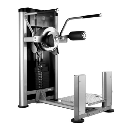
- Page 1 L340 Instrucciones de montaje y utilización Instructions for assembly and use Instructions de montage et d’utilisation Hinweise zur Montage und Benutzung...
- Page 2 L340 INSTRUCCIONES DE SEGURIDAD.- Rogamos leer estas instrucciones atentamente, antes del montaje y del primer uso. Obtendrá importantes informaciones para su seguridad, así como para el uso y para el mantenimiento del aparato de ejercicio. Guardar cuidadosamente las instrucciones para su información, así como para los trabajos de mantenimiento o los pedidos de piezas de repuesto.
-
Page 3: Safety Instructions
SAFETY INSTRUCTIONS Please read these instructions carefully before assembling and using the equipment. They contain important information for your safety and for the use and maintenance of the exercise equipment. Keep the instructions safe for future reference and maintenance tasks as well as for ordering spare parts. -
Page 4: Instructions De Sécurité
INSTRUCTIONS DE SÉCURITÉ - Nous recommandons de lire attentivement ces instructions avant de procéder au montage et d’utiliser l'appareil pour la première fois. Ce manuel contient des informations importantes relatives à la sécurité, à l’usage et à l’entretien de la machine d’exercice. Conserver soigneusement ces instructions à... - Page 5 SICHERHEITSHINWEISE.- Bitte lesen Sie diese Hinweise vor der Montage und ersten Benutzung des Geräts aufmerksam. Hier finden Sie wichtige Informationen zu Ihrer Sicherheit, zur Benutzung und zur Wartung Ihres Trainingsgeräts. Bewahren Sie diese Hinweise sorgfältig auf, um sie jederzeit zum Nachschlagen oder für erforderliche Informationen zur Wartung oder Bestellung von Ersatzteilen zur Hand zu haben.
- Page 6 Saque la unidad de la caja, compruebe e identifique las piezas con respecto al listado de la Fig.A y Fig.B, para asegurarse de que no falta ninguna pieza, para el montaje del equipo, en la primera fase. Take the unit out of its box, check and identify the parts against the list in Fig.A and Fig.B to ensure that there are no missing parts for the initial assembly stage of the equipment.
- Page 8 Fig.B Nº M-5x12 M-10x100 M-10x90 M-10x25 M-6x12 M-10x30 M-10 M-10...
- Page 9 INSTRUCCIONES DE MONTAJE.- NOTA: La descripción de las piezas con respecto a las figuras, corresponden siempre a la posición de la persona en el equipo para la realización del ejercicio. INSTRUCTIONS FOR ASSEMBLY.- NOTE: The description of the parts with respect to the figures always corresponds to the position the person adopts on the equipment when exercising.
- Page 10 Fig.2 Enrosque los tacos de nivelación (31) en el soporte (3) Fig.2. A continuación coloque el soporte (3) y atorníllelo al soporte (2) Fig.2, únalos con los tornillos (70) junto con las arandelas (82). Thread the levelling feet (31) onto the support (3), Fig.2. Next, position bracket (3) and secure it to the support (2) Fig.2, using screws (70 along with the washers (82).
- Page 11 Fig.3 Introduzca los ejes (51) en el apoyo de pies (4) Fig.3. Posiciónelo en los orificios inferiores del soporte (3) y atornille con los tornillos (79). Insert the shafts (51) into the footrest (4), Fig.3. Position it on the bottom holes of the support (3) and tighten using screws (79) Introduire les axes (51) dans l’appuie-pieds (4) Fig.3.
- Page 12 Fig.4 Coloque el extremo superior del hidráulico (56) en el soporte (3) Fig.4, atornille con la tuerca (85). Insert the top end of the hydraulic (56)arm into the bracket (3), Fig.4, tighten using nut (85). Positionner l’extrémité supérieure du bras hydraulique (56) dans le support (3) Fig.4, et visser avec l’écrou (85). Setzen Sie das obere Ende des Hydraulikelements (56) in an die Stütze (3) (Abb.
- Page 13 Fig.5 Coloque la protección izquierda (13) del apoyo pies (4) Fig.5. Atorníllela con los tornillos (78) junto con las arandelas (81). Coloque la protección derecha (14) del apoyo pies (4) Fig.5. Atorníllela con los tornillos (78) junto con las arandelas (81). Place the left-hand guard (13) on the footrest (4), Fig.5.
- Page 14 Fig.6 En primer lugar introduzca la arandela separadora (68) en el eje del soporte (1). Posicione el soporte piernas (5) en el eje del soporte (1) como le muestra la Fig.6. Atorníllelo al eje con la arandela de aluminio (47) y el tornillo (79) Fig.6 First fit the spacer washer (68) onto the shaft for support (1).
- Page 15 Fig.7 Sitúe el soporte lateral izquierdo (10) en la parte izquierda del soporte (1) Fig.7, atorníllelo con los tornillos (75) junto con las arandelas (82). A continuación coloque el soporte lateral derecho (11) en la parte derecha del soporte (1) Fig.7, atorníllelo con los tornillos (75) junto con las arandelas (82).
- Page 16 Fig.8 Sitúe el tope de pesas (38) en la torre de pesas (1) Fig.8 introduzca las barras de pesas (50). A continuación coloque las pesas (27); (26); (25), siempre las de mayor peso en la parte inferior, por ultimo coloque la pesa de guía con su barra selectora (34), atornille las barras de pesas por la parte superior con las arandelas (82) y los tornillos (75).
- Page 17 Fig.9 Atornille la parte inferior de la polea (16) Fig.9, en pesa de guía (34), coja una punta del cable (41) y páselo por las poleas superiores e inferiores y atorníllelo a la leva interna (8) Fig.9, con el tornillo (76). Pase la otra punta del cable (41) por las poleas superiores e inferiores y atorníllelo a la leva externa (8) Fig.9, con el tornillo (76).
- Page 18 Fig.10 Introduzca la carcasa delantera (46) Fig.10, desde la parte superior en dirección de la flecha en la torre de pesas (1). Coloque los insertos (61) a los dos lados de la torre. Posicione la tapa de cierre levas (12) en el soporte (1) Fig.10, atorníllela con los tornillos (78) y las arandelas (81). Fit the front casing (46) onto the weight stack (1), Fig.10, from the top in the direction of the arrow.
- Page 19 Fig.11 Introduzca la carcasa trasera (64) Fig.10, desde la parte superior en dirección de la flecha en la torre de pesas (1). Fit the rear casing (50) onto the weight stack (1), Fig.10, from the top in the direction of the arrow. Insérer la partie postérieure (64) Fig.10, par le haut en direction de la flèche dans la tour de poids (1).
- Page 20 Fig.12 Introduzca la carcasa superior (63) Fig.12, desde la parte superior en dirección de la flecha en la torre de pesas (1). Coloque las arandelas (65) y los tornillos (66). Fit the top casing (63) onto the weight stack (1), Fig.12, from the top in the direction of the arrow. Fit the washers (65) and screws (66).
-
Page 21: Muy Importante
Fig.13 Posicione la arandela (53) en el eje del soporte (5) Fig.13, a continuación introduzca el rodillo (55), la arandela (53), la arandela de aluminio (47) y atornille con el tornillo (79). Fit washer (53) onto the shaft for support (5), Fig.13, then fit the roller (55), washer (53), aluminium washer (47) and tighten using screw (79). - Page 22 L340...
- Page 23 Para pedido de repuesto: Indicar el código de la pieza y la cantidad To order replacement parts: State the part code and Quantity Pour commander des pièces de rechange: Indiquer le code de la pièce de rechange et la quantité désirée Bei der Bestellung von Ersatzteilen: Bitte Teile-Code und Menge angeben.
- Page 24 BH HIPOWER SPAIN BH HIPOWER PORTUGAL BH HIPOWER FRANCE MAQUINASPORT, S.A. EXERCYCLE,S.L. (Manufacturer) 27 bis, Route de Pitoys Zona Industrial Giesteira P.O.BOX 195 64600 ANGLET Terreirinho 3750-325 Agueda 01080 VITORIA (SPAIN) Tél.: +33 05 59 42 04 71 (PORTUGAL) Tel.: +34 945 29 02 58 Fax: +33 05 59 50 10 83 Tel.: +351 234 729 510 Fax: +34 945 29 00 49...
- Page 25 * Applies to defects from the manufacturer only. FOR WARRANTY REPAIRS, PLEASE DO NOT TAKE YOUR MACHINE BACK TO THE RETAIL STORE. CONTACT BH FITNESS FIRST. BH North America Corporation 20155 Ellipse Foothill Ranch, CA 92610 Phone: 949.206.0330;...