Thermaltake Commander G41 Mode D'emploi
Table des Matières
Liens rapides
© 2014 Thermaltake Technology Co., Ltd. All Rights Reserved. 2014.01
All other registered trademarks belong to their respective companies.
Tested To Comply
With FCC Standards
FOR HOME OR OFFICE USE
www.thermaltake.com
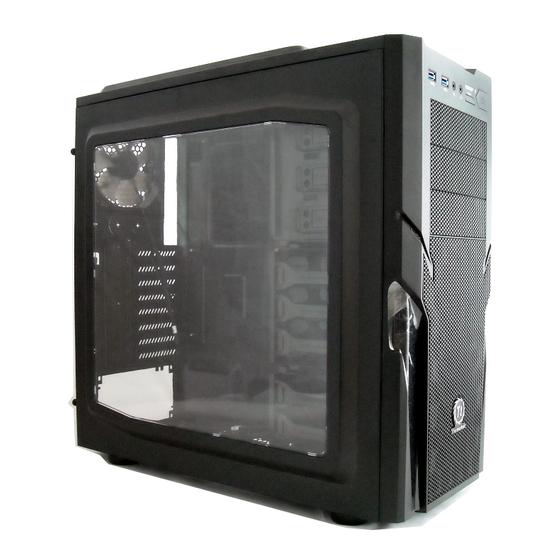
Commander
G41
User's Manual
Benutzerhandbuch
Mode d'emploi
Manual del usuario
Manuale dell'utente
Manual do Utilizador
安裝說明書
用戶手冊
ユーザーズマニュアル
Руководство пользователя
kullanıcı elkitabı
(EEE Yönetmeliğine Uygundur)
คู ่ ม ื อ การใช้
Table des Matières

Manuels Connexes pour Thermaltake Commander G41


Sommaire des Matières pour Thermaltake Commander G41
- Page 1 用戶手冊 ユーザーズマニュアル Руководство пользователя kullanıcı elkitabı (EEE Yönetmeliğine Uygundur) © 2014 Thermaltake Technology Co., Ltd. All Rights Reserved. 2014.01 คู ่ ม ื อ การใช้ All other registered trademarks belong to their respective companies. www.thermaltake.com Tested To Comply With FCC Standards...
-
Page 2: Table Des Matières
5.25" To 3.5" Bay Cover Audio Connection 14-17 Buzzer Motherboard Alarm Chapter 4. Other Cable Tie Settle Cable Thermaltake Power Supply Series (Optional) Front Fan Screw #6-32*28mm Screw M3*5mm Motherboard / FDD / 2.5" HDD Screw #6-32*6mm 5.25" to 3.5" Cage Screw M3*8mm... -
Page 3: Warning And Notice
Warning and Notice CPU Cooler Height Limitation VGA ( Add- on card) Length Limitation Atenção!! - Limite de altura para o dissipador do CPU: O limite de altura para o dissipador do CPU é 185 mm (7,3 polegadas). - Limite de comprimento para VGA (placa gráfica): O limite de comprimento para VGA (placa gráfica) é... -
Page 4: Side Panel Disassembly
Motherboard Installation Side Panel Disassembly English / 繁體中文 / 1. Lay down the chassis. 1. 將機殼平放。 English / 繁體中文 2. Install the motherboard in proper location and 2. 將主機板放置在合適的位置並用零件包中之螺絲 Remove the screws on the back of the chassis, secure it with screws. 移除機殼後方螺絲,將側窗打開... -
Page 5: Psu Installation
PSU Installation 5.25" Device Installation English / 1. Pull out the front panel. 2. Remove the 5.25” drive bay cover. 3. Slide the 5.25” device into the drive bay to lock the device. Note: Press the 5.25” tool-free mechanism to unlock the device. -
Page 6: External 3.5" Device Installation
External 3.5” Device Installation 繁體中文 / 1. 拉面板底部,將面板從機殼本體拆下。 2. 移除5.25”擴充槽檔板 3. 將5.25”裝置至適當的位置 注意: 如需移除5.25”裝置,先按壓5.25”無螺機機構,再將5.25”裝置往前推出。 English / 繁體中文 / 1. Remove the 5.25” mesh cover. 1. 移除5.25”擴充槽檔板 简体中文 / 2. Secure the 3.5” device on the adapter by screws. 2. 將3.5”裝置放入轉接磁架並用螺絲固定3.5”裝置 3. -
Page 7: 2.5" Hdd Installation
3.5” & 2.5” HDD Installation PCI Card Installation 2.5" HDD 3.5" HDD English / 繁體中文 / English / 繁體中文 / 1. Pull the HDD tray out. 1. 將硬碟托盤取出 1. Loosen the screws with a screwdriver. 1. 用螺絲起子將螺絲取下. 2. Place the 2.5” or 3.5” hard drive on the tray and 2. -
Page 8: 240Mm Radiator Installation
Leads Installation Guide 240mm Radiator Installation English Leads Installation Guide Case LED Connection / On the front of the case, you can find some LEDs and switch leads. Please consult your user manual of your motherboard manufacturer, then connect these leads to the panel header on the motherboard. USB 3.0 connection / 1. - Page 9 Español 繁體中文 Guía de Instalación de Cables 線材安裝說明 Conexión del LED de la caja / En la parte frontal de la caja, encontrará algunos LED y cables de interruptores. Consulte el 機殼LED連接方式 / 在機殼前方的面板後面,可以找到一些LED與開關線材(POWER Switch….),請參考主機板使用說明書, manual del usuario del fabricante de la placa madre, a continuación conecte estos cables al conector de la placa madre. 並將機殼上的線材正確地連接到主機板上,這些線材通常都會印有標籤在上面,如果沒有的話,請找出機殼前方面板上線材原...
-
Page 10: Thermaltake Power Supply Series (Optional)
Quality From Within sağladığı kullanım kılavuzuna bakın ve daha sonra, bu ara kabloları, anakart üzerindeki panel bağlantı noktalarına bağlayın. Every power supply units from Thermaltake should pass a very strict quality control before sent to USB 3.0 Bağlantısı / customers, including BIT(Burn-in-test) for over 8 continuous hour in a 45℃ room to test if a unit can run 1.