Table des Matières
Publicité
Les langues disponibles
Les langues disponibles
Liens rapides
Betriebsanleitung
Operating instructions
Notice technique
Manual de instrucciones
Istruzioni per l'uso
Instrukcja eksploatacji
FloCo-Top-1C / -2C
Version: 01.2022.0
ID: 900.000.1000
Copyright 2022 AFRISO-EURO-INDEX GmbH. Alle Rechte vorbehalten.
in Verbindung mit einem
PA-Schlauch 4 x 1 mm
FloCo-Top-2CM Optimum MC-18
MVV TB
C 2.15.23
EN 12514-2
FloCo-Top-1C Si
FloCo-Top-2CM Si
FloCo-Top-2CM MS-5
Publicité
Table des Matières

Manuels Connexes pour Afriso EURO-INDEX FloCo-Top-1C -2C


Sommaire des Matières pour Afriso EURO-INDEX FloCo-Top-1C -2C
- Page 1 Betriebsanleitung Operating instructions Notice technique Manual de instrucciones Istruzioni per l’uso Instrukcja eksploatacji FloCo-Top-1C / -2C FloCo-Top-1C Si FloCo-Top-2CM Si FloCo-Top-2CM Optimum MC-18 FloCo-Top-2CM MS-5 Copyright 2022 AFRISO-EURO-INDEX GmbH. Alle Rechte vorbehalten. MVV TB C 2.15.23 EN 12514-2 in Verbindung mit einem PA-Schlauch 4 x 1 mm Version: 01.2022.0...
- Page 2 Betriebsanleitung Automatischer Heizölentlüfter FloCo-Top-1C / -2C FloCo-Top-1C Si FloCo-Top-2CM Si FloCo-Top-2CM Optimum MC-18 FloCo-Top-2CM MS-5 Copyright 2022 AFRISO-EURO-INDEX GmbH. Alle Rechte vorbehalten. MVV TB C 2.15.23 EN 12514-2 in Verbindung mit einem PA-Schlauch 4 x 1 mm Version: 01.2022.0 ID: 900.000.1000...
- Page 3 Über diese Betriebsanleitung Über diese Betriebsanleitung Diese Betriebsanleitung beschreibt die automatischen Heizölentlüfter mit integriertem Filtereinsatz der Reihe „FloCo-Top-C“ (im Folgenden auch „Pro- dukt“). Diese Betriebsanleitung ist Teil des Produkts. • Sie dürfen das Produkt erst benutzen, wenn Sie die Betriebsanleitung vollständig gelesen und verstanden haben.
- Page 4 Informationen zur Sicherheit Informationen zur Sicherheit Warnhinweise und Gefahrenklassen In dieser Betriebsanleitung finden Sie Warnhinweise, die auf potenzielle Gefahren und Risiken aufmerksam machen. Zusätzlich zu den Anweisungen in dieser Betriebsanleitung müssen Sie alle am Einsatzort des Produktes gel- tenden Bestimmungen, Normen und Sicherheitsvorschriften beachten. Stel- len Sie vor Verwendung des Produktes sicher, dass Ihnen alle Bestimmun- gen, Normen und Sicherheitsvorschriften bekannt sind und dass sie befolgt werden.
-
Page 5: Informationen Zur Sicherheit
Informationen zur Sicherheit Bestimmungsgemäße Verwendung Dieses Produkt eignet sich ausschließlich für den Einsatz in Einstrangsyste- men mit Rücklaufzuführung zur kontinuierlichen Entlüftung folgender Brenn- stoffe in Heizölverbraucheranlagen: • Heizöl EL nach DIN 51603-1 und nach DIN SPEC 51603-6 mit 5 - 30 % Fettsäure-Methylester (FAME) nach EN 14214 •... -
Page 6: Vorhersehbare Fehlanwendung
Informationen zur Sicherheit Vorhersehbare Fehlanwendung Das Produkt darf insbesondere in folgenden Fällen und für folgende Zwecke nicht angewendet werden: • Einsatz in unverdünnten Additiven, Alkoholen und Säuren • Druckbetrieb mit Brennstoffförderaggregat • Einsatz im Außenbereich Qualifikation des Personals Montage, Inbetriebnahme, Wartung und Außerbetriebnahme dieses Pro- dukts dürfen nur von einem qualifizierten Fachbetrieb vorgenommen werden, der über eine entsprechende Zertifizierung verfügt und folgende Anforderun- gen erfüllt:... -
Page 7: Transport Und Lagerung
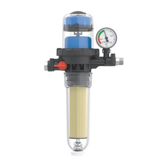
Transport und Lagerung Transport und Lagerung Das Produkt kann durch unsachgemäßen Transport und Lagerung beschä- digt werden. HINWEIS UNSACHGEMÄSSE HANDHABUNG • Stellen Sie sicher, dass während des Transports und der Lagerung des Pro- dukts die spezifizierten Umgebungsbedingungen eingehalten werden. • Benutzen Sie für den Transport die Originalverpackung. - Page 8 Produktbeschreibung Produktbeschreibung Das Produkt (nur bei Typ -2C/-2CM) hat eine Filtertasse mit einem integrier- ten Entleerventil, damit der Brennstoff abgelassen werden kann. Das Ent- leerventil ermöglicht einen Notbetrieb (beispielsweise aus einem Kanister). Sie können auch eine Prüfarmatur für die Dichtheitsprüfung des gesamten Systems anschließen.
- Page 9 Produktbeschreibung Funktion Die Brennerpumpe saugt durch den Filtereinsatz den flüssigen Brennstoff aus dem Tank an. Der nicht über die Brennerdüse verbrannte Brennstoff wird über den Rücklauf zum Entlüfter zurückgeführt und erneut über den Vorlauf dem Brenner zugeführt. Nur die tatsächlich verbrannte Menge Brennstoff wird aus dem Tank nachgesaugt und dem entlüfteten Brennstoff beige- mischt.
- Page 10 Produktbeschreibung Varianten A. Typ -1C Si mit Sinterkunststoff- C. Typ -2CM Optimum MC-18 mit Filtereinsatz (50 - 70 μm, 116 cm² Opticlean-Feinstfiltereinsatz MC- Filterfläche) 18 (5 μm, 1850 cm² Filterfläche), lange Filtertasse B. Typ -2CM Si mit Sinterkunststoff- Filtereinsatz (50 - 70 μm, 116 cm² D.
-
Page 11: Zulassungsdokumente, Bescheinigungen, Erklärungen
Produktbeschreibung Zulassungsdokumente, Bescheinigungen, Erklärungen Das Produkt ist vom TÜV geprüft (Bericht Nummer 968/FSP 2170.01/21). Technische Daten Parameter Wert Allgemeine Daten Abmessungen (B x H x T) - Typ: -1C 184 x 223 x 109 mm - Typ: -2CM 184 x 253 x 109 mm - Typ: -2CM Optimum 184 x 340 x 109 mm Anschluss Brenner... -
Page 12: Montage
Montage Montage Das Produkt wird vor dem Brenner installiert. Das Produkt darf über oder unter dem maximalen Füllstand des Tanks ein- gebaut werden. Wenn die entsprechenden örtlichen Gegebenheiten vorhanden sind, kann die Saugleitung mit stetigem Gefälle zum Tank hin verlegt werden. Querschnitt der Saugleitung ermitteln Bei Umstellung von Zweistranganlagen auf Einstrang-Betrieb sinkt die Strö- mungsgeschwindigkeit des Brennstoffs in der Saugleitung. - Page 13 Montage Düsen- Rohr- Saughöhe H Ø durchsatz Innen < 2,5 kg/h Ø 4 mm (3 l/h) Ø 6 mm > 100 > 100 > 100 Ø 8 mm > 100 > 100 > 100 > 100 > 100 5 kg/h Ø...
- Page 14 Montage 5.2.2 Maximale Saugleitungslänge bei tieferliegender Leitung 1. Montieren Sie ein Antiheberventil, um ein Austreten (Aushebern) von flüssigem Brennstoff bei undichter Saugleitung und höher liegendem Füllstand im Tank zu verhindern. A. Kolben-Antiheberventil „KAV“ B. Membran-Antiheberventil „MAV“ C. H = Absicherungs- höhe „KAV“...
-
Page 15: Produkt Montieren
Montage Produkt montieren HINWEIS FUNKTIONSUNFÄHIGES PRODUKT • Stellen Sie sicher, dass Sie die Brennerschläuche der Vor- und Rücklauflei- tung nicht vertauschen. Nichtbeachtung dieser Anweisungen kann zu Sachschäden führen. Stellen Sie sicher, dass die Umgebungsbedingungen eingehalten wer- den. Stellen Sie sicher, dass das Schwimmergehäuse senkrecht nach oben zeigt. - Page 16 Montage Saugleitung montieren HINWEIS UNDICHTHEIT DES PRODUKTS • Stellen Sie sicher, dass Sie eine Rohrverschraubung nach DIN 2353 mit zylindrischem Einschraubgewinde (G-Gewinde) verwenden und die Rohrverschraubung mit einer Flachdichtung oder mit geeignetem Kleber eindichten. Verwendung von Teflonband oder Hanf ist nicht zulässig. Nichtbeachtung dieser Anweisungen kann zu Sachschäden führen.
- Page 17 Montage FloCo-Top-2C 1. Dichten Sie die Saugleitung in das Innengewinde G des Gehäuses, mit zylindrischer Rohrverschraubung G nach DIN 2353 ein. Das Anzugs- moment beträgt 40 ±10 Nm. Wenn Sie die Saugleitung mit der beiliegenden Rohrverschraubung ein- dichten, liegt das Anzugsmoment für Ø 6 mm bei 18 ±3 Nm, für Ø 8 mm bei 15 ±5 Nm und für Ø...
- Page 18 Montage 5.6.1 Druckverlust bei Verwendung eines sauberen Filtereinsatzes Durchfluss [l/h] FloCo-Top-C...
- Page 19 Montage Entlüftungsschlauch anschließen Um Geruchsbelästigungen durch die abgeschiedene Luft zu vermeiden, kön- nen Sie einen Entlüftungsschlauch anschließen. A. Schlauchanschluss mit O-Ring 1. Führen Sie den Entlüftungsschlauch entlang der Saugleitung zum Tank zurück. 2. Fixieren Sie den Entlüftungsschlauch mit Kabelbindern. 3. Bringen Sie das andere Ende des Entlüftungsschlauchs an der Entlüf- tungsleitung oder am Rücklaufanschluss der Entnahmearmatur des Tanks an.
- Page 20 Betrieb Betrieb Flüssigkeitsstand im Schwimmergehäuse Der Flüssigkeitsstand stellt sich in Abhängigkeit von den anlagebedingten Betriebsbedingungen ein und liegt im Saugbetrieb bei circa 20 - 50 mm. Bei höher liegendem Flüssigkeitsstand kann es zu einem vollständig mit Brenn- stoff gefüllten Schwimmergehäuse kommen. Wenn sich die Betriebsbedin- gungen beispielsweise durch sinkenden Flüssigkeitsstand im Tank ändern, bildet sich wieder ein Luftpolster im Schwimmergehäuse.
- Page 21 Wartung Wartung Wartungsintervalle HINWEIS UNGEEIGNETE REINIGUNGSMITTEL • Stellen Sie sicher, dass Sie bei der Reinigung der Kunststoffteile lösemittel- freie Reinigungsmittel verwenden. Nichtbeachtung dieser Anweisungen kann zu Sachschäden führen. Zeitpunkt Tätigkeit Bei Bedarf Reinigen Sie die Kunststoffteile mit einer wässri- gen Seifenlauge Jährlich oder bei Bedarf Tauschen Sie den Filtereinsatz, siehe "Filterein- satz tauschen"...
- Page 22 Wartung Wartungstätigkeiten 7.2.1 Filtereinsatz tauschen 1. Stellen Sie ein geeignetes Gefäß (mit einem Fassungsvermögen von mindestens 0,5 Liter) unter die Filtertasse. Ø 6 mm FloCo-Top-C...
- Page 23 Wartung 2. Entleeren Sie die Filtertasse vor dem Austausch des Filtereinsat- zes. FloCo-Top-C...
- Page 24 Wartung 7.2.2 Filtereinsatz einbauen FloCo-Top-C...
- Page 25 Wartung 7.2.3 Brennerschläuche ersetzen Stellen Sie sicher, dass der Rücklauf und die Schwimmerkammer vor dem Ersetzen der Brennerschläuche entleert wurden. 1. Entleeren Sie die Filtertasse (siehe Kapitel "Filtereinsatz tauschen"). 2. Drücken Sie den roten Schieber (A) mit Hilfe eines geeigneten Werk- zeugs (beispielsweise Schraubendreher) nach oben und halten Sie ihn in...
- Page 26 Störungsbeseitigung Störungsbeseitigung Störungen, die nicht durch die im Kapitel beschriebenen Maßnahmen besei- tigt werden können, dürfen nur durch den Hersteller oder Fachkräfte beho- ben werden. Problem Mögliche Ursache Fehlerbehebung Starke Schaumbildung Undichtheit in der Saug- Führen Sie eine Dicht- in der Schwimmerkam- leitung heitsprüfung der Saug- mer durch zu viel einge-...
- Page 27 Störungsbeseitigung Problem Mögliche Ursache Fehlerbehebung Flüssigkeitssäule kann Geringfügige Undicht- Dichten Sie die zylindri- nicht angezogen wer- heiten (beispielsweise sche Rohrverschrau- den oder reißt ständig an Verschraubungen bung mit Kupfer-Flach- oder der Entnahmear- dichtungen luftdicht ein matur) können zu einem Verwenden Sie bei wei- Lufteintritt in die Saug- chem oder halb hartem leitung führen, auch im...
-
Page 28: Außerbetriebnahme Und Entsorgung
Außerbetriebnahme und Entsorgung Außerbetriebnahme und Entsorgung Entsorgen Sie das Produkt nach den geltenden Bestimmungen, Normen und Sicherheitsvorschriften. Filtereinsätze dürfen nicht über den Hausmüll entsorgt werden. 1. Demontieren Sie das Produkt (siehe Kapitel "Montage" in umgekehrter Reihenfolge). 2. Entsorgen Sie das Produkt. Rücksendung Vor einer Rücksendung Ihres Produkts müssen Sie sich mit uns in Verbin- dung setzen (service@afriso.de). - Page 29 Ersatzteile und Zubehör Ersatzteile und Zubehör HINWEIS UNGEEIGNETE TEILE • Verwenden Sie nur Original Ersatz- und Zubehörteile des Herstellers. Nichtbeachtung dieser Anweisung kann zu Sachschäden führen. Produkt Artikelbezeichnung Art.-Nr. Abbildung Automatischer Heizölentlüfter mit integ- 70155 Siehe Kapitel "Vari- riertem Filter „FloCo-Top-1C Si“ anten".
-
Page 30: Ersatzteile Und Zubehör
Ersatzteile und Zubehör Ersatzteile und Zubehör Artikelbezeichnung Art.-Nr. Abbildung Filtertasse kurz 20277 Filtertasse kurz 20288 (mit Entleereinrichtung) Filtertasse Optimum 20289 (mit Entleereinrichtung) Ersatz-Unterdruckmano- 70034 meter Anzeigebereich: -0,7 ... +0,9 bar Rohrverschraubung nach DIN 2353 mit Kupfer-Flach- dichtung: Rohr Ø... - Page 31 Ersatzteile und Zubehör Artikelbezeichnung Art.-Nr. Abbildung Opticlean 20308 Feinfilter kurz, 20 - 35 μm, MS-5 Opticlean 20319 Feinstfilter kurz, 5 - 20 μm, MC-7 Opticlean 20318 Feinstfilter lang, 5 - 20 μm, MC-18 Sikusieb Kurz, 50 - 70 μm blau 20045...
- Page 32 Operating instructions Automatic fuel oil de-aerator FloCo-Top-1C / -2C FloCo-Top-1C Si FloCo-Top-2CM Si FloCo-Top-2CM Optimum MC-18 FloCo-Top-2CM MS-5 Copyright 2022 AFRISO-EURO-INDEX GmbH. All rights reserved. MVV TB C 2.15.23 EN 12514-2 in conjunction with a PA hose 4 x 1 mm Version: 01.2022.0...
- Page 33 About these operating instructions About these operating instructions These operating instructions describe the automatic fuel oil de-aerators with integrated filter insert of the series "FloCo-Top-C" (also referred to as "prod- uct" in these operating instructions). These operating instructions are part of the product.
- Page 34 Information on safety Information on safety Safety messages and hazard categories These operating instructions contain safety messages to alert you to poten- tial hazards and risks. In addition to the instructions provided in these oper- ating instructions, you must comply with all directives, standards and safety regulations applicable at the installation site of the product.
-
Page 35: Information On Safety
Information on safety Intended use This product may only be used in single-line systems with return pipe con- nection for continuous de-aeration of the following fuels in fuel oil consuming systems: Fuel oil EL as per DIN 51603-1 and as per DIN SPEC 51603-6 with •... -
Page 36: Predictable Incorrect Application
Information on safety Predictable incorrect application The product must never be used in the following cases and for the following purposes: • Use with undiluted additives, alcohols and acids • Pressure operation with fuel pumping system • Outdoor use Qualification of personnel This product may only be mounted, commissioned, maintained and decom- missioned by a qualified, specialised company which has all required certifi- cations and which meets the following requirements:... -
Page 37: Transport And Storage
Transport and storage Transport and storage The product may be damaged as a result of improper transport or storage. NOTICE INCORRECT HANDLING • Verify compliance with the specified ambient conditions during transport or storage of the product. • Use the original packaging when transporting the product. •... - Page 38 Product description Product description The product (type -2C/-2CM only) has a filter cup with an integrated drain valve so that the fuel can be drained. The drain valve allows for emergency operation (for example, from a can). You can also connect a tester for the tightness test of the entire system. Overview A.
-
Page 39: Product Description
Product description Function The burner pump sucks the liquid fuel from the tank via the filter insert. The fuel not burnt by the burner nozzle is returned to the vent via the return line and then resupplied to the burner via the flow line. Only the amount of fuel actually burnt is taken from the tank and added to the de-aerated fuel. - Page 40 Product description Versions A. Type -1C Si with sintered plastic C. Type -2CM Optimum MC-18 with filter insert (50 - 70 μm, 116 cm² Opticlean ultra-fine filter insert filter surface) MC-18 (5 μm, 1850 cm² filter sur- face), long filter cup B.
-
Page 41: Approvals, Conformities, Certifications
Product description Approvals, conformities, certifications The product is TÜV-tested (report number 968/FSP 2170.01/21). Technical data Parameter Value General specifications Dimensions (W x H x D) - Type: -1C 184 x 223 x 109 mm - Type: -2CM 184 x 253 x 109 mm - Type: -2CM Optimum 184 x 340 x 109 mm Connection burner... - Page 42 Mounting Mounting Install the product upstream of the burner. The product may be installed above or below the maximum tank level. The suction line can be implemented with a steady gradient to the tank if the conditions on site permit this. Determining the cross section of the suction line When dual-pipe systems are converted to single-pipe operation, the flow rate of the fuel in the suction line is reduced.
- Page 43 Mounting Nozzle Inner Suction height H [m] Ø throughput pipe < 2.5 kg/h Ø 4 mm (3 l/h) Ø 6 mm > 100 > 100 > 100 Ø 8 mm > 100 > 100 > 100 > 100 > 100 5 kg/h Ø...
- Page 44 Mounting 5.2.2 Maximum suction line length in the case of a lower lying line 1. Install an anti-siphon valve to keep liquid fuel from escaping (siphoning) in the case of an untight suction line and a higher level in the tank. A.
-
Page 45: Mounting The Product
Mounting Mounting the product NOTICE INOPERABLE PRODUCT • Verify that you do not interchange the burner hoses for the flow and return lines. Failure to follow these instructions can result in equipment damage. Verify compliance with the specified ambient conditions. ... - Page 46 Mounting Mounting the suction line NOTICE LEAKING PRODUCT • Verify that you use a screwed pipe connection as per DIN 2353 with cylin- drical thread (G thread) and seal the screwed pipe connection with a flat gasket or with suitable glue. Do not use Teflon tape or hemp. Failure to follow these instructions can result in equipment damage.
- Page 47 Mounting FloCo-Top-2C 1. Mount the suction line into the female thread G of the housing with a cylindrical screwed pipe connection G as per DIN 2353. The tightening torque is 40 ±10 Nm. If you seal the suction line with the enclosed screwed pipe connection, the tightening torque for Ø...
- Page 48 Mounting 5.6.1 Pressure loss with use of clean filter insert Flow rate [l/h] FloCo-Top-C...
- Page 49 Mounting Connecting the vent hose To avoid odours from the separated air, you can connect a vent hose. A. Hose connection with O ring 1. Route the vent hose back to the tank next to the suction line. 2. Fixate the vent hose with cable ties. 3.
- Page 50 Operation Operation Liquid level in the float housing The liquid level depends on the operating conditions of the system and amounts to approximately 20-50 mm in suction mode. If the liquid level is higher, the float housing may be completely filled with fuel. When the operat- ing conditions change, for example, decreasing liquid level in the tank, the air cushion is formed again in the float housing.
-
Page 51: Maintenance Intervals
Maintenance Maintenance Maintenance intervals NOTICE UNSUITABLE CLEANING AGENTS • Verify that you use only cleaning agents which do not contain solvents for cleaning the plastic parts. Failure to follow these instructions can result in equipment damage. When Activity If required Clean the plastic parts with soap suds Annually or if required Replace the filter insert, see "Replacing the filter... -
Page 52: Maintenance Activities
Maintenance Maintenance activities 7.2.1 Replacing the filter insert 1. Place a suitable container with a capacity of at least 0.5 l below the filter cup. Ø 6 mm FloCo-Top-C... - Page 53 Maintenance 2. Drain the filter cup before replac- ing the filter insert. FloCo-Top-C...
- Page 54 Maintenance 7.2.2 Mounting the filter insert FloCo-Top-C...
- Page 55 Maintenance 7.2.3 Replacing the burner hoses Verify that the return line and the float chamber are completely drained prior to replacing the burner hoses. 1. Drain the filter cup (see chapter "Replacing the filter insert"). 2. Press up the red slider (A) using a suitable tool (for example, screwdriver) and hold it in this position.
- Page 56 Troubleshooting Troubleshooting Any malfunctions that cannot be removed by means of the measures described in this chapter may only be repaired by the manufacturer or by qualified persons. Problem Possible reason Repair Heavy formation of Suction line not tight Perform a tightness test foam in the float cham- of the suction line (vac- ber due to excessive...
- Page 57 Troubleshooting Problem Possible reason Repair Liquid column cannot be Small leaks (for exam- Use a cylindrical sucked in or steady flow ple, at the screw con- screwed pipe connec- keeps being interrupted nections or the with- tion and seal them with drawal fitting) can cause flat copper gaskets (air- air to get into the suction...
-
Page 58: Returning The Device
Decommissioning, disposal Decommissioning, disposal Dispose of the product in compliance with all applicable directives, standards and safety regulations. Filter inserts must not be disposed of together with the normal household waste. 1. Dismount the product (see chapter "Mounting", reverse sequence of steps). - Page 59 Spare parts and accessories Spare parts and accessories NOTICE UNSUITABLE PARTS • Only use genuine spare parts and accessories provided by the manufac- turer. Failure to follow these instructions can result in equipment damage. Product Product designation Part no. Figure Automatic fuel oil de-aerator with inte- 70155 See chapter "Ver-...
-
Page 60: Spare Parts And Accessories
Spare parts and accessories Spare parts and accessories Product designation Part no. Figure Filter cup short 20277 Filter cup short 20288 (with drain system) Filter cup Optimum (with 20289 drain system) Spare vacuum gauge 70034 Range: -0.7 ... +0.9 bar ... - Page 61 Spare parts and accessories Product designation Part no. Figure Opticlean 20308 Fine filter short, 20 - 35 μm, MS-5 Opticlean 20319 Ultra-fine filter short, 5 - 20 μm, MC-7 Opticlean 20318 Ultra-fine filter long, 5 - 20 μm, MC-18 Sintered plastic sieve Short, 50 - 70 μm blue...
-
Page 62: Purgeur D'air Automatique Pour Fuel
Notice technique Purgeur d'air automatique pour fuel FloCo-Top-1C / -2C FloCo-Top-1C Si FloCo-Top-2CM Si FloCo-Top-2CM Optimum MC-18 FloCo-Top-2CM MS-5 Copyright 2022 AFRISO-EURO-INDEX GmbH. Tous droits réservés. MVV TB C 2.15.23 EN 12514-2 En liaison avec un tube PA 4 x 1 mm Version: 01.2022.0... - Page 63 La présente notice technique La présente notice technique Cette notice technique contient la description des purgeurs d'air automa- tiques avec élément filtrant intégré pour fuel de la série "FloCo-Top-C" (dénommé ci-après "produit"). Cette notice technique fait partie du produit. • Utilisez le produit seulement après que vous aurez lu et compris intégra- lement la notice technique.
-
Page 64: Consignes De Sécurité Et Classes De Risques
Informations sur la sécurité Informations sur la sécurité Consignes de sécurité et classes de risques Cette notice technique contient des consignes de sécurité destinées à attirer l'attention sur les dangers et les risques. Outre les instructions contenues dans cette notice technique, il faut vous assurer de l'observation de tous les règlements, normes et consignes de sécurité... -
Page 65: Informations Sur La Sécurité
Informations sur la sécurité Avant d'utiliser le produit, assurez-vous que le produit est adapté à l'usage que vous prévoyez. À cet effet, tenez compte au moins de ce qui suit : • Tous les règlements, normes et consignes de sécurité sur le lieu d'instal- lation •... -
Page 66: Qualification Du Personnel
Informations sur la sécurité Qualification du personnel Le montage, la mise en service, la maintenance et la mise hors service de ce produit ne peuvent être effectuées que par une entreprise spécialisée quali- fiée possédant la certification appropriée et répondant aux exigences suivantes : •... -
Page 67: Transport Et Stockage
Transport et stockage Transport et stockage Un transport et un stockage inadéquats risquent de causer des dommages au produit. AVIS MANUTENTION INAPPROPRIÉE • Assurez-vous que les conditions ambiantes spécifiées sont respectées pen- dant le transport et le stockage. • Utilisez l'emballage d'origine pour le transport. •... - Page 68 Description du produit Description du produit Le produit (uniquement pour le type -2C/ -2CM) possède un bol de filtre avec une vanne de vidange intégrée afin que le combustible puisse être vidangé. La vanne de vidange permet un fonctionnement d'urgence (par exemple à partir d'un bidon).
-
Page 69: Fonctionnement
Description du produit Fonctionnement La pompe du brûleur aspire le combustible liquide du réservoir à travers l'élé- ment filtrant. Le combustible qui n'a pas été brûlé par le gicleur du brûleur est transporté vers le purgeur via le retour et acheminé vers le brûleur via le départ. - Page 70 Description du produit Variantes A. Type -1C Si avec élément filtrant C. Type -2CM Optimum MC-18 avec en matière plastique (50 - 70 μm, Opticlean élément filtrant ultra-fin 116 cm² surface de filtration) MC-18 (5 μm, 1850 cm² surface de filtration), bol de filtre long B.
-
Page 71: Agréments, Certificats, Déclarations
Description du produit Agréments, certificats, déclarations Le produit est testé par le TÜV (rapport no° 968/FSP 2170.01/21). Caractéristiques techniques Paramètre Valeur Caractéristiques générales Dimensions (L x H x P) - Type: -1C 184 x 223 x 109 mm - Type: -2CM 184 x 253 x 109 mm - Type: -2CM Optimum 184 x 340 x 109 mm... -
Page 72: Montage
Montage Montage Le produit est à installer en amont du brûleur. Le produit peut être monté au-dessus ou en dessous du niveau maximum du réservoir. Si les conditions locales appropriées sont disponibles, la conduite d'aspira- tion peut être posée avec une pente régulière vers le réservoir. Déterminer la section de la conduite d'aspiration En cas de conversion d'un système à... - Page 73 Montage Débit de Ø inté- Hauteur d'aspiration H gicleur rieur de conduite < 2,5 kg/h Ø 4 mm (3 l/h) Ø 6 mm > 100 > 100 > 100 Ø 8 mm > 100 > 100 > 100 > 100 >...
-
Page 74: Longueur Maximale De La Conduite D'aspiration Pour Une Conduite Plus Profonde
Montage Longueur maximale de la conduite d'aspiration pour 5.2.2 une conduite plus profonde 1. Installez une valve anti-siphon pour éviter un écoulement éventuel (siphonnage) de combustible liquide en cas de fuite dans la conduite d'aspiration ou de niveau de remplissage supérieur dans le réservoir. A. -
Page 75: Montage Du Produit
Montage Montage du produit AVIS PRODUIT NON OPÉRATIONNEL • Assurez-vous de ne pas invertir les tuyaux du brûleur pour les conduites départ et retour. La non-observation de ces instructions peut causer des dommages maté- riels. Assurez-vous que les conditions ambiantes sont respectées. ... -
Page 76: Montage De La Conduite D'aspiration
Montage Montage de la conduite d'aspiration AVIS INÉTANCHÉITÉ DU PRODUIT • Utilisez un raccord tube selon DIN 2353 avec filetage cylindrique (filetage G) et assurez l'étanchéité du raccord tube avec une garniture plate ou une colle adaptée. N'utilisez pas du ruban téflon ou du chanvre. La non-observation de ces instructions peut causer des dommages maté- riels. - Page 77 Montage FloCo-Top-2C 1. Utilisez un raccord cylindrique G selon DIN 2353 afin de raccorder le tube d'aspiration au taraudage G du boîtier. Le couple de serrage est de 40 ± 10 Nm Si vous utilisez le raccord tube inclus, le couple de serrage pour Ø 6 mm est de 18 ±3 Nm, le couple de serrage pour Ø...
- Page 78 Montage 5.6.1 Perte de pression avec un élément filtrant propre Débit [l/h] FloCo-Top-C...
- Page 79 Montage Liaison du tuyau de purge Pour éviter les désagréments dus aux mauvaises odeurs, il est possible de raccorder un tuyau de purge. A. Raccord tuyau avec anneau torique 1. Posez le tuyau de purge le long de la conduite d'aspiration vers le réser- voir.
- Page 80 Service Service Niveau du liquide dans la chambre du flotteur Le niveau du liquide dépend des caractéristiques techniques de fonctionne- ment de l'installation ; en mode aspiration il se situe à environ 20 - 50 mm. Lorsque le niveau de liquide est plus élevé, la chambre du flotteur peut être plein de combustible.
-
Page 81: Intervalles De Maintenance
Maintenance Maintenance Intervalles de maintenance AVIS NETTOYANTS INADAPTÉS • Utilisez uniquement des nettoyants sans solvant pour nettoyer les pièces en plastique. La non-observation de ces instructions peut causer des dommages maté- riels. Quand Opération Si nécessaire Nettoyez les parties plastiques avec mousse de savon Annuellement ou si Remplacez l'élément filtrant, voir "Replacer l'élé-... -
Page 82: Opérations De Maintenance
Maintenance Opérations de maintenance 7.2.1 Replacer l'élément filtrant 1. Positionnez un récipient d'une capacité d'au moins 0,5 litres sous le bol de filtre. Ø 6 mm FloCo-Top-C... - Page 83 Maintenance 2. Videz le bol de filtre avant de rem- placer l'élément filtrant. FloCo-Top-C...
-
Page 84: Montage D'élément Filtrant
Maintenance 7.2.2 Montage d'élément filtrant FloCo-Top-C... -
Page 85: Remplacer Les Tuyaux De Brûleur
Maintenance 7.2.3 Remplacer les tuyaux de brûleur Videz le circuit de retour ainsi que la chambre de flotteur avant de pro- céder à l'échange des tuyaux de brûleur. 1. Videz le bol de filtre (voir chapitre "Replacer l'élément filtrant"). 2. Utilisez un outil approprié (par exemple un tourne- vis) pour pousser la pièce rouge (A) vers le haut et... - Page 86 Suppression des dérangements Suppression des dérangements Les dérangements ne figurant pas dans les mesures décrites dans ce cha- pitre doivent être éliminés uniquement par le fabricant ou par des personnes qualifiées. Problème Cause possible Action corrective Moussage fort dans la Fuite dans la conduite Effectuez un examen chambre de flotteur...
-
Page 87: Suppression Des Dérangements
Suppression des dérangements Problème Cause possible Action corrective La colonne de liquide Une mauvaise étan- Employez un raccord n'est pas aspirée ou l'ali- chéité (par ex. sur les cylindrique avec joint mentation se coupe raccords ou sur l'unité plat en cuivre (herméti- régulièrement de vidange) conduise à... -
Page 88: Mise Hors Service Et Élimination
Mise hors service et élimination Mise hors service et élimination Pour éliminer le produit, conformez-vous aux règlements, normes et consignes de sécurité en vigueur. Les éléments filtrants ne doivent pas être éliminés avec les ordures ména- gères. 1. Démontez le produit (voir chapitre "Montage", effectuez les opérations en ordre inverse). -
Page 89: Pièces Inadaptées
Pièces détachées et accessoires Pièces détachées et accessoires AVIS PIÈCES INADAPTÉES • N'utilisez que des accessoires et des pièces détachées d'origine provenant du fabricant. La non-observation de ces instructions peut causer des dommages maté- riels. Produit Désignation de l'article Référence Figure Purgeur d'air automatique avec filtre 70155 Voir... -
Page 90: Pièces Détachées Et Accessoires
Pièces détachées et accessoires Pièces détachées et accessoires Désignation de l'article Référence Figure Bol de filtre court 20277 Bol de filtre court (avec dis- 20288 positif de vidange) Bol de filtre Optimum (avec 20289 dispositif de vidange) Manomètre de dépression, 70034 rechange Plage d'affichage : ... - Page 91 Pièces détachées et accessoires Désignation de l'article Référence Figure Opticlean 20308 Filtre fin, court, 20 - 35 μm, MS-5 Opticlean 20319 Filtre ultra-fin court, 5 - 20 μm, MC-7 Opticlean 20318 Filtre ultra-fin long, 5 - 20 μm, long MC-18 Tamis Siku Court, 50 - 70 μm bleu...
- Page 92 Manual de instrucciones Purgador de aire automático FloCo-Top-1C / -2C FloCo-Top-1C Si FloCo-Top-2CM Si FloCo-Top-2CM Optimum MC-18 MC-18 FloCo-Top-2CM MS-5 Copyright 2022 AFRISO-EURO-INDEX GmbH. Se reservan todos los derechos. MVV TB C 2.15.23 EN 12514-2 in Verbindung mit einem PA-Schlauch 4 x 1 mm Versión: 01.2022.0...
- Page 93 Sobre este manual de instrucciones Sobre este manual de instrucciones Este manual de instrucciones describe los purgadores de aire automáticos para combustible con inserto filtrante integrado serie"FloCo-Top-C" (en lo sucesivo también referido como "producto"). Este manual de instrucciones forma parte del producto. •...
- Page 94 Informaciones de seguridad Informaciones de seguridad Advertencias y clases de peligro Este manual de instrucciones comprende advertencias que indican peligros y riesgos potenciales. Además de las prescripciones contenidas en este manual de instrucciones se observarán todas las disposiciones, normas e indicaciones de seguridad en el lugar de utilización del producto.
-
Page 95: Informaciones De Seguridad
Informaciones de seguridad Uso previsto Este producto se emplea exclusivamente en sistemas monotubulares con alimentación de retorno para la purga de aire de los de combustible siguien- tes en instalaciones de consumo de combustible: Combustible EL según DIN 51603-1 y DIN SPEC 51603-6 con un •... -
Page 96: Mal Uso Razonablemente Previsible
Informaciones de seguridad Mal uso razonablemente previsible El producto no se aplicará en los siguientes casos y para los fines siguientes: • Uso con aditivos no diluidos, alcoholes y ácidos • Operación a presión con unidad transportadora • Uso en áreas exteriores Calificación del personal Montaje, puesta en marcha, mantenimiento y puesta fuera de servicio de este producto serán sólo realizados por empresas calificadas en la especia-... -
Page 97: Transporte Y Almacenaje
Transporte y almacenaje Transporte y almacenaje El producto puede resultar dañado por transporte y almacenaje inadecuado. AVISO MANEJO NO PREVISTO • Asegúrese de que durante el transporte y el almacenaje del producto se observan las condiciones ambientales especificadas. • Utilice para el transporte el embalaje original. •... - Page 98 Descripción del producto Descripción del producto El producto (sólo tipo -2C/-2CM) dispone de un cárter de filtro con válvula de vaciado integrado para poder drenar combustible. Das Entleerventil ermögli- cht einen Notbetrieb (beispielsweise aus einem Kanister). Además, puede conectar un accesorio de ensayo para la comprobar la estanqueidad del sistema completo.
-
Page 99: Descripción Del Producto
Descripción del producto Funcionamiento La bomba del quemador aspira el combustible líquido del tanque a través del inserto filtrante. El combustible no quemado por la boquilla del quemador se retorna a través del retorno y se alimenta nuevamente al quemador sobre la salida. - Page 100 Descripción del producto Variantes A. Tipo -1C Si con inserto filtrante de C. Tipo -2CM Optimum MC-18 con plástico sinterizado (50 - 70 μm, inserto de filtro finísimo Opticlean 116 cm² superficie filtrante) MC-18 (5 μm, 1850 cm² superfi- cie filtrante), cárter de filtro largo B.
-
Page 101: Datos Técnicos
Descripción del producto Licencias, certificaciones, descripciones El producto dispone de aprobación TÜV (nº de informe 968 FSP 2170,01/ 21). Datos técnicos Parámetros Valor Datos generales Dimensiones (An x Al x P) - Tipo: -1C 184 x 223 x 109 mm - Tipo: -2CM 184 x 253 x 109 mm - Tipo: -2CM Optimum... - Page 102 Descripción del producto Parámetros Valor Material de caja Plástico, reforzado con fibra de vidrio Condiciones ambientales Temperatura ambiental durante la 0 ... 60 °C operación Temperatura de medio 0 ... 60 °C FloCo-Top-C...
- Page 103 Montaje Montaje El producto se instala delante del quemador. El producto puede ser instalado por encima o por debajo del nivel de llenado máximo del tanque. En caso de estar disponibles las condiciones locales correspondientes, el tubo de aspiración puede ser colocado con inclinación permanente hacia el tanque.
- Page 104 Montaje Rendi- Ø Inte- Altura de aspiración H miento de rior del tobera tubo < 2,5 kg/h Ø 4 mm (3 l/h) Ø 6 mm > 100 > 100 > 100 Ø 8 mm > 100 > 100 > 100 >...
- Page 105 Montaje Largo de tubo de aspiración máximo con tubo colocado 5.2.2 más bajo 1. Instale una válvula anti-sifón para evitar el vaciado de combustible líquido en caso de que el tubo de aspiración esté defectuoso y el nivel de combustible en el tanque esté superior. A.
-
Page 106: Montar El Producto
Montaje Montar el producto AVISO PRODUCTO INOPERATIVO • Asegúrese de no confundir los tubos de quemador de salida y retorno. El incumplimiento de estas prescripciones puede causar daños materia- les. Asegúrese de que se observan las condiciones ambientales. Asegúrese de que la caja de flotador se posiciona verticalmente hacia arriba. - Page 107 Montaje Montar tubo de aspiración AVISO PÉRDIDAS EN EL PRODUCTO • Asegúrese de que según DIN 2353 se emplea una rosca cilíndrica (rosca G) y de que se sella ésta con junta plana o pegamento adecuado. No se permite el uso de cinta de teflón o cáñamo. El incumplimiento de estas prescripciones puede causar daños materia- les.
- Page 108 Montaje FloCo-Top-2C 1. Selle el tubo de aspiración en la rosca interior G de la caja con unión roscada cilíndrica para tubo G según DIN 2353. El par de apriete es de 40 ±10 Nm. En el momento de sellar el tubo de aspiración en el racor roscado adjunto, el par de apriete para Ø...
- Page 109 Montaje 5.6.1 Pérdida de presión usando un inserto filtrante limpio Paso [l/h] FloCo-Top-C...
- Page 110 Montaje Conectar tubo flexible de purga de aire Para evitar molestias por olores resultantes del aire purgado puede conectar un tubo flexible de purga de aire. A. Conexión de tubo flexible con junta tórica 1. Retorne el tubo flexible de purga de aire a lo largo del tubo de aspiración. 2.
- Page 111 Operación Operación Nivel del líquido en la caja de flotado El nivel de líquido depende de las condiciones de funcionamiento de la ins- talación y varia en el modo de aspiración entre aprox. 20 - 50 mm. En caso de un nivel del líquido superior, la caja de flotador puede llenarse completa- mente de combustible.
-
Page 112: Intervalos De Mantenimiento
Mantenimiento Mantenimiento Intervalos de mantenimiento AVISO DETERGENTES INAPROPIADOS • Asegúrese de que se emplean detergentes libres de disolventes para la lim- pieza de las piezas de plástico. El incumplimiento de estas prescripciones puede causar daños materia- les. Momento Actividad A demanda Limpie las partes de plástico con una lejía jabo- nosa acuosa Anualmente o a... -
Page 113: Actividades De Mantenimiento
Mantenimiento Actividades de mantenimiento 7.2.1 Recambiar inserto filtrante 1. Coloque recipiente adecuado debajo del cárter de filtro (con un volu- men mínimo de 0,5 litros). Ø 6 mm FloCo-Top-C... - Page 114 Mantenimiento 2. Vacíe el cárter de filtro antes de cambiar el inserto filtrante. FloCo-Top-C...
- Page 115 Mantenimiento 7.2.2 Montar inserto filtrante FloCo-Top-C...
- Page 116 Mantenimiento 7.2.3 Sustituya tubos flexibles de quemador Asegúrese de que el retorno y la cámara flotante se vaciaron ante el recambio de los tubos flexibles del quemador. 1. Vacíe el cárter de filtro (véase capítulo "Recambiar inserto filtrante"). 2. Empuje la corredera (A) mediante herramienta apropiada (por ejemplo destornillador) hacia...
- Page 117 Eliminación de errores Eliminación de errores Todos los errores que no se hacen eliminar por las medidas descritas en el capítulo, sólo deberán ser eliminados por el fabricante o técnicos especiali- zados. Problema Causa posible Eliminación del fallo Mucha espuma de Pérdidas en el tubo de Compruebe estanquei- aceite en la cámara del...
-
Page 118: Eliminación De Errores
Eliminación de errores Problema Causa posible Eliminación del fallo La columna de fluidos Pequeñas fugas (p.e., Selle herméticamente no hace estabilizarse o en uniones roscadas o las uniones roscadas de se interrumpe continua- valvulería) pueden lle- tubo cilíndricas con jun- mente var a la entrada de aire tas planas de cobre... - Page 119 Puesta fuera de servicio y eliminación de residuos Puesta fuera de servicio y eliminación de residuos Elimine el producto conforme a las disposiciones, normas e indicaciones de seguridad vigentes. Insertos filtrantes no deben ser eliminados a través de la basura doméstica. 1.
- Page 120 Piezas de repuesto y accesorios Piezas de repuesto y accesorios AVISO PIEZAS INAPROPIADAS • Emplee únicamente piezas de repuesto y accesorios del fabricante. El incumplimiento de estas prescripciones puede causar daños materia- les. Producto Denominación de artículo Nº art. Figura Purgador de aire automático con filtro 70155 Véase capítulo...
-
Page 121: Piezas De Repuesto Y Accesorios
Piezas de repuesto y accesorios Piezas de repuesto y accesorios Denominación de artículo Nº art. Figura Cárter de filtro corto 20277 Cárter de filtro corto (con 20288 dispositivo de vaciado) Cárter de filtro Optimum 20289 (con dispositivo de vaciado) Manómetro de vacío de 70034 reserva Gama de indicación: ... - Page 122 Piezas de repuesto y accesorios Denominación de artículo Nº art. Figura Opticlean 20308 Filtro fino corto, 20 - 35 μm, MS-5 Opticlean 20319 Filtro finísimo corto, 5 - 20 μm, MC-7 Opticlean 20318 Filtro finísimo largo 5 - 20 μm, MC-18 Tamiz Siku Corto, 50 - 70 μm azul...
- Page 123 Istruzioni per l’uso Neutralizzatore aria automatico FloCo-Top-1C / -2C FloCo-Top-1C Si FloCo-Top-2CM Si FloCo-Top-2CM Optimum MC-18 FloCo-Top-2CM MS-5 Copyright 2022 AFRISO-EURO-INDEX GmbH. Tutti i diritti sono riservati. MVV TB C 2.15.23 EN 12514-2 in combinazione con un tubo PA 4 x 1 mm Versione: 01.2022.0...
- Page 124 Su queste Istruzioni per l'uso Su queste Istruzioni per l'uso Queste Istruzioni per l'uso descrivono i neutralizzatori aria automatici per gasolio con inserto filtro integrato della serie "FloCo-Top-C" (nel prosieguo anche "prodotto"). Le presenti Istruzioni per lʼuso costituiscono parte del pro- dotto.
- Page 125 Informazioni sulla sicurezza Informazioni sulla sicurezza Avvertenze e classi di pericolosità Queste Istruzioni per l'uso contengono avvertenze che richiamano l'atten- zione a pericoli e rischi. In aggiunta alle avvertenze riportate nelle Istruzioni per l'uso sono da rispettare tutte le disposizioni, prescrizioni e norme di sicu- rezza vigenti sul posto d'impiego del prodotto.
-
Page 126: Informazioni Sulla Sicurezza
Informazioni sulla sicurezza Uso conforme Questo prodotto è stato adatto esclusivamente allʼimpiego in sistemi a linea singola con riconduzione del ritorno, per la neutralizzazione continua dei seguenti carburanti in impianti di combustione del gasolio: • gasolio EL secondo DIN 51603-1 e DIN SPEC 51603-6 con il 5 - 30 % di esteri metilici di acidi grassi (FAME) secondo EN 14214 •... -
Page 127: Uso Improprio Prevedibile
Informazioni sulla sicurezza Uso improprio prevedibile Il prodotto non può essere utilizzato in particolar modo nei seguenti casi e per i seguenti scopi: • impiego in additivi, alcool e acidi non diluiti • Esercizio in pressione con aggregato di convogliamento del carburante •... -
Page 128: Trasporto E Magazzinaggio
Trasporto e magazzinaggio Trasporto e magazzinaggio I prodotto può riportare danni da trasporto e magazzinaggio non adeguato. AVVISO UTILIZZO IMPROPRIO • Assicurare che le condizioni ambientali specificate per il trasporto e il magaz- zinaggio siano rispettate. • Per il trasporto, utilizzate l'imballaggio originale. •... - Page 129 Descrizione del prodotto Descrizione del prodotto Il prodotto (solo per il tipo -2C/-2CM) ha una tazza filtro con valvola di eva- cuazione integrata per poter evacuare il carburante. La valvola di evacua- zione rende possibile l'esercizio di emergenza (ad esempio, da una tanica). È...
-
Page 130: Descrizione Del Prodotto
Descrizione del prodotto Funzionamento La pompa del bruciatore aspira il carburante liquido dal serbatoio attraverso il filtro. Il carburante non bruciato dall'ugello del bruciatore viene riconvogliato allo sfiato tramite il ritorno e poi nuovamente al bruciatore tramite la mandata. Solo la quantità di carburante effettivamente bruciata viene aspirata dal ser- batoio e aggiunta al carburante sfiatato. - Page 131 Descrizione del prodotto Varianti A. Tipo -1C Si con inserto filtro in C. Tipo -2CM Optimum MC-18 con materia plastica sinterizzata (50 - inserto filtro finissimo Opticlean 70 μm, superficie filtro 116 cm²) MC-18 (5 μm, superficie filtro1850 cm²), a tazza lunga B.
-
Page 132: Specifiche Tecniche
Descrizione del prodotto Documenti di omologazione, certificati, dichiarazioni Il prodotto è omologato dal TÜV (rapporto Nº 968/FSP 2170.01/21). Specifiche tecniche Parametri Valore Dati generali Dimensioni (largh x alt x prof) - Tipo: -1C 184 x 223 x 109 mm - Tipo: -2CM 184 x 253 x 109 mm - Tipo: -2CM Optimum 184 x 340 x 109 mm... - Page 133 Descrizione del prodotto Parametri Valore Materiale contenitore Materia plastica, rinforzata con fibra di vetro Condizioni ambiente Temperatura ambiente - Funziona- 0 ... 60 °C mento Temperatura mezzo 0 ... 60 °C FloCo-Top-C...
- Page 134 Montaggio Montaggio Il prodotto si installa a monte del bruciatore. Il prodotto si può montare solo sopra o sotto il livello di riempimento max del serbatoio. Il condotto di aspirazione, condizioni d'installazione permettendo, si può posare come condotto di aspirazione con pendenza continua verso il serba- toio.
- Page 135 Montaggio Capacità Ø interno Altezza di aspirazione H [m] ugelli ugelli < 2,5 kg/h Ø 4 mm (3 l/h) Ø 6 mm > 100 > 100 > 100 Ø 8 mm > 100 > 100 > 100 > 100 > 100 5 kg/h Ø...
- Page 136 Montaggio 5.2.2 Lunghezza max del condotto di aspirazione con condotto posato in basso 1. Per evitare la fuoriuscita di carburante liquido nel caso di condotto d'aspirazione non stagno e livello di riempimento più alto nel serbatoio è necessario montare una valvola anti-sifone. A.
-
Page 137: Montaggio Dell'apparecchio
Montaggio Montaggio dell’apparecchio AVVISO PRODOTTO NON FUNZIONANTE • Assicuratevi di non avere scambiato i tubi di mandata e ritorno. La mancata osservanza di queste indicazioni può causare danni materiali. Assicurare che le condizioni ambientali siano rispettate. Verificate che la camera con galleggiante verticale sia rivolta verso lʼalto 1. - Page 138 Montaggio Montare il condotto di aspirazione AVVISO PRODOTTO NON STAGNO • Assicuratevi di avere utilizzato un avvitamento per tubi a norma DIN 2353 con avvitamento cilindrico (avvitamento tipo G) per la sigillatura e di averlo sigillato a tenuta piatta oppure con un adesivo adatto. Non è per- messo usare un nastro teflon o canapa.
- Page 139 Montaggio FloCo-Top-2C 1. Sigillare il condotto di aspirazione nellʼavvitamento femmina G dellʼinvo- lucro con l'avvitamento per tubo cilindrico G secondo DIN 2353. La cop- pia di serraggio è di 40 ±10 Nm. Se usate l'avvitamento per tubo a corredo per sigillare il condotto di aspi- razione, la coppia di serraggio per Ø...
- Page 140 Montaggio Perdita di pressione dovuta all’utilizzo di un inserto 5.6.1 filtro pulito Portata [l/h] FloCo-Top-C...
- Page 141 Montaggio Collegare il tubo di sfiato Per evitare odori causati dall'aria espulsa è possibile collegare un tubo di sfiato. A. Attacco tubo con O-ring 1. Posare il tubo di sfiato verso il serbatoio conducendolo lungo il condotto d'aspirazione. 2. Fissare il tubo di sfiato con fermacavi. 3.
- Page 142 Operazione Operazione Livello di liquido nella camera con galleggiante Il livello del liquido dipende dalle condizioni operative dell'impianto ed è pari a 20 - 50 mm in modalità di aspirazione. Se il livello di liquido è maggiore e il condotto di aspirazione è ben sigillato, la camera del galleggiante può riem- pirsi completamente di carburante.
-
Page 143: Intervalli Di Manutenzione
Manutenzione Manutenzione Intervalli di manutenzione AVVISO DETERGENTI NON ADATTI • Assicuratevi di usare detergenti esenti da solventi per la pulizia delle parti in materiale sintetico. La mancata osservanza di queste indicazioni può causare danni materiali. Data Attività All'occorrenza Pulire le parti di plastica con acqua e sapone. 1 x all'anno o all'occor- Sostituire l'inserto filtro, vedere ."Sostituire renza... -
Page 144: Interventi Di Manutenzione
Manutenzione Interventi di manutenzione 7.2.1 Sostituire l'inserto filtro 1. Disporre una vaschetta di raccolta adatta, con capienza di almeno 0,5 litri sotto la tazza filtro. Ø 6 mm FloCo-Top-C... - Page 145 Manutenzione 2. Svuotare la tazza del filtro prima di sostituire l'inserto filtro. FloCo-Top-C...
-
Page 146: Montare L'inserto Filtro
Manutenzione 7.2.2 Montare l'inserto filtro FloCo-Top-C... - Page 147 Manutenzione 7.2.3 Sostituire i tubi del bruciatore Assicuratevi che il ritorno e la camera del galleggiante siano stati svuo- tati prima di sostituire i tubi del bruciatore. 1. Svuotare la tazza del filtro (vedere il Cap. "Sostituire l'inserto filtro"). 2. Premere lo spintone rosso (A) verso l'alto con un utensile adatto (ad es., cacciavite) e mantenerlo...
- Page 148 Riparazione guasti Riparazione guasti I guasti non riparabili con le misure descritte nel capitolo devono essere ripa- rati dal fornitore o da personale specializzato. Problema Possibile causa Contromisure Forte formazione di Perdite del condotto di Eseguire una prova di schiuma di gasolio nella aspirazione tenuta del condotto camera del galleg-...
-
Page 149: Riparazione Guasti
Riparazione guasti Problema Possibile causa Contromisure La colonna di liquido Piccole perdite (even- Sigillare l'avvitamento non è aspirabile o conti- tualmente sugli avvita- tubo cilindrico con guar- nua a rompersi. menti o sul gruppo di nizioni piatte di rame a prelievo) causano la tenuta dʼaria nellʼinvolu- penetrazione di aria nel... -
Page 150: Smontaggio E Smaltimento
Smontaggio e smaltimento Smontaggio e smaltimento Smaltire il prodotto in osservanza delle disposizioni, norme e prescrizioni di sicurezza vigenti. I filtri e gli inserti filtro non vanno smaltiti con i rifiuti domestici. 1. Smontare il prodotto (si veda il Cap. "Montaggio", in ordine inverso). 2. - Page 151 Ricambi e accessori Ricambi e accessori AVVISO COMPONENTI NON IDONEI • Utilizzare solo pezzi di ricambio e accessori del produttore. La mancata osservanza di queste indicazioni può causare danni materiali. Prodotto Nome articolo Art. N° Figura Neutralizzatore aria automatico per 70155 Vedere il capitolo gasolio con...
-
Page 152: Ricambi E Accessori
Ricambi e accessori Ricambi e accessori Nome articolo Art. N° Figura Tazza filtro corta 20277 Tazza filtro corta (con 20288 dispositivo di evacuazione) Tazza filtro Optimum (con 20289 dispositivo di evacuazione) Vacuometro di ricambio 70034 Scala: -0,7 ... +0,9 bar ... - Page 153 Ricambi e accessori Nome articolo Art. N° Figura Opticlean 20308 Filtro fine corto, 20 - 35 μm, MS-5 Opticlean 20319 Filtro finissimo corto, 5 - 20 μm, MC-7 Opticlean 20318 Filtro finissimo lungo, 5 - 20 μm, MC-18 Vaglio Siku corto, 50-70 μm, blu...
-
Page 154: Instrukcja Eksploatacji
Instrukcja eksploatacji Automatyczny odpowietrznik oleju opałowego FloCo-Top-1C / -2C FloCo-Top-1C Si FloCo-Top-2CM Si FloCo-Top-2CM Optimum MC-18 FloCo-Top-2CM MS-5 Copyright 2022 AFRISO-EURO-INDEX GmbH. Wszelkie prawa zastrzeżone. MVV TB C 2.15.23 EN 12514-2 in Verbindung mit einem PA-Schlauch 4 x 1 mm Wersja: 01.2022.0... -
Page 155: Objaśnienia Do Niniejszej Instrukcji Eksploatacji
Objaśnienia do niniejszej instrukcji eksploatacji Objaśnienia do niniejszej instrukcji eksploatacji Niniejsza instrukcja eksploatacji opisuje automatyczne odpowietrzniki oleju opałowego zintegrowane z wkładem filtra i należące do typoszeregu „FloCo-Top-C” (poniżej zwane także produktem). Niniejsza instrukcja eksplo- atacji jest częścią produktu. • Produkt wolno użytkować dopiero po całkowitym przeczytaniu i pełnym zro- zumieniu instrukcji eksploatacji. - Page 156 Informacje na temat bezpieczeństwa Informacje na temat bezpieczeństwa Wskazówki ostrzegawcze i klasy zagrożenia Niniejsza instrukcja eksploatacji zawiera wskazówki ostrzegawcze zwracające uwagę na potencjalne zagrożenia oraz ryzyka. Poza zaleceniami zawartymi w niniejszej instrukcji eksploatacji trzeba przestrzegać wszystkich warunków, norm oraz przepisów bezpieczeństwa obowiązujących w miejscu użytkowania produktu.
-
Page 157: Stosowanie Zgodne Z Przeznaczeniem
Informacje na temat bezpieczeństwa Stosowanie zgodne z przeznaczeniem Ten produkt przeznaczony jest wyłącznie do stosowania w instalacjach jedno- rurowych z doprowadzeniem strumienia powrotnego i służy w instalacjach opa- lanych olejem do odpowietrzania w trybie ciągłym następujących paliw: • oleju opałowego EL według normy DIN 51603-1 oraz normy DIN SPEC 51603-6 zawierającego 5 - 30 % estrów metylowych kwasów tłuszczowych (FAME) zgodnie z normą... - Page 158 Informacje na temat bezpieczeństwa Przewidywalne błędne stosowanie Produktu nie wolno stosować w szczególności w następujących przypadkach i do następujących celów: • w kontakcie z nierozcieńczonymi dodatkami uszlachetniającymi, alkoholami i kwasami, • w trybie ciśnieniowym z agregatem do tłoczenia paliwa, • w zastosowaniach na zewnątrz Kwalifikacje personelu Czynności montażu, uruchamiania, konserwacji i wyłączania z eksploatacji tego produktu może wykonywać...
-
Page 159: Transport I Składowanie
Transport i składowanie Osobiste wyposażenie ochronne Należy zawsze stosować wymagane osobiste wyposażenie ochronne. Pod- czas czynności wykonywanych przy produkcie oraz z jego pomocą należy także uwzględnić, że w miejscu użytkowania mogą występować zagrożenia, których źródłem nie jest bezpośrednio sam produkt. Modyfikacje produktu Przy produkcie oraz z jego pomocą... -
Page 160: Opis Produktu
Opis produktu Opis produktu Produkt (tylko typ -2C/-2CM) jest wyposażony w naczynie filtra ze zintegrowa- nym zaworem spustowym umożliwiającym odprowadzanie paliwa. Zawór spu- stowy powala na pracę awaryjną (przykładowo przy wykorzystaniu kanistra). Można podłączyć też armaturę do kontroli szczelności całego układu. Przegląd A. - Page 161 Opis produktu Działanie Pompa palnika zasysa przez wkład filtra paliwo ciekłe ze zbiornika. Paliwo, które nie uległo spaleniu w dyszy palnika, jest zawracane za pośrednictwem powrotu do odpowietrznika i ponownie doprowadzane do palnika za pośred- nictwem zasilania. Ze zbiornika zasysane jest tylko uzupełniająco paliwo w ilości faktycznie spalonej, które stanowi następnie domieszkę...
- Page 162 Opis produktu Warianty A. typ -1C Si z wkładem filtra ze spie- C. typ -2CM Optimum MC-18 z wkła- kanego tworzywa sztucznego dem filtra ultradrobnego Opticlean (50 - 70 μm, 116 cm² powierzchni MC-18 (5 μm, 1 850 cm² filtra) powierzchni filtra), długie naczynie filtra B.
-
Page 163: Dane Techniczne
Opis produktu Dopuszczenia, certyfikaty, deklaracje Produkt został poddany badaniu przez Stowarzyszenie Nadzoru Technicznego TÜV (numer raportu 968/FSP 2170.01/21). Dane techniczne Parametr Wartość Dane ogólne wymiary (szerokość x wysokość x głębokość) - typ: -1C 184 x 223 x 109 mm - typ: -2CM 184 x 253 x 109 mm - typ: -2CM Optimum 184 x 340 x 109 mm... - Page 164 Opis produktu Parametr Wartość materiał korpusu tworzywo sztuczne, wzmocnione włóknem szklanym Warunki otoczenia temperatura otoczenia podczas pracy 0 ... 60 °C temperatura medium 0 ... 60 °C FloCo-Top-C...
- Page 165 Montaż Montaż Produkt jest instalowany przed palnikiem. Produkt może być montowany powyżej lub poniżej maksymalnego poziomu napełnienia zbiornika. W razie występowania odpowiednich warunków lokalnych przewód ssący może zostać ułożony ze stałym spadkiem w kierunku zbiornika. Wyznaczanie przekroju przewodu ssącego Przy przestawianiu instalacji dwururowych na tryb pracy jednorurowej spada prędkość...
- Page 166 Montaż Wysokość ssania H Przepusto- Ø wość dyszy wewnętr zna rury < 2,5 kg/h Ø 4 mm (3 l/h) Ø 6 mm > 100 > 100 > 100 Ø 8 mm > 100 > 100 > 100 > 100 > 100 5 kg/h Ø...
- Page 167 Montaż Maksymalna długość przewodu ssącego o obniżonym 5.2.2 poziomie 1. W celu zapobieżenia wyciekowi (zgłębnikowaniu) paliwa ciekłego w razie rozszczelnienia przewodu ssącego oraz wyższego poziomu napełnienia w zbiorniku należy zamontować zawór antylewarowy. A. tłokowy zawór antylewa- rowy „KAV“ B. membranowy zawór anty- lewarowy „MAV“...
-
Page 168: Montaż Produktu
Montaż Montaż produktu WSKAZÓWKA NIESPRAWNY PRODUKT • Należy upewnić się, że węże palnika na zasilaniu i powrocie nie zostały pod- mienione. Nieprzestrzeganie niniejszych zaleceń może doprowadzić do powstania szkód materialnych. Należy upewnić się, że są dotrzymywane warunki otoczenia. Należy upewnić się, że obudowa pływaka jest skierowana pionowo w górę. 1. - Page 169 Montaż Montaż przewodu ssącego WSKAZÓWKA NIESZCZELNOŚĆ PRODUKTU • Należy upewnić się, że stosowany jest śrubunek rurowy zgodny z normą DIN 2353 z gwintem wkręcanym cylindrycznym (gwint G), który jest uszczelniany przy pomocy uszczelki płaskiej lub odpowiedniego kleju. Sto- sowanie taśmy teflonowej lub konopii jest niedopuszczalne. Nieprzestrzeganie niniejszych zaleceń...
- Page 170 Montaż FloCo-Top-2C 1. Uszczelnić przewód ssący w gwincie wewnętrznym G obudowy śrubun- kiem rurowym z gwintem cylindrycznym G zgodnie z normą DIN 2353 . Moment dociągający wynosi 40 ±10 Nm. Przy uszczelnianiu przewodu ssącego załączonym śrubunkiem rurowym moment dociągający określany jest dla Ø 6 mm na 18 ±3 Nm, dla Ø 8 mm na 15 ±5 Nm oraz dla Ø...
- Page 171 Montaż 5.6.1 Spadek ciśnienia przy stosowaniu czystego wkładu filtra przepływ [l/h] FloCo-Top-C...
- Page 172 Montaż Podłączanie węża odpowietrzającego W celu uniknięcia uciążliwości powodowanych przez zapachy wydzielanego powietrza można podłączyć wąż odpowietrzający. A. przyłącze węża z pierścieniem uszczelniającym o przekroju okrą- głym 1. Wąż odpowietrzający poprowadzić wzdłuż przewodu ssącego do zbiornika. 2. Przymocować wąż odpowietrzający opaskami zaciskowymi. 3.
- Page 173 Eksploatacja Eksploatacja Poziom cieczy w obudowie pływaka Poziom cieczy zależy od warunków eksploatacyjnych instalacji i wynosi około 20 - 50 mm w trybie ssania. W razie wyższego poziomu cieczy paliwo może całkowicie zapełnić obudowę pływaka. Jeśli zmieniają się warunki eksploata- cyjne, na przykład przez obniżenie poziomu cieczy w zbiorniku, w obudowie pływaka tworzy się...
- Page 174 Konserwacja Konserwacja Okresy konserwacyjne WSKAZÓWKA NIEWŁAŚCIWE DETERGENTY • Należy upewnić się, że do czyszczenia elementów z tworzywa sztucznego stosowane są środki czyszczące nie zawierające rozpuszczalników. Nieprzestrzeganie niniejszych zaleceń może doprowadzić do powstania szkód materialnych. Termin Czynność W razie potrzeby Oczyścić elementy z tworzywa sztucznego przy użyciu roztworu wody z mydłem.
-
Page 175: Czynności Konserwacyjne
Konserwacja Czynności konserwacyjne 7.2.1 Wymiana wkładu filtra 1. Podstawić odpowiedni zasobnik (o pojemności co najmniej 0,5 l) pod naczynie filtra. Ø 6 mm FloCo-Top-C... - Page 176 Konserwacja 2. Opróżnić naczynie filtra przed wymianą wkładu filtra. FloCo-Top-C...
- Page 177 Konserwacja 7.2.2 Montaż wkładu filtra FloCo-Top-C...
- Page 178 Konserwacja 7.2.3 Wymiana węży palnika Należy upewnić się, że powrót i komora pływakowa zostały opróżnione przed wymianą węży palnika. 1. Opróżnić naczynie filtra (patrz rozdział "Wymiana wkładu filtra"). 2. Przycisnąć czerwony suwak (A) odpowiednim narzędziem (przykładowo wkrętakiem) w kierunku górnym i przytrzymać go w tej pozycji.
- Page 179 Usuwanie usterek Usuwanie usterek Usterki, których nie da się zlikwidować przy pomocy czynności opisanych w niniejszym rozdziale, może usuwać wyłącznie producent lub wykwalifikowani pracownicy. Problem Możliwa przyczyna Usuwanie usterek Silne spienianie w komo- Nieszczelność w prze- Wykonać próbę ciśnie- rze pływakowej ze wodzie ssącym.
-
Page 180: Usuwanie Usterek
Usuwanie usterek Problem Możliwa przyczyna Usuwanie usterek Brak możliwości zassa- Drobne nieszczelności Uszczelnić hermetycz- nia cieczy lub ciągłe zała- (przykładowo na śrubun- nie cylindryczne śrubunki mywanie się słupa cie- kach lub na armaturze rurowe przy pomocy czy. do poboru cieczy) mogą miedzianych uszczelek doprowadzić... -
Page 181: Wyłączenie Z Eksploatacji I Utylizacja
Wyłączenie z eksploatacji i utylizacja Wyłączenie z eksploatacji i utylizacja Produkt należy utylizować zgodnie z obowiązującymi warunkami, normami oraz przepisami bezpieczeństwa. Wkładów filtrów nie wolno utylizować wraz z odpadami bytowymi z gospo- darstw domowych. 1. Wykonać demontaż produktu (patrz rozdział "Montaż" w odwrotnej kolejno- ści). - Page 182 Części zamienne i wyposażenie dodatkowe Części zamienne i wyposażenie dodatkowe WSKAZÓWKA NIEWŁAŚCIWE CZĘŚCI • Należy stosować wyłącznie oryginalne części zamienne i wyposażenie dodat- kowe producenta. Nieprzestrzeganie niniejszego zalecenia może doprowadzić do powstania szkód materialnych. Produkt Nazwa artykułu Numer Ilustracja artykułu automatyczny odpowietrznik oleju opa- 70155 patrz rozdział...
-
Page 183: Części Zamienne I Wyposażenie Dodatkowe
Części zamienne i wyposażenie dodatkowe Części zamienne i wyposażenie dodatkowe Nazwa artykułu Numer artykułu Ilustracja naczynie filtra, krótkie 20277 naczynie filtra, krótkie 20288 (z układem opróżniania) naczynie filtra, Optimum 20289 (z układem opróżniania) zastępczy manometr podci- 70034 śnieniowy zakres wskazań: ... - Page 184 Części zamienne i wyposażenie dodatkowe Nazwa artykułu Numer artykułu Ilustracja Opticlean 20308 filtr drobny krótki, 20 - 35 μm, MS-5 Opticlean 20319 filtr ultradrobny krótki, 5 - 20 μm, MC-7 Opticlean 20318 filtr ultradrobny długi, 5 - 20 μm, MC-18 ...