Table des Matières
Publicité
Les langues disponibles
Les langues disponibles
Liens rapides
INSTALLATIEVOORSCHRIFT EN GEBRUIKERSHANDLEIDING NL/BE
INSTRUCTIONS FOR INSTALLATION AND OPERATION GB/IE
INSTALLATIONSVORSCHRIFT UND GEBRAUCHSANWEISUNG DE/AT/BE/LU/CH
INSTRUCTIONS D'INSTALLATION ET MODE D'EMPLOI FR/BE/LU/CH
NORME PER L'INSTALLAZIONE E INSTRUZIONE PER L'USO IT
MANUAL DE INSTALACIÓN Y GUÍA DEL USUARIO ES
INSTRUÇÔES DE INSTALAÇÂO E O INSTRUÇÂO PT
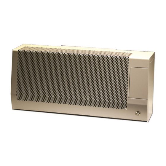
NL 31 STYLE
Bewahren Sie dieses Dokument sorgfältig auf
Conservez soigneusement cette notice
Conservare con cura uesto manuale dell'utente
Guarde cuidadosamente esta guía para el usuario
Conserva esta instruçâo cuidadosamente.
DRU VERWARMING B.V.
HOLLAND
NL 31
NL 51
Bewaar dit document zorgvuldig
Please retain this document carefully
957.539.08
Publicité
Chapitres
Table des Matières

Sommaire des Matières pour Dru Verwarming NL 31
- Page 1 NORME PER L’INSTALLAZIONE E INSTRUZIONE PER L’USO IT MANUAL DE INSTALACIÓN Y GUÍA DEL USUARIO ES INSTRUÇÔES DE INSTALAÇÂO E O INSTRUÇÂO PT NL 31 NL 31 STYLE NL 51 Bewaar dit document zorgvuldig Please retain this document carefully Bewahren Sie dieses Dokument sorgfältig auf Conservez soigneusement cette notice Conservare con cura uesto manuale dell’utente...
- Page 2 Hierbij verklaren wij dat de DRU modellen NL31 en NL51 in overeenstemming zijn met het CE type-onderzoekscertificaat E 1490 en dat zij voldoen aan de Europese richtlijn inzake gastoes- tellen 2009/142/EC. We here by declare that the DRU models NL31 and NL51 are in conformity with the types as described in EC type-certificate E 1490 and that they are in compliance with the European Council gas appliance directive 2009/142/EC.
-
Page 3: Table Des Matières
De standaard geveldoorvoer ..........2 Waakvlamstand ..............6 Installatie van de standaard geveldoorvoer ....2 Uitschakelen ................6 De geveldoorvoer met telescopische inlaatpijp ....3 Technische gegevens NL 31 ..........6 Installatie van de geveldoorvoer met Technische gegevens NL 51 ..........6 telescopische inlaatpijp ............3 Algemene opmerkingen ............7 Bevestiging van de montageplaat ........4... -
Page 4: Woord Vooraf
INSTALLATIE VOORSCHRIFT Woord vooraf Installatie aan een wand van onbrandbaar materiaal (fig. 1) Geachte klant, Het toestel kan hangend of staand worden geïnstalleerd. Houd er rekening mee dat boven het toestel minimaal 1 Vriendelijk bedankt voor de aankoop van dit DRU meter vrij ruimte nodig is voor voldoende warmteafvoer. -
Page 5: De Geveldoorvoer Met Telescopische Inlaatpijp
G3/8" 38c-981 fig. 1 G3/8" 38c-981 fig. 2 Type NL31 ø 230 3/8” Ø210 Ø110 NL31 STYLE ø 230 3/8” Ø210 Ø110 NL51 1228 ø 230 3/8” Ø210 Ø110 Tabel 1 NL 31 / NL 51... -
Page 6: Bevestiging Van De Montageplaat
INSTALLATIE VOORSCHRIFT Bevestiging van de montageplaat (fig. 3) Installatie van het binnenwerk (fig. 4) Let op: stel de montageplaat (2) waterpas, zorg ervoor dat Schuif de op lengte gemaakte uitlaatpijp in de rooster- de inlaatpijp naar buiten toe afloopt (1cm op 1 m) en dat opening. -
Page 7: In Bedrijf Stellen
10ºC. Indien dit niet gewenst is, dient het toestel uit- geschakeld te worden Uitschakelen Druktoets B (met symbool o ) indrukken. De gastoevoer naar de hoofd- en de waakvlambrander is dan gesloten. NL 31 / NL 51... -
Page 8: Gebruikershandleiding Nl 51
GEBRUIKERSHANDLEIDING GEBRUIKERSHANDLEIDING NL 51 TECHNISCHE GEGEVENS NL 31 Aansteken Type Knop A indrukken en linksom Gassoort draaien tot de kleine vlam . Branderdruk mbar zal het toestel ontsteken. Nom. Belasting (Hs) 4.00 3.70 4.00 Controleer of de waakvlam achter Nom. Belasting (Hi) 3.60... -
Page 9: Algemene Opmerkingen
Dit verdwijnt na enkele uren. Daarom raden wij u aan het toestel de eerste maal op de hoogste stand te stoken terwijl u tevens het vertrek waarin de kachel staat goed ventileert. NL 31 / NL 51... - Page 11 CONTENTS CONTENTS Important ................12 Foreword ................10 Operating instructions NL 31 .........13 Unpacking ................10 Lighting ..................13 Connection ................10 Temperature controle ............13 Instructions for installation ..........10 Pilot light setting ..............13 Type of gas ................10 Switching off ................13 Important ................10 Operating instructions NL 51 .........13 General .................10...
-
Page 12: Foreword
INSTRUCTIONS FOR INSTALLATION Foreword Installing the heater against a wall of incombustible material (fig. 1) Dear Customer, The appliance can be installed in a hanging or standing position. Allow at least 1 metre’s clearance above the We would like to thank you for buying this DRU prod- heater to enable sufficient heat circulation. -
Page 13: The Exterior Wall Duct With Telescopic Inlet Pipe
G3/8" 38c-981 fig. 1 G3/8" 38c-981 fig. 2 Type NL31 ø 230 3/8” Ø210 Ø110 NL31 STYLE ø 230 3/8” Ø210 Ø110 NL51 1228 ø 230 3/8” Ø210 Ø110 Table 1 NL 31 / NL 51... -
Page 14: Fastening The Mounting Sheet
INSTRUCTIONS FOR INSTALLATION Fastening the mounting sheet (fig. 3) into the outlet opening of the interior for support. Now slide the interior against the mounting sheet, taking care Caution: Level the mounting sheet, make sure that the that the turned-back edge of the mounting sheet fits into inlet pipe goes down towards the outside. -
Page 15: Operating Instructions Nl 31
10 ºC. If this is not required, the heater should be switched off. Switching off Press button B (with the symbol o ). The gas supply to both the main and the pilot burners is then switched off. NL 31 / NL 51... -
Page 16: Technical Data Nl 31
OPERATING INSTRUCTIONS TECHNICAL DATA NL 31 Type Type of gas Burner pressure mbar Nom. Load (Hs) 4.00 4.00 Nom. Load (Hi) 3.60 3.60 Nom. output 3.06 3.06 Consumption on full output m 0.381 0.151 Consumption on low output m 0.104 0.043... -
Page 17: General Notes
/ renovations done, you are advised to wait at least 6 weeks before lighting your fire, to allow the walls, floor and ceiling to dry out completely. NL 31 / NL 51... - Page 19 Temperatur regeln .............22 Material .................18 Zündflammenstand .............22 Giebeldurchfuhr in Standardausführung .......18 Ausschalten ................22 Installation der Standard Giebeldurchführung ....19 Technischen Daten NL 31 ..........22 Giebeldurchführung met Teleskopeinlassrohr ....19 Technischen Daten NL 51 ..........22 Installation der Giebeldurchführung mit Allgemeine Bemerkungen ..........23 Teleskopeinlassrohr ............19 Wartung und Reinigung ............23...
-
Page 20: Einige Kurze Worte
INSTALLATIONSVORSCHRIFT Einige kurze Worte Allgemein Das Gerät kann sowohl an eine Wand von nicht bren- Sehr geehrter Kunde, nbarem Material (z. B. Stein oder Beton), als auch an eineWand von brennbarem Material (z. B. Holz) installiert Herzlichen Dank für den Kauf dieses DRU Produktes. werden. -
Page 21: Installation Der Standard Giebeldurchführung
Einlassrohrs durch die Montageplatte (2) und sorgen G3/8" 38c-981 fig. 1 G3/8" 38c-981 fig. 2 Type NL31 ø 230 3/8” Ø210 Ø110 NL31 STYLE ø 230 3/8” Ø210 Ø110 NL51 1228 ø 230 3/8” Ø210 Ø110 Tabelle 1 NL 31 / NL 51... -
Page 22: Befestigung Der Montageplatte
INSTALLATIONSVORSCHRIFT Sie dafür, dass die eingelassenen Befestigungsbügel (5) auf für Holz ersetzen. der horizontalen Mittellinie liegen (siehe Markierung in • Bringen Sie an der Zimmerseite zwischen der der Montageplatte) und um die umgesetzte Montageplatte Montageplatte (2) und der Wand die Strahlen-Schutzplatte haken. -
Page 23: Inbetriebnahme
Drehen Sie nicht mit Gewalt an dem Knopf, muß das Gerät ausgeschaltet werden. weil der Mechanismus beschädigt werden könnte. Ausschalten Druckschalter B ( mit o ) eindrücken. Die Gaszufuhr zum Haupt- und Zündflammenbrenner ist dann geschlossen. NL 31 / NL 51... -
Page 24: Gebrauchsanweisung Nl 51
GEBRAUCHSANWEISUNG GEBRAUCHSANWEISUNG NL 51 TECHNISCHEN DATEN NL 31 Zündung Type Knopf A eindrücken und links herum Gassorte drehen, bis zum Zeichen Brennerdruck mbar wird das Gerät zünden. Nom. Belastung (Hs) 4.00 3.70 4.00 Kontrollieren Sie, ob die Zündflamme Nom. Belastung(Hi) 3.60... -
Page 25: Allgemeine Bemerkungen
Lackdämpfe verursacht und verschwindet nach einigen Stunden von selbst. Wir empfehlen Ihnen deshalb, das Gerät bei der ersten Inbetriebnahme in den höchsten Stand zu stellen, wobei Sie gleichzeitig den Raum, in dem der Ofen steht, gut lüften. NL 31 / NL 51... - Page 27 TABLE DES MATIÈRES Installation du manteau .............29 Introduction .................26 Important ................29 Déballage de l’appareil ............26 Branchementl ..............26 Mode d’emploi NL 31 ............29 Instructions d’ installation ..........26 Allumage ................29 Sorte de gaz .................26 Réglage de la température ..........29 Important ................26 Position veilleuse ..............29 Généralités .................26...
-
Page 28: Introduction
INSTRUCTIONS D’INSTALLATION Introduction Généralités L’appareil peut être aussi bien fixé à un mur fait en maté- riau ininflammable (comme la pierre ou le béton) qu’à un Cher client, mur en matériau inflammable (comme le bois). Nous vous remercions d’avoir acheté cet article fabriqué Installation à... -
Page 29: Installation Du Conduit Standard De Traversée De Façade
Faites glisser l’autre moitié de la conduite G3/8" 38c-981 fig. 1 G3/8" 38c-981 fig. 2 Type NL31 ø 230 3/8” Ø210 Ø110 NL31 STYLE ø 230 3/8” Ø210 Ø110 NL51 1228 ø 230 3/8” Ø210 Ø110 Tableau 1 NL 31 / NL 51... -
Page 30: Fixation De La Plaque De Montage
INSTRUCTIONS D’INSTALLATION d’amenée à travers la plaque de montage (2) en veillant à • Par ailleurs, remplacez l’écrou à cheville (8) (fig 3) par un ce que les colliers de fixation (5) se trouvent bien sur l’axe boulon fileté pour bois. horizontal (voir les repères dans la plaque de montage) et •... -
Page 31: Mise En Marche
10°C. Si on ne désire pas faire fonc- tionner cette sécurité, il convient de débrancher l’appareil. Extinction Appuyer sur le bouton B (repéré par le symbol o ). L’alimentation en gaz de la veilleuse et du brûleur est alors coupée. NL 31 / NL 51... -
Page 32: Allumage
MODE D’EMPLOI MODE D’EMPLOI NL 51 DONNÉES TECHNIQUES NL 31 Allumage Type Appuyez sur le bouton A Sorte de gaz tournez-le vers la gauche jusqu’au Pression de brûleur mbar petit . La position sert à allumer Puissance calorifique (Hs) 4.00 3.70... -
Page 33: Remarques Générales
Cette odeur disparaîtra après quelques heures. Nous vous conseillons de chauffer la première fois l’appareil au maximum en prenant soin de bien aérer la pièce où la cheminée est installée. NL 31 / NL 51... - Page 35 Bruciatore della fiamma pilota ........37 Disimballaggio ..............34 Posizionamento dell’involucro ........37 Allacciamento ..............34 Importante ................37 Prescrizioni per l’installazione .........34 Iistruzioni per l’uso NL 31 ..........37 Tipo di gas ................34 Accensione ................37 Importante ................34 Regolazione della temperatura ........37 Informazioni generali ............34 Positione della fiamma pliota ...........37 Installazione ad una parete in materiale Spegnimento ................37...
-
Page 36: Prefazione
PRESCRIZIONI PER L’INSTALLAZIONE Prefazione Informazioni generali L’apparecchio può essere installato sia a una parete in Gentile cliente, materiale non infiammabile (ad es. in mattoni o in cemen- to), sia a una parete in materiale infiammabile (ad es. in Siamo lieti che abbia scelto di acquistare questo apparec- legno). -
Page 37: Installazione Del Condotto Standard Attraverso Il Muro
Inserire l’altra metà del tubo d’immissione attraverso la G3/8" 38c-981 fig. 1 G3/8" 38c-981 fig. 2 Type NL31 ø 230 3/8” Ø210 Ø110 NL31 STYLE ø 230 3/8” Ø210 Ø110 NL51 1228 ø 230 3/8” Ø210 Ø110 Tabella 1 NL 31 / NL 51... -
Page 38: Fissaggio Della Piastra Di Montaggio
PRESCRIZIONI PER L’INSTALLAZIONE piastra di montaggio (2), assicurandosi che le staffe di fis- • Dalla parte della stanza posizionare la piastra d’irraggia- saggio saldate (5) si trovino sulla linea centrale orizzon- mento (14) tra la piastra di montaggio (2) e il muro. tale (vedere le indicazioni sulla piastra di montaggio) e si •... -
Page 39: Consumo Ridotto
PRESCRIZIONI PER L’INSTALLAZIONE ISTRUZIONI PER L’USO Messa in funzione IISTRUZIONI PER L’USO NL 31 L’apparecchio è regolato in fabbrica per il tipo di gas che viene indicato sulla targhetta d’identificazione. Il termosta- Dietro lo sportello a destra sul lato anteriore to regola in maniera modulare il passaggio tra “consumo... -
Page 40: Iistruzioni Per L'uso Nl 51
ISTRUZIONI PER L’USO IISTRUZIONI PER L’USO NL 51 SPECIFICHE TECNISCHE NL 31 Accensione Tipo Premere la manopola A e girare Tipo de gas a sinistra fino alla piccola. In Pressione di bruciatore mbar posizione l‘apparecchio si accenderà. Portata nominale (Hs) 4.00... -
Page 41: Indicazioni Generali
L’odore svanisce dopo poche ore. Per questo consigliamo, quando si accende l’apparecchio per la prima volta, di mantenerlo acceso al massimo, assicurando una buona ventilazione del locale in cui si trova il caminetto. NL 31 / NL 51... - Page 43 CONTENIDO CONTENIDO Importante ................45 Preámbulo ................42 Manual de uso NL 31 ............45 Desembalaje.................42 Encendido ................45 Instalación ................42 Regulación de temperatura ..........45 Instrucciones de instalacion ..........42 Posición de llama contínua ..........45 Tipo de gas ................42 Apagado ................45 Importante ................42 Manual de uso NL 51 ............46 En general ................42...
-
Page 44: Preámbulo
INSTRUCCIONES DE INSTALACION Preámbulo En general El aparato puede ser instalado tanto en una pared de Estimado cliente: materiales incombustibles (de ladrillo o cemento por ejemplo) como en una pared de materiales combustibles Muchas gracias por la compra de este producto DRU. (madera por ejemplo). -
Page 45: Instalación De La Salida De Pared Estandar
G3/8" 38c-981 fig. 1 G3/8" 38c-981 fig. 2 Type NL31 ø 230 3/8” Ø210 Ø110 NL31 STYLE ø 230 3/8” Ø210 Ø110 NL51 1228 ø 230 3/8” Ø210 Ø110 Tabela 1 NL 31 / NL 51... -
Page 46: Fijación De La Plancha De Montaje
INSTRUCCIONES DE INSTALACION A continuación coloque la arandela de cierre (3) y la aran- La placa de protección (14) y la placa de silumen (15) han dela de pared (4) en la mitad del tubo (ver figura para un sido envueltas juntas y se pueden encargar en su prov- orden correcto). -
Page 47: Posición De Mínimo
INSTRUCCIONES DE INSTALACION GUÍA DEL USUARIO Posición de mínimo MANUAL DE USO NL 31 La posición de mínimo ha sido regulada al 20% del con- Detras de la tapa de la derecha de la parte delantera del sumo máximo. El tornillo de posición mínima está comple- aparato están colocados los botones con los que se mane-... -
Page 48: Encendido
GUÍA DEL USUARIO MANUAL DE USO NL 51 ESPECIFICACIONES TÉCNICAS NL 31 Encendido Tipo Apretar el botón A y girarlo hacia Tipo de gas la izquierda hasta que el simbolo Presion de quemador mbar llegue a la marca y el aparato Capacidad nominal (Hs) 4.00... -
Page 49: Recomendaciones Generales
NL 31 / NL 51... - Page 51 Colocar a armaçâo ..............Nota prévia ................50 53 ....................Desempacotar ..............50 Importante ................53 Ligação ..................50 Instruçoes de uso NL 31 ..........53 Instruçoes de instalação ...........50 Acender ................53 Tipos de gás .................50 Ajustar a temperatura ............53 Importante ................50 Nivel do bico pilôto............53 Geral ..................50...
-
Page 52: Nota Prévia
INSTRUÇOES DE INSTALAÇÃO Nota prévia Geral O aparelho pode tanto ser instalado em uma parede de Prezado cliente, material à prova de fogo (p.ex. pedra ou betão), quanto em uma parede de material inflamável (p.ex. madeira). Agradecemo-lhe a aquisição deste produto DRU. Os nos- sos produtos foram desenvolvidos e fabricados de acordo Instalação em uma parede de material à... -
Page 53: Instalaçâo Da Bucha De Fachada Básica
(vê os sinais da armaçâo) e enganchem por tràs o bordo de forro dobrado. G3/8" 38c-981 fig. 1 G3/8" 38c-981 fig. 2 Type NL31 ø 230 3/8” Ø210 Ø110 NL31 STYLE ø 230 3/8” Ø210 Ø110 NL51 1228 ø 230 3/8” Ø210 Ø110 Tabela 1 NL 31 / NL 51... -
Page 54: Montagem De Armaçâo
INSTRUÇOES DE INSTALAÇÃO Pôr o anel de estanque (3) e o anel de muro (4) em volta A placa irradiadora (14) e a placa de silumin (15) vêm na da metade do tubo (Vê o desenho para a següência cor- mesma embalagem e podem ser encomendadas ao seu recta). -
Page 55: Nivel Pequeno
Nivel pequeno INSTRUÇOES DE USO NL 31 O nível ‘pequeno’ está ajustado nos ± 20 % do uso Por de tràs da cobertura á direita na frente do aparelho maximo. O parafuso para o nível pequeno está apartado são montados algunas botões (com DRU-ART 2 ao fundo) completamente e previsto da perfuraçâo de nível pequeno... -
Page 56: Instruçoes De Uso Nl 51
INSTRUCTIONS INSTRUÇOES DE USO NL 51 TÉCNICO DADOS NL 31 Acender Tipo Empurra botâo A e roda a esquerda Tipo de gas para o nível pequeno . Pressao da queimador mbar o aparelho acender. Controla Capacidade nominale (Hs) 4.00 4.00 se o bico pilôto detràs o vidro de... -
Page 57: Observaçoes Gerais
Estes problemas podem ser evitados por uma boa venti- lação do quarto onde se encontra o aparelho. Uma boa directiva para isto: Em novas construções : 3.24 m / hora por m NL 31 / NL 51... - Page 59 NL 31 / NL 51...