Leb electronics CTR50 Manuel D'emploi

Tableau électronique universel conçu pour la commande de 2 moteurs alimentés par tension 24vcc destiné à l'automation d'un portail.

Publicité

Les langues disponibles

Les langues disponibles

Liens rapides

MANUALE D'ISTRUZIONI
INSTRUCTIONS MANUAL
MANUEL D'EMPLOI
1

Publicité

Table des Matières
loading

Sommaire des Matières pour Leb electronics CTR50

  • Page 1 MANUALE D’ISTRUZIONI INSTRUCTIONS MANUAL MANUEL D’EMPLOI...
  • Page 2 ITALIANO ENGLISH FRANCAIS La casa costruttrice si riserva il diritto di apportare modifiche o miglioramenti al prodotto senza preavviso. Eventuali errori riscontrati nella presente edizione saranno corretti nella prossima. The manufacturer reserves the right to modify or improve the product without prior notice. Any inaccuracies or errors found in this manual will be corrected in the next edition.
  • Page 3: Table Des Matières

    ITALIANO INDICE GENERALE Manutenzione…………………………………... Destinazione dell’apparecchiatura……….. Dichiarazione di conformità…………………. Limitazioni d’uso…………………………….. Inserimento/Cancellazione radiocomandi… Funzionamento………………………………. Impostazione tempi di lavoro e pausa…….. Comandi…………………………………………………….. Diagnostica…………………………………… Dispositivi di sicurezza…………………………………….. Guida rapida all’installazione……....Uscite………………………………………………………... Collegamento batteria tampone Alimentazioni………………………………………………... Schema collegamenti……………....Accessori…………………...……………………………….. Segnalazioni ottiche………………………………………... Trimmer……………………………………………………… Dip switches - Selezione logica di funzionamento….…. Jumpers……………………………………………………..
  • Page 4: Destinazione Dell'apparecchiatura

    ITALIANO A) Destinazione dell’apparecchiatura Quadro elettronico universale adibito al comando di 2 motori alimentati con tensione 24Vcc e destinato all’automazione di un cancello. In caso di cancello a singola anta, utilizzare l’uscita M2 e posizionare il dip-switch 5 in ON B) Limitazioni d’uso Attenzione: Prima di mettere in servizio l’apparato elettronico assicurarsi che siano state rispettate le note di seguito riportate.
  • Page 5: C Funzionamento

    ITALIANO C) Funzionamento 1) Definizione comandi Start (START) Ingresso che fa capo ad un pulsante N.O. esterno alla scheda che serve a richiedere l’apertura o chiusura del cancello (entrambe le ante). Il comando può essere fornito anche tramite radiocomando. Start pedonale (STPD) Ingresso che fa capo ad un pulsante N.O.
  • Page 6 ITALIANO Finecorsa apertura (FC1A / FC2A) Ingresso N.C. a cui va collegato un dispositivo che segnala quando l’anta ha completato la corsa in apertura. Finecorsa chiusura (FC1C / FC2C) Ingresso N.C. a cui va collegato un dispositivo che segnala quando l’anta ha completato la corsa in chiusura. Sensore amperometrico Sensore integrato nella scheda che rileva variazioni improvvise della corrente assorbita dal motore legate ad urti del cancello contro ostacoli.
  • Page 7: Accessori

    ITALIANO 5) Accessori Antenna (ANT) Ingresso per il collegamento di un’antenna radioricevente. 6) Definizione segnalazioni ottiche DL1 - Led programmazione (rosso): Si accende in fase di programmazione e durante il moto del cancello. DL2 - Led rete (verde): Si accende in presenza della tensione 20Vac sull’ingresso VIN. DL3 - Led start pedonale (verde): Si accende ad un comando di start pedonale in morsettiera.
  • Page 8: C.12 Caratteristiche Tecniche

    ITALIANO 9) Definizione Jumpers JP1 (Alimentazione led) Abilita o disabilita il funzionamento dei led. Utile nel funzionamento con pannello solare per ridurre i consumi. Se inserito, abilita l’accensione dei led. JP2 (Caricabatteria) - Attenzione! rispettare la tensione Se inserito in posizione 1-2 permette la carica di una batteria da 12V. Se inserito in posizione 2-3 permette la carica di una batteria da 24V. JP2 - Caricabatteria 12Vdc 24Vdc...
  • Page 9: C.13 Logica Di Funzionamento

    Radioricevitore La centralina CTR50 contiene un radioricevitore a 2 canali. Il ricevitore può memorizzare sino a 100 codici diversi di radiocomandi a Codice Fisso, Rolling Code o funzionanti in ambiente Secret Key. Il canale 1 del ricevitore agisce da Start, mentre il canale 2 agisce da Start pedonale.
  • Page 10: C.14 Caratteristiche Elettriche E Meccaniche

    Potenza assorbita a riposo: 1 W circa Temperatura di funzionamento: da 0 a + 60 °C (interna) Alimentazione motori: CTR50 - 24 Vdc - 80 W max (totali) CTR50\PW - 24 Vdc - 120 W max (totali) Alimentazione lampeggiatore: 12Vdc - 5 W max...
  • Page 11 ITALIANO Morsettiera J2 Morsetto 1 - Morsetto comune di tutti i contatti elettrici Morsetto 2 - Contatto elettrico N.O. del pulsante di start pedonale Morsetto 3 - Contatto elettrico N.O. del pulsante di start Morsetto 4 - Morsetto comune di tutti i contatti elettrici Morsetto 5 - Contatto elettrico N.C.
  • Page 12: Manutenzione

    Quadro elettronico universale adibito al comando di 2 motori alimentati con tensione 24Vdc e destinato all’automazione di un cancello. Modello: CTR50 Norme applicate: EN 61000-6-3, EN 61000-6-1, EN 301489-1, EN 301489-3, EN 300220-2, EN 300220-1, EN 60950-1 Laboratorio di prova :...
  • Page 13: Impostazione Tempi Di Lavoro E Pausa

    ITALIANO Cancellazione di tutti i codici dalla memoria (svuotamento totale)  Tenere premuto il tasto P2 per circa 10 sec. fino a quando il Led DL1 emette un breve lampeggio. Fine della procedura “Far Storing” - Procedura alternativa di inserimento codice (solo con radiocomandi Rolling Code) Il ricevitore presente sulla scheda è...
  • Page 14 ITALIANO Procedura di programmazione di un cancello con 2 ante aventi un diverso angolo di apertura  Regolare il trimmer RV1 in senso orario fino alla fine della corsa e posizionare l'anta M1 a chiusura completa e l'anta M2 ad apertura completa, ...
  • Page 15: Diagnostica

    ITALIANO Impostazione ritardo in apertura anta M1  Premere il tasto P3 per 3 sec. per entrare in modalità programmazione. Il led DL1 emette un breve lampeggio,  Senza esitazione, premere il tasto P3 per 1 sec.. Il led DL1 emette un breve lampeggio, ...
  • Page 16: Guida Rapida All'installazione

    L) COLLEGAMENTO BATTERIA TAMPONE La centrale CTR50 può essere utilizzata per comandare motori a 24Vdc con o senza batteria tampone. Il caricabatteria è integrato sulla scheda. ATTENZIONE: Rispettare assolutamente lo schema di collegamento della batteria tampone riportato sotto. Le schede con componenti danneggiati non saranno considerate in garanzia qualora il danno derivasse da un posizionamento errato del jumper JP2 o da un cablaggio non corretto.
  • Page 17 ITALIANO Tasti di programmazione AC IN Batteria Trasformatore Led di programmazione — Rete 5 4 3 2 1 Fusibile Batteria 10A Dip switch Jumper JP2 Jumper JP1 Caricabatteria Fusibile Servizi 1A ANTENNA 1 2 3 4 5 6 7 8 9 10 1 2 3 4 5 6 7 8 9 10 1 2 3 4 5 6 7 8 SERR...
  • Page 18 ENGLISH TABLE OF CONTENTS Maintenance…………………………………... Scope of the device…………………………. Declaration of conformity…………………... Usage limitations…………………………….. Remote control Entry/Cancellation ……….. Working……………………………………….. Setting of work and pause times…………... Controls…………………………………………………….. Diagnostics…………………………………….. Safety devices……………………………………………... Quick guide to installation……..... Outputs………………………………………………………. 21 Connection for buffer battery ………….…... Power supply………………………………………………..
  • Page 19: Scope Of The Device

    ENGLISH A) Scope of the device Universal electronic board intended for the control of 2 motors fed by 24Vcc voltage and aimed for the automation of a gate. In case of single-wing gate, use the output M2 and set up the dip-switch 5 in ON. B) Usage limitations Caution: Before operating the electronic unit make sure the following operations have been carried out.
  • Page 20: C Working

    ENGLISH C) Working 1) Definition of controls Start (START) Input ending to a key N.O. outside the card, useful to require the opening or closing of the gate (both wings). The command can be supplied also by remote control. Pedestrian Start (STPD) Input ending to a key N.O.
  • Page 21: Outputs

    ENGLISH Opening stroke end (FC1A / FC2A) Input N.C. to which to connect a device signalling when the wing has completed the opening stroke. Closing stroke end (FC1C / FC2C) Input N.C. to which to connect a device signalling when the wing has completed the closing stroke. Amperometric sensor Sensor integrated in the card, surveying sudden variations of the current absorbed by the motor due to collisions of the gate against some obstacles.
  • Page 22 ENGLISH 5) Accessories Aerial (ANT) Input for the connection of a radio receiver aerial. 6) Definition of optical signals DL1 - Programming Led (red): It switches on in programming step and during gate motion. DL2 - Net Led (green): It switches on with 20Vac power on the input VIN. DL3 - Pedestrian start Led (green): It switches on at a pedestrian start control in terminal board.
  • Page 23: C.12 Technical Features

    ENGLISH 9) Definition of Jumpers JP1 (led feeding) It enables or disables leds working. It is useful in the working with solar panel to reduce consumption. When entered, it enables leds switching on. JP2 (Battery charger) - Attention! Respect the voltage When introduced in position 1-2 it allows the charge of a 12V battery.
  • Page 24: C.13 Working Logic

    Radio receiver The control board CTR50 contains a 2 channels radio receiv er. The radio receiver can memorize up to 100 codes and can work with remot e controls Fixed Code, Rolling Code or in Secret Key environment. The channel 1 of radio receiver acts as Start, while the channel 2 acts as pedestrian Start.
  • Page 25: C.14 Electrical And Mechanical Features

    1 W about Working temperature: from 0 to + 60 °C (inside) Motors power supply: CTR50 - 24 Vdc - 80 W max (total) CTR50\PW - 24 Vdc - 120 W max (total) Blinker power supply: 12Vdc - 5 W max...
  • Page 26 ENGLISH Terminal board J2 Terminal 1 - Common power supply for all electric contacts Terminal 2 - Electric contact N.O. of pedestrian start button Terminal 3 - Electric contact N.O. of start button Terminal 4 - Common terminal for all electric contacts Terminal 5 - Electric contact N.C.
  • Page 27: Maintenance

    Electronic board for the control of 2 motors supplied with 24Vdc voltage intended for the automation of a gate. Model: CTR50 Applied rules: EN 61000-6-3, EN 61000-6-1, EN 301489-1, EN 301489-3, EN 300220-2, EN 300220-1, EN 60950-1 Test laboratory :...
  • Page 28: Setting Of Work And Pause Times

    ENGLISH “Far Storing” - Alternative procedure of code entry (only for Rolling Code remote controls) The receiver on the card is ready for remote self-learning of SMARTYs (programmed in Rolling Code) and ROLLYs when it has at least one already memorized remote control code.
  • Page 29 ENGLISH Procedure of programming for a gate with two different opening angles  Adjust RV1 trimmer clockwise up to the end of stroke and place the leaf M1 up to full closing and the leaf M2 up to full opening, ...
  • Page 30: Diagnostics

    ENGLISH Setting of delay in opening for leaf M1  Press the key P3 for 3 sec. to enter in programming mode. Led DL1 issues a short flash,  Without hesitation, press the key P3 for 1 Sec., Led DL1 issues a short flash, ...
  • Page 31: Quick Guide To Installation

    L) CONNECTION FOR BUFFER BATTERY The unit CTR50 can be used to control 24Vdc motors with or without buffer battery. The battery charger is included in the card. WARNING: Compulsively respect the connection diagram for the buffer battery here below. Cards with damaged components will not be held as in guarantee if the damage comes from a wrong positioning of the jumper JP2 or from an incorrect wiring.
  • Page 32 ENGLISH Programming keys AC IN electric Battery transformer Programming led — Mains Amperometric sensor 5 4 3 2 1 Battery fuse 10A Dip switch Jumper JP2 Jumper JP1 Battery charger Service fuse 1A AERIAL 1 2 3 4 5 6 7 8 9 10 1 2 3 4 5 6 7 8 9 10 1 2 3 4 5 6 7 8 EL.
  • Page 33 FRANCAIS TABLE GENERALE Entretien…………………………………………. Destination de l’appareil …………………... Déclaration de conformité……………………. Limitations d’emploi ……………………….. Introduction/Effacement radiocommandes.. Fonctionnement……………………………... Affichage temps de travail et de pause……. Commandes……………………………………………….. Diagnostique……………………………………. Dispositifs de sécurité …………………………………….. Guide rapide d’installation……..... Sorties……………………………………………………….. Branchement batterie tampon………………. Alimentations……………………………………………….. Schéma connexions……………..... Accessoires………………...………………………………..
  • Page 34: Destination De L'appareil

    FRANCAIS A) Destination de l’appareil Tableau électronique universel conçu pour la commande de 2 moteurs alimentés par tension 24Vcc destiné à l’automation d’un portail. En cas d’un portail avec un seul battant, utiliser la sortie M2 et placer le dip-switch 5 en ON B) Limitations d’emploi Attention: Avant de mettre en service le tableau électronique il faut s’assurer que les notes ci-dessous reportées aient bien été...
  • Page 35: Fonctionnement

    FRANCAIS C) Fonctionnement 1) Définition commandes Start (START) Entrée reliée à une touche N.O. à l’extérieur de la fiche servant à demander l’ouverture ou la fermeture du portail (les deux battants). La commande peut être donnée aussi bien par radiocommande. Start piéton (STPD) Entrée reliée à...
  • Page 36 FRANCAIS Fin de course ouverture (FC1A / FC2A) Entrée N.C. à laquelle il faut brancher un dispositif signalant quand le battant a complété la course en ouverture. Fin de course fermeture (FC1C / FC2C) Entrée N.C. à laquelle il faut brancher un dispositif signalant quand le battant a complété la course en fermeture. Senseur ampérométrique Senseur intégré...
  • Page 37 FRANCAIS 5) Accessoires Antenne (ANT) Entrée pour le branchement d’une antenne radio-réceptrice. 6) Définition signalisations optiques DL1 - Led programmation (rouge): Il s’allume en phase de programmation et pendant le mouvement du portail. DL2 - Led réseau (vert): Il s’allume quand il y a la tension 20Vac sur l’entrée VIN. DL3 - Led start piéton (vert): Il s’allume à...
  • Page 38: Alimentations

    FRANCAIS 9) Définition Jumpers JP1 (Alimentation led) Il habilite ou déshabilite le fonctionnement des leds. C’est utile dans le fonctionnement avec panneau solaire pour réduire la consommation. Si inséré, il habilite l’allumage des leds. JP2 (Chargeur de batterie) - Attention! Respecter la tension Si inséré...
  • Page 39: C.13 Logique De Fonctionnement

    Radio récepteur Le tableau électronique CTR50 contient un radiorécepteur à 2 canaux. Le récepteur peut mémoriser jusqu’à 100 codes et peut fonctionner avec des émetteurs à Code Fixe, Rolling ou en milieu Secret Key. Le canal 1 du récepteur agit comme Start, tandis que le canal 2 agit comme Start piéton.
  • Page 40: C.14 Caractéristiques Électriques Et Mécaniques

    Puissance absorbée au repos: 1 W environ Température de fonctionnement: de 0 à + 60 °C (intérieure) Alimentation moteurs: CTR50 - 24 Vdc - 80 W max (totales) CTR50\PW - 24 Vdc - 120 W max (totales) Alimentation clignotant: 12Vdc - 5 W max Alimentation lampe témoin pour le portail ouvert: 12Vdc - 1 W max...
  • Page 41 FRANCAIS Boîte à bornes J2 Borne 1 - Borne commune de tous les contacts électriques Borne 2 - Contact électrique N.O. du bouton de start piéton Borne 3 - Contact électrique N.O. du bouton de start Borne 4 - Borne commune de tous les contacts électriques Borne 5 - Contact électrique N.C.
  • Page 42: Entretien

    Description du tableau électronique: Tableau électronique universel conçu pour la commande de 2 moteurs alimentés avec tension 24Vdc destiné à l’automation d’un portail. Modèle: CTR50 Normes appliquées: EN 61000-6-3, EN 61000-6-1, EN 301489-1, EN 301489-3, EN 300220-2, EN 300220-1, EN 60950-1 Laboratoire d’essai:...
  • Page 43: Affichage Temps De Travail Et De Pause

    FRANCAIS Effacement de tous les codes de la mémoire (vidage totale)  Maintenir pressée la touche P2 pendant à peu près 10 sec. jusqu’à quand le Led DL1 émet un bref clignotement. Fin de l’opération. “Far Storing” - Procédure alternative pour l’introduction code (seulement pour des radiocommandes Rolling Code) Le récepteur sur la fiche est prédisposé...
  • Page 44 FRANCAIS Procédure de programmation d’un portail avec 2 battants ayant un différent angle d’ouverture  Régler le RV1 en sens horaire jusqu’à la fin de la course et placer le battant M1 en fermeture complète et le battant M2 en ouverture complète, ...
  • Page 45: Diagnostique

    FRANCAIS Affichage temps de Pause  Appuyer sur la touche P3 pour 3 sec. pour entrer en modalité programmation. Le led DL1 émet un bref clignotement,  Sans hésitation, appuyer sur la touche P3 pour 1 sec.. Le led DL1 émet un bref clignotement et puis s’allume avec une lumière fixe, ...
  • Page 46: Guide Rapide D'installation

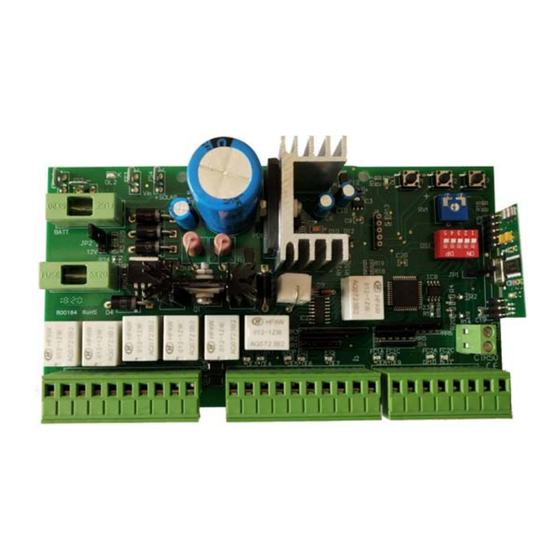
    (page 46), l’intervention du senseur ampérométrique avec RV1, et d’autres éventuelles personnalisations. L) BRANCHEMENT BATTERIE TAMPON Le tableau CTR50 peut être utilisé pour commander des moteurs à 24Vdc avec ou sans batterie tampon. Le chargeur de batterie est intégré sur la fiche.
  • Page 47 FRANCAIS Boutons de programmation AC IN électrique Batterie transformateur Led de programmation — Réseau Capteur ampérométrique 5 4 3 2 1 Fusible batterie 10A Dip switch Jumper JP2 Jumper JP1 Chargeur batterie Fusible Services 1A ANTENNE 1 2 3 4 5 6 7 8 9 10 1 2 3 4 5 6 7 8 9 10 1 2 3 4 5 6 7 8 SERRURE EL.

Table des Matières