Publicité

Les langues disponibles
  • FR

Les langues disponibles

Liens rapides

Istruzioni per l'uso e l'installazione
IT
Cappa
Instructions for use and installation
GB
Cooker Hood
Mode d'emploi et installation
FR
Hotte de Cuisine
Bedienungsanleitung und Einrichtung
DE
Dunstabzugshaube
Kullanım ve montaj talimatları
TR
Davlumbaz
FDF 6046
FDF 9046

Publicité

Table des Matières
loading

Sommaire des Matières pour Franke FDF 6046

  • Page 1 Istruzioni per l’uso e l’installazione Cappa Instructions for use and installation Cooker Hood Mode d’emploi et installation Hotte de Cuisine Bedienungsanleitung und Einrichtung Dunstabzugshaube Kullanım ve montaj talimatları Davlumbaz FDF 6046 FDF 9046...
  • Page 2: Table Des Matières

    Libretto di Istruzioni INDICE CONSIGLI E SUGGERIMENTI.............................. 7 CARATTERISTICHE................................8 INSTALLAZIONE..................................9 USO ......................................12 MANUTENZIONE.................................13...
  • Page 3 Instructions Manual INDEX RECOMMENDATIONS AND SUGGESTIONS........................14 CHARACTERISTICS................................15 INSTALLATION ..................................16 USE.......................................19 MAINTENANCE ...................................20...
  • Page 4 Manuel d’Instructions SOMMAIRE CONSEILS ET SUGGESTIONS ............................21 CARACTERISTIQUES.................................22 INSTALLATION ..................................23 UTILISATION..................................26 ENTRETIEN ..................................27...
  • Page 5 Bedienungsanleitung INHALTSVERZEICHNIS EMPFEHLUNGEN UND HINWEISE............................28 CHARAKTERISTIKEN .................................29 MONTAGE....................................30 BEDIENUNG ..................................33 WARTUNG ...................................34...
  • Page 6 Kullanim Kilavuku IÇERIKLER TAVSIYELER VE ÖNERILER..............................35 ÖZELLIKLER..................................36 MONTAJ....................................37 KULLANIM....................................40 BAKIM....................................41...
  • Page 7: Consigli E Suggerimenti

    CONSIGLI E SUGGERIMENTI INSTALLAZIONE • Il produttore declina qualsiasi responsabilità per danni dovuti ad installazione non corretta o non conforme alle regole dell’arte. • La distanza minima di sicurezza tra il Piano di cottura e la Cappa deve essere di 650 mm. •...
  • Page 8: Caratteristiche

    CARATTERISTICHE Ingombro 14.1 Componenti 12a 7.2.1 Rif. Q.tà Componenti di Prodotto Corpo Cappa completo di: Comandi, Luce, Gruppo Ventilatore, Filtri Camino Telescopico formato da: Camino Superiore Camino Inferiore Flangia di Riduzione ø 150-120 mm 14.1 Prolunga Raccordo Uscita Aria Raccordo Uscita Aria Rif.
  • Page 9: Installazione

    INSTALLAZIONE Foratura Parete e Fissaggio Staffe 7.2.1 Tracciare sulla Parete: • una linea Verticale fino al soffitto o al limite superiore, al centro della zona prevista per il montaggio della Cappa; • una linea Orizzontale a: 650 mm min. sopra il Piano di Cottura. •...
  • Page 10 Montaggio Corpo Cappa • Prima di agganciare il Corpo Cappa, serrare le 2 Viti Vr situate sui punti di aggancio del Corpo Cappa. • Agganciare il Corpo Cappa alle Viti 12a. • Serrare definitivamente le Viti 12a di supporto. • Agire sulle Viti Vr per livellare il Corpo Cappa. Connessioni USCITA ARIA VERSIONE ASPIRANTE ø...
  • Page 11 CONNESSIONE ELETTRICA • Collegare la Cappa all’Alimentazione di Rete inter- ponendo un Interruttore bipolare con apertura dei contatti di almeno 3 mm. • Rimuovere i Filtri antigrasso (vedi par. “Manuten- zione”) e assicurarsi che il connettore del Cavo di a- limentazione sia correttamente inserito nella presa dell’Aspiratore 7.2.1...
  • Page 12: Uso

    V1 V1 V1 V1 V1 V1 V1 V1 V1 V1 V1 V1 V1 V1 V1 V1 V1 V1 Luci Accende e spegne l’Impianto di Illuminazione. Led accensione Motore. Motore Accende e spegne il motore Aspirazione a velocità minima, adatta ad un ricambio d’aria continuo particolarmente silenzioso, in presenza di pochi vapori di cottura.
  • Page 13: Manutenzione

    MANUTENZIONE Filtri antigrasso PULIZIA FILTRI ANTIGRASSO METALLICI AUTOPORTANTI • Sono lavabili anche in lavastoviglie, e necessitano di essere lavati ogni 2 mesi circa di utilizzo o più frequentemente, per un uso particolarmente inten- • Togliere i Filtri uno alla volta, spingendoli verso la parte posteriore del gruppo e tirando contempora- neamente verso il basso.
  • Page 14: Recommendations And Suggestions

    RECOMMENDATIONS AND SUGGESTIONS INSTALLATION • The manufacturer will not be held liable for any damages resulting from incorrect or improper installation. • The minimum safety distance between the cooker top and the extrac- tor hood is 650 mm. • Check that the mains voltage corresponds to that indicated on the rating plate fixed to the inside of the hood.
  • Page 15: Characteristics

    CHARACTERISTICS Dimensions 14.1 Components 12a 7.2.1 Ref. Q.ty Product Components Hood Body, complete with: Controls, Light, Blower, Filters Telescopic Chimney comprising: Upper Section Lower Section Reducer Flange ø 150-120 mm 14.1 Air Outlet Connection Extension Air Outlet Connection Ref. Q.ty Installation Components 7.2.1 Upper Chimney Section Fixing Brackets Air Outlet Connection Support...
  • Page 16: Installation

    INSTALLATION Wall drilling and bracket fixing 7.2.1 Wall marking: • Draw a vertical line on the supporting wall up to the ceiling, or as high as practical, at the centre of the area in which the hood will be installed. •...
  • Page 17 Mounting the hood body • Before attaching the hood body, tighten the two screws Vr lo- cated on the hood body mounting points. • Hook the hood body onto the screws 12a. • Fully tighten support screws 12a. • Adjust screws Vr to level the hood body. Connections DUCTED VERSION AIR EXHAUST SYSTEM ø...
  • Page 18 ELECTRICAL CONNECTION • Connect the hood to the mains through a two-pole switch having a contact gap of at least 3 mm. • Remove the grease filters (see paragraph Mainte- nance) being sure that the connector of the feeding cable is correctly inserted in the socket placed on the side of the fan.
  • Page 19: Use

    V1 V1 V1 V1 V1 V1 V1 V1 V1 V1 V1 V1 V1 V1 V1 V1 V1 V1 Light Switches the lighting system on and off. Motor running led. Motor Switches the extractor motor on and off at low speed. Used to provide a contin-uos and silent air change in the presence of light cooking vapours.
  • Page 20: Maintenance

    MAINTENANCE Grease filters CLEANING METAL SELF- SUPPORTING GREASE FILTERS • The filters must be cleaned every 2 months of ope- ration, or more frequently for particularly heavy usage, and can be washed in a dishwasher. • Remove the filters one at a time by pushing them towards the back of the group and pulling down at the same time.
  • Page 21 CONSEILS ET SUGGESTIONS INSTALLATION • Le fabricant décline toute responsabilité en cas de dommage dû à une installation non correcte ou non conforme aux règles de l’art. • La distance minimale de sécurité entre le plan de cuisson et la hotte doit être de 650 mm au moins.
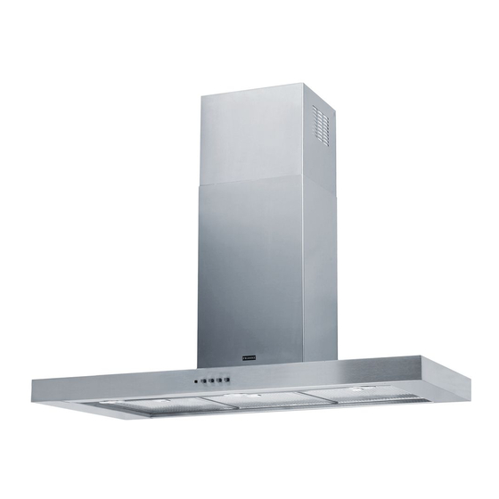
  • Page 22 CARACTERISTIQUES Encombrement 14.1 Composants 12a 7.2.1 Réf. Q.té Composants de Produit Corps Hotte équipé de:Comandes, Lumière,Groupe Ventilateur,Filtres Cheminée Télescopique formée de : Cheminée Supérieure Cheminée Inférieure Flasque de Réduction ø 150-120 mm 14.1 Rallonge Raccord Sortie Air Raccord Sortie Air Réf.
  • Page 23 INSTALLATION Perçage Paroi et Fixation Brides 7.2.1 Tracer sur la paroi: • une ligne verticale allant jusqu’au plafond ou à la limite supérieure, au centre de la zone prévue pour le montage de la hotte; • une ligne horizontale à 650 mm min. au-dessus du plan de cuisson. •...
  • Page 24 Montage Corps Hotte • Avant d’accrocher le corps hotte, serrer les deux vis Vr situées sur les points d’accrochage du corps hotte. • Accrocher le corps hotte aux vis 12a prévues à cet effet. • Serrer définitivement les vis 12a de support. •...
  • Page 25 BRANCHEMENT ELECTRIQUE • Brancher la hotte sur le secteur en interposant un in- terrupteur bipolaire avec ouverture des contacts d’au moins 3 mm. • Enlever les filtres à graisse (voir § "Entretien") et s'assurer que le connecteur du câble d'alimentation soit bien branché...
  • Page 26 UTILISATION V1 V1 V1 V1 V1 V1 V1 V1 V1 V1 V1 V1 V1 V1 V1 V1 V1 V1 Lumières Allume et éteint l’installation de l’éclairage. Del allumage Moteur. Moteur Met en marche et à l’arrêt le moteur aspiration à vitesse minimale, pour un rechange d’air permantent particulièrement silencieux en cas de faibles va- peurs de cuisson.
  • Page 27 ENTRETIEN Filtres anti-graisse NETTOYAGE FILTRES ANTI-GRAISSE METALLIQUES AUTOPORTEURS • Lavables au lave-vaisselle, ils doivent être lavés en- viron tous les 2 mois d’emploi ou plus fréquemment en cas d’emploi particulièrement intense. • Retirer les filtres l’un aprés l’autre, en les poussant vers la partie arrière du groupe et en tirant simulta- nément vers le bas.
  • Page 28 EMPFEHLUNGEN UND HINWEISE MONTAGE • Der Hersteller haftet nicht für Schäden, die auf eine fehlerhafte und unsachgemäße Montage zurückzuführen sind. • Der minimale Sicherheitsabstand zwischen Kochmulde und Haube muss 650 mm betragen. • Prüfen, ob die Netzspannung mit dem Wert auf dem im Haubeninne- ren angebrachten Schild übereinstimmt.
  • Page 29 CHARAKTERISTIKEN Platzbedarf 14.1 Komponenten 12a 7.2.1 Pos. Produktkomponenten Haubenkörper mit Schaltern,Beleuchtung, Gebläse- gruppe,Filter Teleskopkamin bestehend aus: oberer Kaminteil unterer Kaminteil Reduzierflansch ø 150-120 mm 14.1 Verlängerung Luftaustritt-Anschlussstück Luftaustritt-Anschlussstück Pos. Montagekomponenten 7.2.1 Befestigungsbügel oberer Kaminteil Bügel für Anschlusshalter Bügel Schrauben 4,2 x 44,4 Schrauben 2,9 x 9,5 Dokumentation Bedienungsanleitung...
  • Page 30 MONTAGE Bohren der Befestigungslöcher und Fixieren der Befestigungsbügel 7.2.1 Nachstehende Linien an die Wand zeichnen: • Eine vertikale Linie bis zur Decke oder oberen Begrenzung, und zwar in der Mitte des Berei- ches,in dem die Haube montiert werden soll; • Eine horizontale Linie: mit einem minimalen Abstand von 650 mm zur Kochfläche. •...
  • Page 31 Montage des Haubenkörpers • Bevor der Haubenkörper eingehakt wird, die 2 Schrauben Vr bei den Haubenkörper-Anhakpunkten festziehen. • Den Haubenkörper bei den Schrauben 12a einhängen. • Die Halteschrauben 12a definitiv festziehen. • Den Haubenkörper mit Hilfe der Schrauben Vr ausrichten. Anschlüss in abluftversion Bei Abluftbetrieb kann die Haube vom Installateur wahlweise ø...
  • Page 32 ELEKTROANSCHLUSS • Bei Anschluss der Haube an das Stromnetz muss ein zweipoliger Schalter mit einem Öffnungsweg von mindestens 3 mm zwischengeschaltet werden. • Entfernen Sie die Fettfilter (s. Abschnitt „Wartung“) und versichern Sie sich, daß die Kabelverbindung in die Steckdose des Gebläses einwandfrei eingesteckt wird.
  • Page 33 BEDIENUNG V1 V1 V1 V1 V1 V1 V1 V1 V1 V1 V1 V1 V1 V1 V1 V1 V1 V1 Beleucht. Schaltet die Beleuchtung ein und aus. Betriebsanzeigelampe. Motor Schaltet den Gebläsemotor mit minimaler Geschwindigkeit ein oder aus. Diese Stufe ist für einen ständigen und besonders leisen Luftaustausch bei geringer Kochdunstentwicklung geeignet.
  • Page 34 WARTUNG Fettfilter SELBSTTRAGENDER METALLFETTFILTER REINIGUNG • Sie müssen nach 2-monatigem Betrieb bzw. bei starkem Einsatz auch häufiger gereinigt werden, was im Geschirrspüler möglich ist. • Die Filter nacheinander aushaken, indem sie auf die Rückseite der Gruppe geschoben und glei- chzeitig nach unten gezogen werden. •...
  • Page 35 TAVSIYELER VE ÖNERILER MONTAJ • Yalnιş veya eksik montajdan doğan herhangi bir zararιn sorum- luluğu üreticiye ait değildir. • Davlumbaz ile pişirici cihazιn ocak kιsmι arasιndaki minimum güvenlik mesafesi 650 mm.dir. • Besleme voltajιnιn, davlumbaz içerisine yerleştirilen bilgi etike- tinde belirtilenle aynι olup olmadιğιnι kontrol edin. •...
  • Page 36 ÖZELLIKLER Boyutlar Parçalar 14.1 Ref. Adet Ürünün parçaları 12a 7.2.1 Şunlardan oluşan davlumbaz gövdesi: Kumandalar, Lamba, Fan grubu, Filtreler Şunlardan oluşan teleskopik baca: Üst baca Alt baca Redüksiyon Flanşı ø 150-120 mm 14.1 Hava Çıkışı Uzatma Rakoru Hava Çıkışı Rakoru Ref.
  • Page 37 MONTAJ Duvarın Delinmesi ve Braketlerin Sabitlenmesi 7.2.1 Duvara şunları çiziniz: • Tavana yada üst sınıra kadar uzunan Dikey bir çizgi: Davlumbazın monte edileceği yerin tam merkezinden geçmelidir; • Tezgâh (setüstü ocak) yüzeyinden 650 mm mesafeden geçen bir Yatay çizgi. • Gösterildiği gibi Braketi 7.2.1 tavandan 1-2 mesafeye dayayınız ve bunun merkezini (çen- tik) Dikey referans çizgisine hizalayınız.
  • Page 38 Davlumbaz Gövdesi Montajı • Davlumbaz Gövdesini kancalara takmadadan önce gövde üze- rindeki kancalama noktalarında bulunan 2 adet vidayı Vr sıkı- nız. • Davlumbaz Gövdesini vidalara 12a takınız. • Destek vidalarını 12a nihai olarak sıkınız. • Vr vidalarına müdahale ederek Davlumbaz Gövdesi seviyesini hizalayınız.
  • Page 39 ELEKTRİK BAĞLANTISI • Davlumbazı şebeke cereyanına bağlarken aray temas aralığı en az 3 mm olan çift kutuplu bir elektrik ana- htarı koyunuz. • Yağ tutucu filtreleri çıkarınız (bakınız "Bakım" para- grafı) ve besleme kablosu soketinin aspiratör prizine iyice takılmış olduğundan emin olunuz. 7.2.1 Bacanın Montajı...
  • Page 40 KULLANIM V1 V1 V1 V1 V1 V1 V1 V1 V1 V1 V1 V1 V1 V1 V1 V1 V1 V1 Lambalar Aydınlatma sistemini yakar ve söndürür Motorun çalışmakta olduğunu bildiren led lambası Motor Aspiaratör motorunu minimum hızda açar ve kapatır ; minimum hız sessi- zce çalışarak aşırı...
  • Page 41 BAKIM Yağ tutucu filtreler METALİK YAĞ TUTUCU FİLTRELERİN TEMİZLENMESİ • Bu filtreler bulaşık makinasında da yıkanabilir ve normal kullanıldıklarında iki ayda bir, yoğun kul- lanım halinde ise daha sıkça yıkanmalarıı gerekli- dir. • Filtrleri, grubun arka tarafından ittirerek ve aynı anda aşağı...
  • Page 44 çevre ve insan sağlığı üzerindeki olumsuz etkilerini bertaraf etmeye katkı sağlamış olursunuz. Bu ürünün geri dönüşüm koşulları hakkında daha ayrıntılı bilgi için hudutları içinde bulunduğunuz belediyenin ilgili diaresine, atık yoketme servisine veya ürünün satıcısına danışınız. Franke S.p.a. Via Pignolini,2 37019 Peschiera del Garda (VR) www.franke.it...

Ce manuel est également adapté pour:

Fdf 9046

Table des Matières