Datalogic SE-SR2 Manuel D'utilisation
Bloc logique de sécurité
Table des Matières
Liens rapides
21069-04
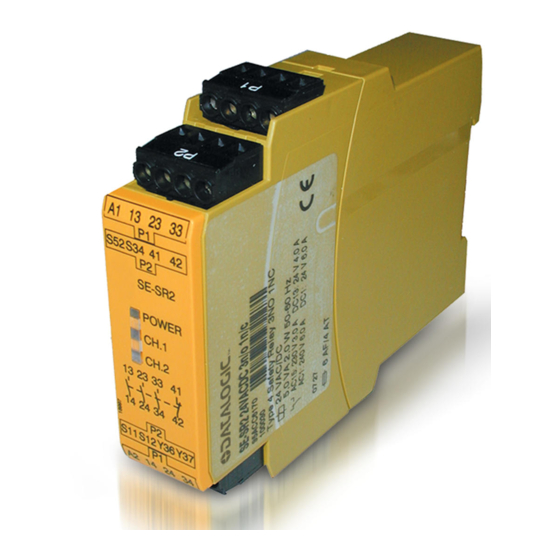
SE-SR2
Norme di sicurezza
• Il dispositivo può venire installato e
messo in funzione solo da tecnici elettrici
qualificati e competenti oppure da
personale istruito al riguardo e che siano
a conoscenza sia delle presenti istruzioni
per l'uso che delle norme vigenti riguardo
alla sicurezza del lavoro ed
antinfortunistica. Osservare le norme VDE
e quelle locali, specialmente per quanto
riguarda le misure preventive di
protezione.
• Durante il trasporto, l'immagazzinamento
e il funzionamento attenersi alle
condizioni prescritte dalla norma EN
60068-2-6 (v. Dati tecnici). Al termine
della propria durata, smaltire il dispositivo
in conformità alle norme vigenti.
• L'apertura della custodia o eventuali
modifiche apportate senza autorizzazioni,
comportano la perdita della garanzia.
• Assicurarsi che tutti i contatti di uscita per
carichi capacitivi e induttivi siano dotati di
un circuito protezione adeguato.
• La presente descrizione funge da
manuale di istruzioni e va conservata in
previsione di un futuro impiego.
Uso previsto
Il modulo di sicurezza è concepito per
essere utilizzato in
• circuiti di arresto di emergenza
• circuiti elettrici di sicurezza in conformità
alla norma EN 60204-1 (VDE 0113-1), ad
es. nelle barriere fotoelettriche
Descrizione
La tensione di alimentazione è di 24 V DC.
Caratteristiche:
• Uscite relè: 3 contatti di sicurezza (NA) e
un contatto ausiliario (NC) con contatti
guidati
• Possibilità di collegamento per, barriere
fotoelettriche (ESPE), pulsante di start
• Visualizzazione di stato
• Possibile controllo di relè esterni
• Nessuna separazione galvanica tra U
circuito di ingresso
Il dispositivo elettrico risponde ai seguenti
requisiti di sicurezza:
• Il circuito è strutturato in modo ridondante
con autocontrollo (EN 954-1, categoria 4).
• Il dispositivo mantiene la sua funzione di
sicurezza anche in caso di guasto di un
componente.
• La corretta apertura e chiusura dei relè di
sicurezza è verificata ad ogni ciclo on-off
del dispositivo.
Sicherheitsbestimmungen
• Das Gerät darf nur von einer Elektro-
fachkraft oder unterwiesenen Personen
installiert und in Betrieb genommen
werden, die mit dieser Betriebsanleitung
und den geltenden Vorschriften über
Arbeitssicherheit und Unfallverhütung
vertraut sind. Beachten Sie die VDE-
sowie die örtlichen Vorschriften, insbe-
sondere hinsichtlich Schutzmaßnahmen.
• Halten Sie beim Transport, der Lagerung
und im Betrieb die Bedingungen nach
EN 60068-2-6 ein (siehe technische
Daten). Entsorgen Sie das Gerät nach
Ablauf seiner Lebensdauer sachgerecht.
• Durch Öffnen des Gehäuses oder eigen-
mächtige Umbauten erlischt jegliche
Gewährleistung.
• Sorgen Sie an allen Ausgangskontakten
bei kapazitiven und induktiven Lasten für
eine ausreichende Schutzbeschaltung.
• Diese Betriebsanleitung dient der
Instruktion und ist für künftige Verwen-
dung aufzubewahren.
Bestimmungsgemäße Verwendung
Das Sicherheitsschaltgerät ist bestimmt für
den Einsatz in
• NOT-AUS-Einrichtungen
• Sicherheitsstromkreisen nach
EN 60204-1 (VDE 0113-1), z. B. bei
berührungslos wirkenden Schutzein-
richtungen
Gerätebeschreibung
Die Versorgungsspannung beträgt 24 V DC.
Merkmale:
• Relaisausgänge: 3 Sicherheitskontakte
(Schließer) und ein Hilfskontakt (Öffner),
zwangsgeführt
• Anschlussmöglichkeit für Lichtvorhang,
(BWS), Starttaster
• Statusanzeige
• Überwachung externer Schütze möglich
• keine galvanische Trennung zwischen U
e
B
und Eingangskreis
Das Schaltgerät erfüllt folgende Sicherheits-
anforderungen:
• Schaltung ist redundant mit Selbst-
überwachung aufgebaut (EN 954-1
Kategorie 4).
• Sicherheitseinrichtung bleibt auch bei
Ausfall eines Bauteils wirksam.
• Bei jedem Ein-Aus-Zyklus der Maschine
wird automatisch überprüft, ob die Relais
der Sicherheitseinrichtung richtig öffnen
und schließen.
• The unit may only be installed and
• Transport, storage and operating
• Any guarantee is rendered invalid if the
• Sufficient fuse protection must be
• These operating instructions should be
Intended application
The safety relay is designed for use in:
• E-STOP installations
• Safety circuits to EN 60204-1
Unit description
Supply voltage is 24 VDC.
Features:
• Relay outputs: 3 safety contacts
• Connection option for light curtain
• Status display
• Monitoring of external contactors possible
• No galvanic isolation between U
B
The relay conforms to the following safety
criteria:
• The circuit is redundant, with automatic
• The safety function remains effective
• The correct opening and closing of the
- 1 -
Safety regulations
commissioned by a competent, qualified
electrician or personnel instructed
accordingly, who is/are familiar with both
these operating instructions and the
current regulations for health and safety
at work and accident prevention. Follow
VDE and local regulations, especially as
regards preventative measures.
conditions should all conform to
EN 60068-2-6 (see "Technical details").
The unit must be disposed of properly
when it reaches the end of its service life.
housing is opened or unauthorised
modifications are carried out.
provided on all output contacts with
capacitive and inductive loads.
retained for future reference.
(VDE 0113-1), e.g. for electrosensitive
protective equipment
(N/O contacts) and an auxiliary contact
(N/C contact), positive guided
(ESPE), reset button
input circuit
built-in monitoring (EN 954-1, Category 4).
even in the case of a component failure.
safety function relays is tested automati-
cally in each on-off cycle.
and
B
Table des Matières

Manuels Connexes pour Datalogic SE-SR2


Sommaire des Matières pour Datalogic SE-SR2
- Page 1 21069-04 SE-SR2 Norme di sicurezza Sicherheitsbestimmungen Safety regulations • Il dispositivo può venire installato e • Das Gerät darf nur von einer Elektro- • The unit may only be installed and fachkraft oder unterwiesenen Personen messo in funzione solo da tecnici elettrici...
-
Page 2: Descrizione Del Funzionamento
Descrizione del funzionamento Funktionsbeschreibung Function description Il dispositivo assicura l'interruzione di Das Schaltgerät dient dem sicher- The relay provides a safety-related interrup- sicurezza di un circuito elettrico di heitsgerichteten Unterbrechen eines tion of a safety circuit. When the operating sicurezza. Dopo l’immissione della tensione Sicherheitsstromkreises. -
Page 3: Montage
Montaggio Montage Installation Il modulo di sicurezza deve essere montato Bauen Sie das Sicherheitsschaltgerät in The safety relay must be installed in a in un armadio elettrico con un tipo di einen Schaltschrank mit einer Schutzart von control cabinet with a minimum protection protezione corrispondente almeno al grado mindestens IP54 ein. - Page 4 Utilizzo Anwendung Application Da fig. 2 a fig. 5 sono rappresentati esempi di Fig. 2 bis Fig. 5 sind Anschlussbeispiele. Figs. 2 through 5 are connection examples. collegamento. Per la fig. 3 considerare che il Beachten Sie bei Fig. 3: Das Gerät startet Note for Fig.
- Page 5 Dati tecnici/Technische Daten/Technical details Tensione di alimentazione U /Versorgungsspannung U /Supply voltage U 24 V DC Tolleranza di tensione/Spannungstoleranz/Voltage tolerance -15 ... +10 % Potenza assorbita a U /Leistungsaufnahme bei U /Power consumption at U Ondulazione residua/Restwelligkeit/Residual ripple DC: 160 % Tensione e corrente su/Spannung und Strom an/Voltage and current at Circuito d’ingresso/Eingangskreis/Input circuit 24 V, 30 mA...
- Page 6 4,5 A Durata dei relè di uscita/Lebensdauer der Ausgangsrelais/Service life of output relays Dimensioni in mm (")/Abmessungen in mm (")/Dimensions in mm (") DATALOGIC S.p.A via Lavino 265, 40050 Monte San Pietro, Bologna Italy Tel. +39 051/6765611 Fax +39 051/6759324 www.Datalogic.com...
- Page 7 21069-04 SE-SR2 Prescripciones de seguridad Consignes de sécurité Veiligheidsvoorschriften • El dispositivo tiene que ser instalado y • Cet appareil ne doit être installé que par • Het apparaat mag uitsluitend worden puesto en funcionamiento exclusivamente un électricien ou une personne spéciali- geïnstalleerd en in bedrijf genomen door...
-
Page 8: Descripción Del Funcionamiento
Descripción del funcionamiento Description du fonctionnement Functiebeschrijving El dispositivo sirve para interrumpir un Le bloc logique sert à interrompre en toute Het relais dient om een veiligheidscircuit circuito de seguridad por razones de sécurité un circuit de sécurité. À la mise veilig te onderbreken. - Page 9 Montaje Montage Montage Monte el dispositivo en un armario de Installez le bloc logique de sécurité dans Bouw het veiligheidsrelais in een schakel- distribución con un grado de protección de une armoire ayant un indice de protection kast in met een beschermingsgraad van IP 54 como mínimo.
-
Page 10: Erreurs - Défaillances
Aplicación Utilisation Toepassing En la figura 2 hasta la figura 5 se muestran Les fig. 2 à 5 sont des exemples de raccorde- Afb. 2 t/m afb. 5 zijn aansluitvoorbeelden. ejemplos de conexión. Observe en la figura 3 ment. Respectez la fig. 3 : l’appareil démarre Opgelet bij afb. - Page 11 Datos técnicos/Caractéristiques techniques/Technische gegevens Tensión de alimentación U /Tension d’alimentation U /Voedingsspanning U 24 V DC Tolerancia de tensión/Plage de la tension d’alimentation/Spanningstolerantie -15 ... +10 % Consumo de energía con U /Consomation pour U /Opgenomen vermogen bij U Ondulación residual/Ondulation résiduelle/Rimpelspanning DC: 160 % Tensión y intensidad en/Tension et courant du/Spanning en stroom op el circuito de entrada/circuit d’entrée/ingangscircuit...
- Page 12 Vida útil de los relés de salida/Durée de vie du relais de sortie/Levensduur van de uitgangsrelais Dimensiones en mm (")/Dimensions en mm (")/Afmetingen in mm (") DATALOGIC S.p.A via Lavino 265, 40050 Monte San Pietro, Bologna Italy Tel. +39 051/6765611 Fax +39 051/6759324 www.Datalogic.com...
-
Page 13: Declaration Of Conformity
Conformity has been certified by the following Notified/Competent Body (identification n° 0123): TÜV S ÜD Rail GmbH, Ridlerstrasse, 65 – D80339 München Datalogic Automation have a quality system certified by the CSQ, Nr. 9115.IES2, as per ISO 9001 and have therefore observed the regulations foreseen during development and production... - Page 14 Notes - 8 -...
- Page 15 Notes - 9 -...
- Page 16 Notes DATALOGIC S.p.A via Lavino 265, 40050 Monte San Pietro, Bologna Italy Tel. +39 051/6765611 Fax +39 051/6759324 www.Datalogic.com - 10 -...