Publicité
Liens rapides
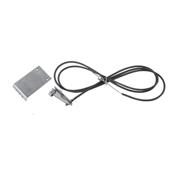
SBLOCCO ESTERNO CON CAVO / EXTERNAL RELEASE WITH CABLE / DÉBLOCAGE EXTÉRIEUR
AVEC CÂBLE / EXTERNE ENTRIEGELUNG MIT KABEL / DESBLOQUEO EXTERIOR CON CABLE
Per un corretto montaggio, procedere come segue:
I
1. Verificare il contenuto della confezione (vedi fig. 1);
2. forare con una punta diam. 3 mm il perno della maniglia della porta basculante (vedi fig. 2);
3. fissare la piastrina (1 fig. 3) sul carter del blocco serratura della porta basculante (2 fig. 3) tramite le viti stesse del carter;
4. asportare dal motoriduttore il gruppo di sblocco manuale (3 fig. 3) e fissare nella medesima posizione il dispositivo per lo sblocco
esterno (4 fig. 3);
5. passare il cavetto metallico attraverso l'apposita vite (5 fig. 3) sulla piastrina, dopo aver inserito la guaina nel capocorda (1 fig. 1);
6. regolare la lunghezza del cavo metallico fino ad azionare lo sblocco (girando la maniglia della porta basculante) e bloccarlo tramite
la vite (6 fig. 3);
7. ottimizzare la regolazione agendo sulla vite montata sulla piastrina (5 fig. 3) prima di fissare il relativo dado di bloccaggio (7 fig. 3).
NOTE:
• all'atto dell'installazione verificare il taglio della guaina (deve essere netto per evitare strozzature) prima dell'applicazione
del capocorda;
• evitare, nello stendere il cavo fino ad arrivare alla maniglia, di formare angoli retti o curvi (per evitare strozzature);
• ingrassare tutte le parti in movimento per facilitare il ritorno del cavo;
• eseguire un periodico controllo della funzionalità del meccanismo, eventualmente agire sui dadi di regolazione della
guaina.
To mount it correctly, proceed as follows:
GB
1. Check the contents of the pack (see fig. 1);
2. drill a hole in the pin of the door handle using a 3mm diam. bit (see fig. 2);
3. fix the plate (1 fig. 3) to the door lock guard (2 fig. 3) using the same screws as the door guard;
4.
remove the manual release from the gear motor (3 fig. 3) and fix the external release device in its place (4 fig. 3);
5. thread the metal cable through the relative screw (5 fig. 3) on the plate,
terminal (1 fig. 1);
6. adjust the length of the cable until the door is released (the door handle turns) and fix with the screw (6 fig. 3);
7. optimise travel of the door by adjusting the screw mounted on the plate (5 fig. 3) before fixing the relative lock nut (7 fig. 3).
NOTE:
•
on installation, check the cut of the sheath, which must be clean to avoid blocking, before applying the cable terminal;
•
to avoid blocking, avoid right angles or bends when extending the cable to the handle;
•
grease all moving parts to ease the return of the cable;
• from time to time, check that the mechanism is working correctly, if necessary act on the sheathing adjustment nuts.
Für die korrekte Montage wir folgt vorgehen:
D
1. Verpackungsinhalt prüfen (siehe Abb. 1);
2. Mit einem spitzen Gegenstand (Durchmesser 3mm) den Bügel des Handgriffs der Kipptür aufbohren (siehe Abb. 2);
3. Plättchen (1 Abb. 3) mit den Gehäuseschrauben selbst auf dem Gehäuse der Verriegelung des Kipptors (2 Abb. 3) anbringen;
4.
Die manuelle Entriegelung (3, Abb. 3) vom Getriebemotor entfernen und die Vorrichtung für die externe Entriegelung (4, Abb.
3) in derselben Stellung befestigen;
5. Metallfaden durch die eigens dafür bestimmte Schraube (5 Abb. 3) auf dem Plättchen führen,
Endverschluss gesteckt worden ist (1, Abb. 1);
6. Länge des Metallfadens so regulieren, dass die Entriegelung durch Drehen des Griffs betätigt werden kann und mit der
Schraube in dieser Position fixieren (6 Abb. 3);
7. Durch Einwirken auf die auf dem Plättchen montierte Schraube (5 Abb. 3) die Einstellung optimieren und danach die
Feststellmutter anziehen (7 Abb. 3).
ANMERKUNG:
•
im Augenblick der Installation, vor der Anbringung des Endverschlusses prüfen, wie der Mantel geschnitten ist (es
muss ein sauberer Schnitt sein, um Drosselungen zu vermeiden);
•
beim Verlegen des Seils bis zum Griff 90 Grad Winkel oder Biegungen vermeiden (um Drosselungen zu verhindern);
•
alle sich bewegenden Teile einfetten, um den Rückgang des Seils zu erleichtern;
• Die Funktionstüchtigkeit des Mechanismus regelmäßig überprüfen, ggf. die Verstellmuttern des Mantels betätigen.
Pour un montage correct, procéder de la façon suivante :
F
1. vérifier le contenu de l'emballage (voir fig. 1) ;
2. percer avec un foret diam. 3 mm l'axe de la poignée de la porte basculante (voir fig. 2) ;
3. fixer la platine (1 fig. 3) sur le carter du bloc serrure de la porte basculante (2 fig. 3) avec les vis du carter ;
4.
enlever du motoréducteur le groupe de déblocage manuel (3 fig. 3) et fixer dans la même position le dispositif pour le déblocage
TAU srl - Via Enrico Fermi, 43 - 36066 Sandrigo (VI) - Italy
Tel +39 0444 750190 - Fax +39 0444 750376
www.tauitalia.com
D-MNL0SESP 24-08-20 - Rev.03
150SESP
after the sheath has been introduced in the cable
nachdem der Mantel in den
Publicité

Sommaire des Matières pour tau 150SESP
- Page 1 150SESP TAU srl - Via Enrico Fermi, 43 - 36066 Sandrigo (VI) - Italy Tel +39 0444 750190 - Fax +39 0444 750376 www.tauitalia.com D-MNL0SESP 24-08-20 - Rev.03 SBLOCCO ESTERNO CON CAVO / EXTERNAL RELEASE WITH CABLE / DÉBLOCAGE EXTÉRIEUR AVEC CÂBLE / EXTERNE ENTRIEGELUNG MIT KABEL / DESBLOQUEO EXTERIOR CON CABLE...
- Page 2 extérieur (4 fig. 3); 5. passer le câble métallique à travers la vis prévue à cet effet (5 fig. 3) sur la platine, après avoir introduit la gaine dans la cosse (1 fig. 1); 6. régler la longueur du câble métallique de manière à actionner le déblocage (en tournant la poignée de la porte basculante) et le bloquer avec la vis (6 fig.