
Manuels Connexes pour Emotron CDN-40 Série


Sommaire des Matières pour Emotron CDN-40 Série
- Page 1 Emotron CDN Drive unit CDN40-xxx 0,75 ... 7.5 kW Montageanleitung Mounting Instructions Instructions de montage Instrucciones para el montaje Istruzioni per il montaggio...
- Page 3 Lesen Sie zuerst diese Anleitung, bevor Sie mit den Arbeiten beginnen! Beachten Sie die enthaltenen Sicherheitshinweise. Please read these instructions before you start working! Follow the enclosed safety instructions Veuillez lire attentivement cette documentation avant toute action! Les consignes de sécurité...
- Page 4 075 4 kW 5.5 7.5 kW CDN40-xxx CDN-COM-xxx CDN-COM-xxx CDN40-xxx CDN-WU-xxx CDN-WU-xxx CDN40-xxx, DE/EN/FR/ES/IT...
-
Page 5: Table Des Matières
Inhalt Über diese Dokumentation ....................4 Dokumenthistorie ..................4 Zielgruppe ..........Informationen zur Gültigkeit . -
Page 6: Über Diese Dokumentation
DE/EN/FR/ES/IT (nur PDF) 01-6463-11 Tipp! Informationen und Hilfsmittel rund um die CGProdukte finden Sie im Download−Bereich(Fielarchive) unter http://www.emotron.com Zielgruppe Diese Dokumentation richtet sich an qualifiziertes Fachpersonal nach IEC 60364. Qualifiziertes Fachpersonal sind Personen, die für die auszuführenden Tätigkei- ten bei der Aufstellung, Montage, Inbetriebsetzung und dem Betrieb des Pro- dukts über entsprechende Qualifikationen verfügen. -
Page 7: Informationen Zur Gültigkeit
Über diese Dokumentation Informationen zur Gültigkeit Informationen zur Gültigkeit Diese Anleitung ist gültig für Antriebsregler Emotron CDN mit der Typenbe- zeichnung: Typenbezeichnung ab HW ab SW CDN40-xxx 01.00 Weitere Informationen zum Typenschlüssel enthält das Kapitel Produktbe- schreibung. Verwendete Konventionen Diese Dokumentation verwendet folgende Konventionen zur Unterscheidung... -
Page 8: Verwendete Hinweise
Über diese Dokumentation Verwendete Hinweise Verwendete Hinweise Um auf Gefahren und wichtige Informationen hinzuweisen, werden in dieser Dokumentation folgende Piktogramme und Signalwörter verwendet: Sicherheitshinweise Aufbau der Sicherheitshinweise: Gefahr! (kennzeichnet die Art und die Schwere der Gefahr) Hinweistext (beschreibt die Gefahr und gibt Hinweise, wie sie vermieden werden kann) Piktogramm und Signalwort Bedeutung... - Page 9 Über diese Dokumentation Verwendete Hinweise Spezielle Sicherheitshinweise und Anwendungshinweise Piktogramm und Signalwort Bedeutung Sicherheitshinweis oder Anwendungshinweis für den Warnings! Betrieb nach UL− oder CSA−Anforderungen. Die Maßnahmen sind erforderlich, um die Anforderun- gen nach UL oder CSA zu erfüllen. Warnings! CDN40-xxx, DE/EN/FR/ES/IT...
-
Page 10: Sicherheitshinweise
Sicherheitshinweise Sicherheitshinweise Gefahr! Gefährliche elektrische Spannung Die Leistungsanschlüsse führen bis zu 3 Minuten nach Netz−Ausschalten gefährliche elektrische Spannung. Mögliche Folgen: Tod oder schwere Verletzungen beim Berühren der Leistungsanschlüsse. Schutzmaßnahmen: Vor Arbeiten am Gerät Netzspannung ausschalten Warnung durch Symbole und mindestens 3 Minuten warten. - Page 11 Sicherheitshinweise Original − Englisch Warnings! These devices are suitable for field wiring. Intended for use with 75 °C wire. Intended for use with copper conductors only. Suitable for use in a surrounding air temperature of 45 °C, and ...
- Page 12 Sicherheitshinweise Original − Französisch Avertissements ! Ces équipements sont adaptés à un câblage à pied d’oeuvre. Utiliser des conducteurs 75 °C. Utiliser exclusivement des conducteurs en cuivre. Convient à une utilisation à une température ambiante maximale de 45 °C ainsi que 60 °C en cas d’application des règles de réduction de puissance.
-
Page 13: Technische Daten
Technische Daten Allgemeine Daten und Einsatzbedingungen Technische Daten Allgemeine Daten und Einsatzbedingungen Konformität und Approbation Konformität 2006/95/EG Niederspannungsrichlinie Über die Sicherheit Eurasische Konformität von Niederspannungs- (TR ZU 004/2011) TR ZU: Technische Regulie- ausrüstung rung der Zollunion Elektromagnetische Eurasische Konformität Verträglichkeit von (TR ZU 020/2011) TR ZU: Technische Regulie- technischen Erzeugnis-... - Page 14 Technische Daten Allgemeine Daten und Einsatzbedingungen Personenschutz und Geräteschutz EN 60529 IP65 im betriebsfertigen Schutzart Zustand: Nicht benutzte • Bohrungen für Kabelver- schraubungen mit Blind- stopfen verschließen! NEMA 250 Schutz nach Nicht benutzte Steck- • Typ 4 • verbinder mit Schutzkap- pen oder Blindsteckern verschließen! (Erd−) Ableitstrom...
- Page 15 Technische Daten Allgemeine Daten und Einsatzbedingungen Anschlussbedingungen Netzanschluss Netzsystem TT, TN Betrieb uneingeschränkt erlaubt. (mit geerdetem Sternpunkt) Die für IT−Netze beschriebene Maßnahme anwenden (IT−Schraube entfernen). Die Einhaltung der EMV−Anforderungen für die Störaussendung (EN 61800−3) für die Maschine/ Anlage liegt in der Verantwortung des Maschinen−/ Anlagenherstellers! Der Betrieb mit integrierter Sicherheitstechnik ist nicht zulässig.
- Page 16 Technische Daten Allgemeine Daten und Einsatzbedingungen Montagebedingungen Einbauort Standard Motormontage Steuerung Steuerungsverfahren VFCplus: • U/f−Steuerung (linear oder quadratisch) SLVC: • Sensorlose Vectorregelung (Drehzahl) VFCplus eco: • U/f−Steuerung, energetisch optimiert SLPSM: • Sensorlose Regelung für Synchronmotoren Schaltfrequenz 4 kHz CDN40-xxx, DE/EN/FR/ES/IT...
-
Page 17: Bemessungsdaten
Technische Daten Bemessungsdaten Bemessungsdaten Eingangsdaten Grundlage der Daten Netz Spannung Spannungsbereich Frequenzbereich f [Hz] 3/PE AC 320 − 0 % ... 440 + 0 % 45 − 0 % ... 65 + 0 % 3/PE AC 432 − 0 % ... 528 + 0 % 45 −... -
Page 18: Mechanische Installation
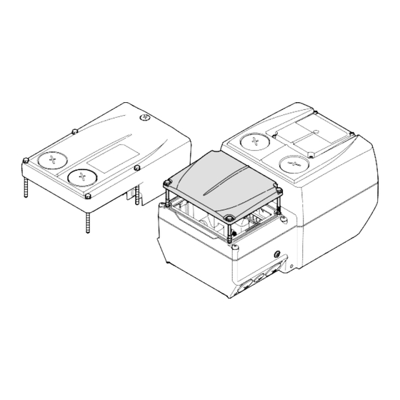
Mechanische Installation Montage Mechanische Installation Vorbereitung Die Montage und Verdrahtung der Wiring Unit und Communication Unit entsprechend der Montageanleitungen muss abgeschlossen sein. Montage 0.75 ... 4 kW Setzen Sie die Drive Unit −ohne zu verkanten− auf die vorher montierte Commu- nication Unit auf. - Page 19 Mechanische Installation Montage 5.5 ... 7.5 kW Die Drive Unit wurde bereits mit der Wiring Unit montiert. So schließen Sie die Montage ab: 1. Die klappbare Buchsenleiste zur CU drehen und vorsichtig in den Gegenstecker drücken. 2. Deckel der DU auf die Communication Unit setzen und 3.
-
Page 20: Parametrierung
Parametrierung Durch Parametrierung können Sie den Antriebsregler auf verschiedene Anforde- rungen von Anwendungen optimal einstellen. Die Parametrierung kann auf folgende Arten erfolgen: Parametrierung mit L−force » Emotron Easy Starter PC-tool « Umfangreiche Einstellungen Online per Software – Erfordert Software und USB−Diagnoseadapter ... -
Page 21: Einstellungen
Einstellungen Einstellungen Einstellelemente 0.75 ... 4 kW Auf der Innenseite der Drive Unit finden Sie die Einstellelemente. 0.75 ... 4 kW Bezeichnung Einstellung "Top Cover: Speed ... %" Anschluss für USB−Diagnoseadapter LED−Statusanzeige CDN40-xxx, DE/EN/FR/ES/IT... - Page 22 Einstellungen Einstellelemente 5.5 ... 7.5 kW Auf der Oberseite der Drive Unit finden Sie die Einstellelemente. Spannungsfreiheit sicherstellen und gegen Wiedereinschalten sichern. Kleinen Deckel auf der Oberseite abnehmen. 5.5 ... 7.5 kW Bezeichnung Einstellung "Top Cover: Speed ... %" Anschluss für USB−Diagnoseadapter ...
-
Page 23: Grundeinstellungen
Einstellungen Grundeinstellungen Einstellmöglichkeiten mit P1 Das Potentiometer P1 wird zugänglich nach entfernen des Verschlussdeckels. Um den Schutzgrad des Antriebsreglers zu gewährleisten, muss der Verschluss- deckel nach den Einstellungen wieder eingeschraubt werden. Während des Betriebes kann mit P1 stufenlos die Motordrehzahl in Prozent der Nenndrehzahl in C00011 eingestellt werden, sofern kein JOG−Festsollwert P2 über DI1 aktiv ist. - Page 24 Einstellungen Maßnahme bei Einsatz in IT−Netzen 5.5 ...7.5 kW CDN40-xxx, DE/EN/FR/ES/IT...
-
Page 25: Inbetriebnahme
Einstellungen Inbetriebnahme Inbetriebnahme Voraussetzungenfür das erste Einschalten Die Wiring Unit ist gemäß Anleitung montiert und verdrahtet, - direkt auf einem Motorklemmflansch oder mit dem Wandadapter auf einer geeigneten Fläche nahe des Motors. Anschlüsse mit Netz, Motor usw. sind hergestellt. ... - Page 26 Inbetriebnahme Inbetriebnahme Gehen Sie Schrittweise vor: Netz einschalten Statusanzeige beobachten Nach kurzer Initialisierungszeit muss die Anzeige grün blinken. Reglerfreigabe setzen Der Motor muss nach der eingestellten Anlaufzeit mit der eingestellten Geschwindigkeit drehen. Erste Prüfung des erwartungsgemäßen Verhaltens: ...
- Page 27 0.75 4 kW 5.5 7.5 kW CDN40-xxx CDN-COM-xxx CDN-COM-xxx CDN40-xxx CDN-WU-xxx CDN-WU-xxx CDN40-xxx, DE/EN/FR/ES/IT...
- Page 28 CDN40-xxx, DE/EN/FR/ES/IT...
- Page 29 Contents About this documentation ..................28 Document history ......... . Target group .
-
Page 30: About This Documentation
Tip! Information and auxiliary devices related to the CG products can be found in the download area at http://www.emotron.com Target group This documentation is directed at qualified skilled personnel according to IEC 60364. Qualified skilled personnel are persons who have the required qualifications to carry out all activities involved in installing, mounting, commissioning, and operating the product. -
Page 31: Validity Information
About this documentation Validity information Validity information These instructions are valid for Emotron CDN controllers with the following type designation: Type designation From HW From SW CDN40-xxx 01.00 Further information on the type code can be obtained from the "Product description"... -
Page 32: Notes Used
About this documentation Notes used Notes used The following pictographs and signal words are used in this documentation to indicate dangers and important information: Safety instructions Structure of safety instructions: Danger! (characterises the type and severity of danger) Note (describes the danger and gives information about how to prevent dangerous situations) Pictograph and signal word... - Page 33 About this documentation Notes used Special safety instructions and application notes Pictograph and signal word Meaning Safety note or application note for the operation Warnings! according to UL or CSA requirements. The measures are required to meet the requirements according to UL or CSA.
-
Page 34: Safety Instructions
Safety instructions Safety instructions Danger! Dangerous voltage The power terminals carry dangerous voltages for up to 3 minutes after mains disconnection. Possible consequences: Death or severe injury if the power terminals are touched. Protective measures: Switch off the mains voltage and wait at least 3 minutes before ... - Page 35 Safety instructions Original − English Warnings! These devices are suitable for field wiring. Intended for use with 75 °C wire. Intended for use with copper conductors only. Suitable for use in a surrounding air temperature of 45 °C, and ...
- Page 36 Safety instructions Original − French Avertissements ! Ces équipements sont adaptés à un câblage à pied d’oeuvre. Utiliser des conducteurs 75 °C. Utiliser exclusivement des conducteurs en cuivre. Convient à une utilisation à une température ambiante ...
-
Page 37: Technical Data
Technical data General data and operating conditions Technical data General data and operating conditions Conformity and approval Conformity 2006/95/EC LowVoltage Directive On safety of low Eurasian Conformity voltage equipment (TR CU 004/2011) TR CU: Technical Regulation of Customs Union Electromagnetic Eurasian Conformity compatibility of (TR CU 020/2011) - Page 38 Technical data General data and operating conditions Protection of persons and equipment in ready−for−use state: EN 60529 IP65 Enclosure optional: IP66 Close unused bores for • cable glands with blanking plugs! NEMA 250 Protection according to Close unused connectors • Type 4 •...
- Page 39 Technical data General data and operating conditions Supply conditions Mains connection Power system TT, TN Operation permitted without restrictions. (with an earthed neutral) Implement the measure described for IT systems (remove IT screw). The machine/system manufacturer is responsible for compliance with EMC requirements for noise emission (EN 61800−3) for the machine/plant! Operation with an integrated safety system is not permissible.
- Page 40 Technical data General data and operating conditions Mounting conditions Mounting place Standard Motor mounting Control Control modes VFCplus: V/f control (linear or square−law) • SLVC: Sensorless vector control (speed) • VFCplus eco: Energy−efficient V/f control • SLPSM • Sensorless control for Synchronous motors Switching frequency 4 kHz CDN40-xxx, DE/EN/FR/ES/IT...
-
Page 41: Rated Data
Technical data Rated data Rated data Input data Basis of the data Mains Voltage Voltage range Frequency range f [Hz] Lrated Lrated 3/PE AC 320 − 0 % ... 440 + 0 % 45 − 0 % ... 65 + 0 % 3/PE AC 432 −... -
Page 42: Mechanical Installation
Mechanical installation Mounting Mechanical installation Preparation Mounting and wiring of the wiring unit and communication unit must be completed in accordance with the mounting instructions Mounting 0.37 ... 3 kW Position the drive unit exactly onto the previously mounted communication unit. Fasten the drive unit with the four provided screws (torque: 5.0 Nm/44 lb−in). - Page 43 Mechanical installation 5.5 ... 7.5 kW The drive unit has already been mounted with the wiring unit. How to complete the mounting procedure: 1. Turn the hinged socket connector towards the CU and carefully insert it into the counter plug. 2.
-
Page 44: Parameter Setting
Parameter setting Parameterisation serves to adjust the controller optimally to different application requirements. Parameters can be set as follows: Parameter settings are performed by using >>Emotron Easy Starter PC-tool<< Extensive settings via software – Requires software and USB diagnostic adapter ... -
Page 45: Settings
Settings Settings Setting drives 0.75 ... 4 kW The setting/connection is done below the black screw cap, see picture below. 0.75 ... 4 kW Name Setting "Top Cover: Speed ... %" Connection for USB PC adapter LED status display CDN40-xxx, DE/EN/FR/ES/IT... - Page 46 Settings Setting elements 5.5 ... 7.5 kW The setting elements are located on the top of the drive unit. Provide for isolation from supply and secure to prevent a restart. Remove small cover on the top. 5.5 ... 7.5 kW Name Setting "Top Cover: Speed ...
-
Page 47: Basic Settings
Settings Basic settings Possible settings with P1 Potentiometer P1 can be accessed after the cover has been removed. In order to ensure the degree of protection of the controller, the cover has to be screwed in again after the settings have been made. - Page 48 Settings Measures when drive is used in IT systems 5.5 ...7.5 kW CDN40-xxx, DE/EN/FR/ES/IT...
-
Page 49: Commissioning
Commissioning Commissioning Preconditions for initial switch−on The wiring unit is mounted and wired according to the instructions, - directly on a motor clamping flange or with the wall adapter on a suitable surface near the motor. Connections with the mains, motor, etc. have been established. ... - Page 50 Commissioning Commissioning Commissioning Proceed step by step: Switch on the mains Observe status display After a short initialisation time, the display must be blinking green. Set controller enable After the set starting time, the motor must rotate with the set speed. First check of the expected behaviour: ...
- Page 51 0.75 4 kW 5.5 7.5 kW CDN40-xxx CDN-COM-xxx CDN-COM-xxx CDN40-xxx CDN-WU-xxx CDN-WU-xxx CDN40-xxx, DE/EN/FR/ES/IT...
- Page 52 CDN40-xxx, DE/EN/FR/ES/IT...
- Page 53 Présentation du document ......... Historique du document ................
-
Page 54: Présentation Du Document
01-6463-11 Conseil ! Toutes les informations relatives aux produits CG peuvent être téléchargées sur notre site à l’adresse suivante : http://www.emotron.com Public visé Cette documentation s’adresse à un personnel qualifié et habilité conformément à la norme CEI 60364. On entend par "personnel qualifié et habilité" des personnes compétentes en matière d’installation, de montage, de mise en service et de fonctionnement du... -
Page 55: Validité
Présentation du document Consignes utilisées Validité Le présent document s’applique aux variateurs de vitesse Emotron CDN suivants : Référence de commande A partir de la version matérielle A partir de la version logicielle (HW) (SW) CDN40-xxx 01.00 Pour plus d’informations sur la codification des types, consulter le chapitre Description du produit. - Page 56 Présentation du document Validité Consignes utilisées Pour indiquer des risques et des informations importantes, la présente documentation utilise les mots et pictogrammes suivants : Consignes de sécurité Présentation des consignes de sécurité Danger ! (Le pictogramme indique le type de risque.) Explication (L’explication décrit le risque et les moyens de l’éviter.) Pictogramme et mot associé...
- Page 57 Présentation du document Consignes de sécurité et d’utilisation spéciales Pictogramme et mot associé Description Consigne de sécurité ou d’utilisation pour le Avertissements ! fonctionnement selon les normes UL ou CSA. Les mesures sont requises pour répondre aux exigences des normes UL ou CSA.
-
Page 58: Consignesde Sécurité
Consignes de sécurité Consignes de sécurité Danger ! Tension électrique dangereuse Les raccordements de puissance sont susceptibles de véhiculer une tension dangereuse jusqu’à 3 minutes après une coupure réseau. Risques encourus : Mort ou blessures graves en cas de contact ... - Page 59 Consignes de sécurité Consignes de sécurité Original − Anglais Warnings! These devices are suitable for field wiring. Intended for use with 75 °C wire. Intended for use with copper conductors only. Suitable for use in a surrounding air temperature of 45 °C, and ...
- Page 60 Consignes de sécurité Original − French Avertissements ! Ces équipements sont adaptés à un câblage à pied d’oeuvre. Utiliser des conducteurs 75 °C. Utiliser exclusivement des conducteurs en cuivre. Convient à une utilisation à une température ambiante ...
-
Page 61: Spécifications Techniques
Spécifications techniques Spécifications techniques Caractéristiques générales et conditions d’utilisation Conformité et homologation Conformité 2006/95/CE Directive Basse Tension Sécurité des Conformité eurasienne équipements à basse RT UD : Règlement (RT UD 004/2011) tension technique de l’Union Douanière Compatibilité Conformité eurasienne électromagnétique des RT UD : Règlement (RT UD 020/2011) équipements... - Page 62 Spécifications techniques Caractéristiques générales et conditions d’utilisation Protection des personnes et protection de l’appareil A l’état prêt à fonctionner : EN 60529 IP65 Indice de protection En option : IP66 Les trous inutilisés • destinés aux presse−étoupes à vis doivent être obturés par des tampons borgnes ! NEMA 250 Protection selon...
- Page 63 Spécifications techniques Caractéristiques générales et conditions d’utilisation Protection des personnes et protection de l’appareil Protection contre les EN 61800−5−1 Raccordement : défauts de mise à la Moteur (au déblocage Protection conditionnée. Le terre variateur) variateur est bloqué. Un acquittement de défaut est nécessaire.
- Page 64 Spécifications techniques Caractéristiques générales et conditions d’utilisation Conditions ambiantes Conditions climatiques CEI/EN 60721−3−1 1K3 (−30 ... +60 °C) Stockage CEI/EN 60721−3−2 2K3 (−30 ... +75 °C) Transport CEI/EN 60721−3−3 Normal Duty: Fonctionnement 3K3 (−30 ... +40 °C) Fonctionnement avec 4 kH. Heavy Duty: 3K3 (-30 ...
- Page 65 Spécifications techniques Caractéristiques générales et conditions d’utilisation Commande VFCplus : Mode de commande pilotage en U/f (linéaire ou quadratique) • SLVC : régulation vectorielle sans bouclage (vitesse) • VFCplus eco: pilotage en U/f énergie efficace • SLPSM: • Commande sans capteur pour moteurs synchrones Fréquence de découpage 4 kHz CDN40-xxx, DE/EN/FR/ES/IT...
-
Page 66: Caractéristiques Assignées
Spécifications techniques Caractéristiques générales et conditions Caractéristiques assignées Données d’entrée Données de base Réseau Tension Plage de tension Plage de fréquence f [Hz] 3/PE CA 320 − 0 % ... 440 + 0 % 45 − 0 % ... 65 + 0 % 3/PE CA 432 −... -
Page 67: Installation Mécanique
Installation mécanique Montage Installation mécanique Préparation Le montage et le câblage du module de câblage (Wiring Unit) et du module de communication (Communication Unit) conformément aux instructions de montage doivent être achevés. Montage 0.75 ... 4 kW Positionner l’appareil de base (Drive Unit) sans le coincer sur le module de communication (Communication Unit) déjà... - Page 68 Installation mécanique Montage 5.5 ... 7.5 kW Le module de base (Drive Unit) a été monté avec le module de câblage (Wiring Unit). Pour terminer le montage : 1. Saisir le connecteur femelle côté CU et l’enficher délicatement dans la prise prévue à...
-
Page 69: Paramétrage
Le paramétrage permet d’adapter le variateur de vitesse de manière optimale aux exigences spécifiques de l’application. Il peut être réalisé de différentes manières : Paramétrage à l’aide du logiciel L−force » Emotron Easy Starter PC-tool « Réglages complexes via logiciel en mode en ligne ƒ... -
Page 70: Réglages
Réglages Réglages Eléments de réglage 0.75 ... 4 kW Les éléments de réglage se situent à l’intérieur de l’appareil de base (Drive Unit). 0.75 ... 4 kW Désignation Réglage "Top Cover: Speed ... %" Raccordement pour adaptateur de diagnostic USB ... - Page 71 Réglages Eléments de réglage 4 ... 7.5 kW Les éléments de réglage se situent sur la face avant du module de base (Drive Unit). S’assurer que la tension est coupée et qu’aucune mise sous tension impromptue n’est possible. Oter le petit couvercle sur la face avant. 5.5 ...
-
Page 72: Réglages De Base
Réglages Réglages de base Réglages possibles via P1 Retirer le couvercle pour accéder au potentiomètre P1. Après les réglages, revisser le couvercle afin de garantir l’indice de protection du variateur. Pendant le fonctionnement, la vitesse moteur peut être réglée en continu en pourcentage de la vitesse nominale réglée en C00011 à... - Page 73 Réglages Mesure à prévoir lors de l’utilisation dans des réseaux IT 5.5 ...7.5 kW CDN40-xxx, DE/EN/FR/ES/IT...
-
Page 74: Mise En Service
Mise en service Mise en service Conditions préalables de la première mise sous tension Le module de câblage (Wiring Unit) est monté et câblé selon les indications fournies, soit - directement sur la bride de serrage moteur ou, - avec un adaptateur mural, sur une surface appropriée en proximité du moteur. - Page 75 Mise en service Mise en service Procéder étape par étape : Mettre l’appareil sous tension. Observer l’affichage d’état. - Après un temps d’initialisation minimum, l’affichage vert doit clignoter. Activer le déblocage variateur. - Après expiration du temps de démarrage réglé, le moteur doit tourner à...
- Page 76 Mise en service 0.75 4 kW 5.5 7.5 kW CDN40-xxx CDN-COM-xxx CDN-COM-xxx CDN40-xxx CDN-WU-xxx CDN-WU-xxx CDN40-xxx, DE/EN/FR/ES/IT...
- Page 77 Contenido Acerca de esta documentación ........Historia del documento .
-
Page 78: Acerca De Esta Documentación
DE/EN/FR/ES/IT (sólo PDF) 01-6463-11 ¡Sugerencia! Encontrará información y recursos sobre los productos de Emotron en el área de descargas de http://www.emotron.com Grupo objetivo Esta documentación va dirigida a personal experto y cualificado según IEC 60364. Personal experto cualificado son aquellas personas que disponen de las cualificaciones adecuadas para realizar los trabajos necesarios para la instalación, montaje, puesta en marcha y operación del producto. -
Page 79: Información Sobre La Validez
Contenido Acerca de esta documentación Información sobre la validez Información sobre la validez Estas instrucciones son válidas para convertidores Emotron CDN con la denominación de tipo: Denominación de tipo a partir de la versión de a partir de la versión de... -
Page 80: Indicaciones Utilizadas
Acerca de esta documentación Indicaciones utilizadas Para indicar peligros e información importante, se utilizan en esta documentación los siguientes términos indicativos y símbolos: Instrucciones de seguridad Estructura de las instrucciones de seguridad: ¡Peligro! (indican el tipo y la gravedad del peligro) Texto indicativo (describe el peligro y da instrucciones para evitarlo) Pictograma y término indicativo... -
Page 81: Instrucciones De Seguridad
Instrucciones de seguridad Instrucciones de seguridad ¡Peligro! Voltaje eléctrico peligroso Las conexiones de potencia siguen vivas hasta 3 minutos después de la desconexión de red. Posibles consecuencias: Muerte o serias lesiones al tocar las conexiones de potencia. Medidas de protección: Antes de trabajar en el equipo, desconectar la alimentación ... - Page 82 Instrucciones de seguridad Instrucciones de seguridad Original − Inglés Warnings! These devices are suitable for field wiring. Intended for use with 75 °C wire. Intended for use with copper conductors only. Suitable for use in a surrounding air temperature of 45 °C, and ...
- Page 83 Instrucciones de seguridad Original − French Avertissements ! Ces équipements sont adaptés à un câblage à pied d’oeuvre. Utiliser des conducteurs 75 °C. Utiliser exclusivement des conducteurs en cuivre. Convient à une utilisation à une température ambiante ...
-
Page 84: Datos Técnicos
Datos técnicos Datos generales y condiciones de uso Datos técnicos Datos generales y condiciones de uso Conformidad y aprobaciones Conformidad 2006/95/CE Directiva de bajo voltaje Acerca de la seguridad Conformidad Eurasiática de equipos de bajo TR TS: Reglamento Técnico (TR TS 004/2011) voltaje de la Unión Aduanera Compatibilidad... - Page 85 Datos técnicos Datos generales y condiciones de uso Protección personal y de equipos EN 60529 IP65 En estado listo para Tipo de protección funcionar: opcional: IP66 ¡Cerrar los taladros para • prensaestopas que no se utilicen con tapones ciegos! NEMA 250 Protección según ¡Cerrar conectores •...
- Page 86 Datos técnicos Datos generales y condiciones de uso Protección personal y de equipos EN 61800−5−1 Resistencia al Conexión: contacto a tierra Motor (con convertidor condicionada, el convertidor habilitado) es inhibido, es necesario cancelar el error Motor (en funcionamiento) Resistencia de frenado, Corriente de conexión 2 x I Condiciones para la conexión...
- Page 87 Datos técnicos Datos generales y condiciones de uso Condiciones ambientales Climática IEC/EN 60721−3−1 1K3 (−30 ... +60 °C) Almacenaje IEC/EN 60721−3−2 2K3 (−30 ... +75 °C) Transporte IEC/EN 60721−3−3 Normal Duty: Funcionamiento 3K3 (−30 ... +40 °C) Funcionamiento con 4 kH. Heavy Duty: 3K3 (-30 ...
-
Page 88: Datos Nominales
Datos técnicos Datos nominales Datos nominales Datos de entrada Base de los datos Voltaje Rango de voltaje Rango de frecuencia f [Hz] 3/PE AC 320 − 0 % ... 440 + 0 % 45 − 0 % ... 65 + 0 % 3/PE AC 432 −... -
Page 89: Instalación Mecánica
Instalación mecánica Montaje Instalación mecánica Preparación El montaje y cableado de la unidad de cableado y la unidad de comunicación tiene que haberse realizado según las indicaciones de las instrucciones para el montaje. Montaje 0.75 ... 4 kW Coloque la unidad de accionamiento, sin que se ladee, sobre la unidad de comunicación que se ha montado primero. - Page 90 Instalación mecánica Montaje 5.5 ... 7.5 kW La Drive Unit (unidad de accionamiento) ya ha sido montada con la Wiring Unit (unidad de cableado). Para finalizar el montaje, proceda de la siguiente manera: 1. Girar la regleta de conectores hembra hacia la Communication Unit (unidad de comunicación) e insertarla con cuidado en el conector macho.
-
Page 91: Parametrización
Parametrización Parametrización Mediante la parametrización el convertidor se puede configurar de forma óptima para las distintas exigencias de las aplicaciones. La parametrización se puede realizar de las siguientes maneras: Parametrización con el L−force »Engineer« Amplias configuraciones online a través de software –... -
Page 92: Configuraciones
Configuraciones Configuraciones Elementos de configuración 0.75 ... 4 kW En el lado interior de la unidad de accionamiento se encuentran los elementos de configuración. 0.75 ... 4 kW Denominación Configuración "Top Cover: Speed ... %" Conexión para adaptador de diagnóstico USB ... - Page 93 Configuraciones Elementos de configuración 5.5 ... 7.5 kW En la parte superior de la Drive Unit (unidad de accionamiento), se encuentran los elementos de configuración. Confirmar que esté libre de tensión y asegurar contra el encendido involuntario. Retirar la pequeña tapa de la parte superior. 5.5 ...
-
Page 94: Configuraciones Básicas
Configuraciones Configuración con el terminal manual (Keypad) Configuraciones básicas Posibilidades de configuración con P1 El potenciómetro P1 queda accesible tras retirar la tapa de cierre. Para garantizar el grado de protección del convertidor, la tapa debe volver a atornillarse después de realizar las configuraciones. - Page 95 Configuraciones 5.5 ...7.5 kW CDN40-xxx, DE/EN/FR/ES/IT...
-
Page 96: Puesta En Marcha
Puesta en marcha Puesta en marcha Requisitos para la primera conexión La unidad de cableado está montada y cableada según las instrucciones, - directamente en la brida de apriete del motor o - con el adaptador para pared en una superficie adecuada cerca del motor. - Page 97 Puesta en marcha Puesta en marcha Procedimiento paso a paso: Conectar red de suministro Observar indicación de estado Tras un breve tiempo de inicialización, el indicador debe parpadear de color verde. Desactivar las solicitudes de la función de seguridad ...
- Page 98 Puesta en marcha 0.75 4 kW 5.5 7.5 kW CDN40-xxx CDN-COM-xxx CDN-COM-xxx CDN40-xxx CDN-WU-xxx CDN-WU-xxx CDN40-xxx, DE/EN/FR/ES/IT...
- Page 99 Informazioni sul manuale Cronologia del documento Informazioni sul manuale ......... . Cronologia del documento .
-
Page 100: Cronologia Del Documento
01/2017 DE/EN/FR/ES/IT (solo PDF) 01-6463-11 Suggerimento: Per informazioni e altri documenti utili sui prodotti Emotron consultate l’area download del sito http://www.emotron.com A chi è rivolto La presente documentazione si rivolge al personale tecnico specializzato secondo la norma IEC 60364. -
Page 101: Informazioni Sulla Validità
Informazioni sul manuale Avvertenze utilizzate Informazioni sulla validità Il presente manuale è valido per unità di controllo Emotron CDN con il seguente codice di identificazione: Codice di identificazione a partire dalla versione HW a partire dalla versione SW CDN40-xxx 01.00 Per ulteriori informazioni sul codice di identificazione, vedere la sezione Descrizione del prodotto. -
Page 102: Avvertenze Utilizzate
Informazioni sul manuale Informazioni sulla validità Avvertenze utilizzate Per segnalare pericoli ed informazioni importanti, nella presente documentazione sono riportati i seguenti simboli e parole di segnalazione: Note di sicurezza Struttura delle note di sicurezza: Pericolo! (indica il tipo e la gravità del pericolo) Testo della nota (descrive il pericolo e fornisce indicazioni su come può... - Page 103 Informazioni sul manuale Note di sicurezza e istruzioni d’uso speciali Simbolo e parola di segnalazione Significato Nota di sicurezza o istruzioni d’uso per il funzionamento Warnings! secondo i requisiti UL o CSA. Le misure sono necessarie per soddisfare i requisiti della normativa UL o CSA.
-
Page 104: Istruzioni Di Sicurezza
Informazioni sulla sicurezza Istruzioni di sicurezza Pericolo! Tensione elettrica pericolosa I collegamenti di potenza presentano una tensione elettrica pericolosa fino a 3 minuti dopo la disinserzione della rete. Possibili conseguenze: Morte o gravi lesioni in caso di contatto con i collegamenti ... - Page 105 Informazioni sulla sicurezza Original − English Warnings! These devices are suitable for field wiring. Intended for use with 75 °C wire. Intended for use with copper conductors only. Suitable for use in a surrounding air temperature of 45 °C, and ...
- Page 106 Informazioni sulla sicurezza Original − French Avertissements ! Ces équipements sont adaptés à un câblage à pied d’oeuvre. Utiliser des conducteurs 75 °C. Utiliser exclusivement des conducteurs en cuivre. Convient à une utilisation à une température ambiante ...
-
Page 107: Dati Tecnici
Dati tecnici Dati tecnici Dati generali e condizioni di impiego Conformità e omologazione Conformità 2006/95/CE Direttiva Bassa Tensione Informazioni sulla Conformità euroasiatica sicurezza dei (TR ZU 004/2011) TR ZU: Regolamento tecnico dispositivi a bassa dell’unione doganale tensione Compatibilità Conformità euroasiatica elettromagnetica degli (TR ZU 020/2011) TR ZU: Regolamento tecnico... - Page 108 Dati tecnici Dati generali e condizioni di impiego Protezione delle persone e protezione del dispositivo EN 60529 IP65 Nello stato ’pronto per il Grado di protezione funzionamento’: opzionale: IP66 Chiudere tutti i fori per • pressacavo non utilizzati con tappi ciechi. NEMA 250 Protezione secondo Chiudere tutti i...
- Page 109 Dati tecnici Dati generali e condizioni di impiego Protezione delle persone e protezione del dispositivo EN 61800−5−1 Resistenza a Collegamento: dispersioni a terra Motore (con limitata, il controllo viene abilitazione controllo) inibito, è richiesta la tacitazione dell’errore Motore (in funzione) Resistenza di frenatura, PTC Corrente d’inserzione...
- Page 110 Dati tecnici Dati generali e condizioni di impiego Condizioni ambientali Climatiche IEC/EN 60721−3−1 1K3 (−30 ... +60 °C) Stoccaggio IEC/EN 60721−3−2 2K3 (−30 ... +75 °C) Trasporto IEC/EN 60721−3−3 Normal Duty: Funzionamento 3K3 (−30 ... +40 °C) Funcionamiento con 4 kH. Heavy Duty: 3K3 (-30 ...
-
Page 111: Dati Nominali
Dati tecnici Dati nominali Dati nominali Dati in ingresso Dati di base Rete Tensione Campo di tensione Campo di frequenza f [Hz] 3/PE AC 320 − 0 % ... 440 + 0 % 45 − 0 % ... 65 + 0 % 3/PE AC 432 −... -
Page 112: Installazione Meccanica
Installazione meccanica Montaggio Installazione meccanica Preparazione Devono essere già stati completati il montaggio e il cablaggio della Wiring Unit e della Communication Unit secondo le istruzioni di montaggio. Montaggio 0.75 ... 4 kW Posizionare la Drive Unit − senza inclinarla − sulla Communication Unit precedentemente montata. - Page 113 Installazione meccanica Montaggio 5.5 ... 7.5 kW La Drive Unit è già stata preassemblata con la Wiring Unit. Per completare il montaggio, procedere come segue: 1. Girare il connettore femmina ripiegabile verso la CU e inserirlo nel controconnettore esercitando una lieve pressione. 2.
-
Page 114: Parametrizzazione
Con la parametrizzazione è possibile impostare in modo ottimale l’unità di controllo, per adattarla ai diversi requisiti delle applicazioni. La parametrizzazione può essere eseguita nei seguenti modi: Parametrizzazione con L−force » Emotron Easy Starter PC-tool « Impostazioni estese online tramite software –... -
Page 115: Impostazioni
Impostazioni Impostazioni Elementi per l’impostazione − 0.75 ... 4 kW Gli elementi per l’impostazione si trovano nella parte interna della Drive Unit. 0.75 ... 4 kW Denominazione Impostazione "Top Cover: Speed ... %" Collegamento per adattatore per diagnostica USB Indicatori di stato a LED ... - Page 116 Messa in servizio Elementi per l’impostazione – 5.5 ... 7.5 kW Gli elementi per l’impostazione si trovano sul lato superiore della Drive Unit. 1. Assicurare l’assenza di tensione e la protezione da riaccensione accidentale. 2. Rimuovere il piccolo coperchio sul lato superiore. 4 ...
-
Page 117: Impostazioni Di Base
Impostazioni Impostazioni di base Opzioni di impostazione con P1 Per accedere al potenziometro P1 è necessario rimuovere il coperchio. Per garantire il grado di protezione dell’unità di controllo, riavvitare il coperchio dopo avere eseguire le impostazioni. Durante il funzionamento con P1 è possibile impostare la velocità del motore in continuo in percentuale della velocità... - Page 118 Messa in servizio Misura per l’impiego in reti IT 5.5 ...7.5 kW CDN40-xxx, DE/EN/FR/ES/IT...
-
Page 119: Messa In Servizio
Messa in servizio Messa in servizio Messa in servizio Condizioni per la prima accensione La Wiring Unit è montata e cablata secondo le istruzioni fornite, - direttamente su una flangia di bloccaggio del motore oppure - con un adattatore per montaggio a parete, su una superficie idonea nelle vicinanze del motore. - Page 120 Messa in servizio Messa in servizio Procedere come segue: Accendere l’unità (inserzione della rete) Osservare le indicazioni di stato Dopo un breve intervallo di inizializzazione deve lampeggiare l’indicatore verde. Impostare l’abilitazione controllo Dopo il tempo di avviamento impostato, il motore deve girare alla velocità impostata.
- Page 121 0.75 4 kW 5.5 7.5 kW CDN40-xxx CDN-COM-xxx CDN-COM-xxx CDN40-xxx CDN-WU-xxx CDN-WU-xxx...
- Page 124 © 02/2015 /13522594 / 01-6463-11R0, 2017-01-27 CG DRIVES & AUTOMATION Mörsaregatan 12, Box 222 25 SE- 250 24 Helsingborg, Sweden +46 42 16 99 00 Info: info.se@cgglobal.com Order: order.se@cgglobal.com...