Table des Matières

Publicité

Les langues disponibles

Les langues disponibles

Liens rapides

Publicité

Table des Matières
loading

Sommaire des Matières pour Graf ECO BLOC INSPECT 230

  • Page 2 ECO BLOC INSPECT 230 Anleitung für den Einbau des GRAF EcoBloc Inspect 230 >> Seite 1-15 Instructions for installation GRAF EcoBloc Inspect 230 >> Page 16-30 Notice d‘installation EcoBloc Inspect 230 GRAF >> Page 31-45 Instrucciones para el montaje del GRAF EcoBloc Inspect 230 >>...
  • Page 3: Table Des Matières

    über GRAF bezogenen   ALLGEMEINE PRODUKTHINWEISE Zusatzartikel erhalten TECHNISCHE DATEN   separate Transport-   Technische Daten zum GRAF EcoBloc Inspect 230   verpackung beiliegende Einbau- TRANSPORT & LAGERUNG   anleitungen.   Transport und Lagerung   STANDORTWAHL   Eine Überprüfung  ...
  • Page 4: Allgemeine Hinweise

    Des Weiteren sind bei Einbau, Montage und Reparatur die einschlägigen Vorschriften und Normen, wie z.B. DIN 18300 “Erdarbeiten” und DIN 4124 “Baugruben und Gräben”, zu beachten. GRAF bietet ein umfangreiches Sortiment an Zubehörteilen, die alle aufeinander abgestimmt sind und zu kompletten Systemen ausgebaut werden können. Die Verwendung, nicht von GRAF freigegebener Zubehörteile führt zu einem Ausschluss der Gewährleistung/Garantie.
  • Page 5: Allgemeine Produkthinweise

    Sortimentsübersicht: Produkttyp Beschreibung Art.Nr. Rigolenelemente GRAF EcoBloc Inspect 230 402001 GRAF Eco Endplatten 402002 GRAF EcoBloc Inspect Verbindungselemente z.B. 10er Set 420015 GRAF EcoBloc Inspect Flex 402005 GRAF EcoBloc Inspect Flex Bodenplatte 402006 Schächte GRAF VS-Zulaufmodul DN 400 330339 GRAF VS-Zwischenstück DN 400...
  • Page 6: Technische Daten

    3. Technische Daten Technische Daten Technische Daten zum GRAF EcoBloc Inspect 230 Volumen (Brutto/Netto) 230 Liter/215 Liter Maße (LxBxH) 800 x 800 x 360 mm Anschlüsse 4 x DN 200/DN 150/DN 100 + 4 x DN 100 Gewicht 12 kg...
  • Page 7: Transport & Lagerung

    4. Transport & Lagerung Transport & Lagerung 4.1 Transport und Lagerung Die GRAF Rigolenelemente EcoBloc Inspect 230 werden projektspezifisch verpackt. Üblicherweise befinden sich die Einzelteile der Rigolenelemente (Modul und Bodenplatte) auf einer Europalette. Die Einzelteile müssen dann vor Ort zusammengesetzt werden.
  • Page 8: Standortwahl

    5. Standortwahl Standortwahl Standort Der Standort der Versickerungsanlage ist so zu wählen, dass austretendes Wasser keine Beschädigungen an Gebäuden oder weiteren Installationen verursacht. Um ein Unterspülen und Anstauen zu vermeiden, sind Versickerungsanlagen stets in einer Entfernung von mind. 1,5-facher Baugrubentiefe zu platzieren. A‘...
  • Page 9: Abmessungen Der Baugrube

    5. Standortwahl Abmessungen der Baugrube Die Dimensionierung der Rigole erfolgt gemäß Arbeitsblatt DWA A-138. Für eine kostenfreie Dimensionierung kontaktieren Sie uns. Die Abmessung der Baugrubensohle richtet sich nach der o. g. Dimensionierung wie folgt: Länge der Rigole (Dimensionierung) + 1 m Arbeitsraum (umlaufend) Breite der Rigole (Dimensionierung) + 1 m Arbeitsraum (umlaufend) Die Baugrubenhöhe richtet sich nach der Anzahl der Lagen, Verkehrsbelastung und geplanten...
  • Page 10: Belastungsklassen

    Belastungsklassen PKW, LKW12, SLW30, SLW40 und SLW60. In Tabelle 1 sind die min. und max. Erdüberdeckungen der verschiedenen Belastungsklassen abgebildet. Abweichende Einbausituationen sind grundsätzlich mit der Otto GRAF GmbH abzustimmen. Es werden Füllmaterialien (wiederverwendetes Aushubmaterial und/oder Kies) mit einer maximalen Dichte von 20kN/m³...
  • Page 11: Einbau

    7. Einbau Einbau Die Abmessung der Baugrube richten sich nach den Dimensionen der Versickerungsanlage sowie einem umlaufenden Arbeitsraum von ca. einem Meter Breite, siehe Kapitel 5.3. Baugrube vorbereiten Baugrubensohle muss grundsätzlich waagrechtes, ebenes und tragfähiges Planum vorbereitet werden. Spitze Gegenstände, größere Steine oder ähnliche...
  • Page 12 Anschließend werden die Endplatten montiert, diese lassen sich einfach in die bestehende Öffnung am EcoBloc Inspect 230 einrasten. Die Endplatten sind so einzusetzen, dass das GRAF Logo mit der Schreibrichtung übereinstimmt. Für Zuläufe lassen sich an der Eco Endplatte Anschlüsse in DN 100, DN 150 oder DN 200 realisieren.
  • Page 13: Zulauf Montieren

    7. Einbau Zulauf montieren An der Zulauffläche wird das Geotextil mit einem X-Schnitt vorbereitet. Das Zulaufrohr wird ca. 20 cm eingeschoben und die Reste des X-Schnittes am Rohr festgeklebt oder verschweißt. Analog hierzu werden notwendigen Entlüftungen angebracht. vertikal ausgerichteten Entlüftungen können mit Hilfe eines 90°...
  • Page 14: Aufbau Als Rückhaltevolumen / Retentionsbehälter

    Angestautes Grundwasser kann zum Auftrieb des Systems und damit zu dessen Beschädigung und der der Umgebung führen. Ein Einbau im Grundwasser ist vorab mit der Firma GRAF abzusprechen. Notwendige Angaben zum Bauvorhaben (Erdüberdeckung, Grundwasserstand, Belastung …) sind der Firma GRAF entsprechend mitzuteilen und abzustimmen.
  • Page 15: Einbau Unter Befahrbaren Verkehrsflächen Bis Slw60

    9. Einbau unter befahrbaren Verkehrsflächen bis SLW60 Einbau unter befahrbaren Verkehrsflächen bis SLW60 Hinweise:  Die Rigolenkörper werden gemäß Kapitel 6 und 7 eingebaut und angeschlossen. Entlüftungsabschlüsse sind in Grünflächen zu installieren.  Die Verfüllmaterialien der unterschiedlichen Bodenschichten  dürfen max. eine Wichte von 20 kN/m³ [124.86 lbs/ft³] aufweisen.
  • Page 16: Befahren Mit Baumaschinen In Der Einbauphase

    Walzenzüge, Bagger Gesamtgewicht: ca. 12t min. 0,5 verteilt auf: Gleichmäßig, auf 2 Walzen Dimension: 5,9 x 2,3 min. 0,8 SLW 60 Fahrzeuge Bitte halten Sie bei Abweichung von den hier genannten Materialien und Geräten Rücksprache mit GRAF. 14 / 60...
  • Page 17: Sonstige Anwendungsfälle

    Die vorliegende Dokumentation behandelt ausschließlich die Verwendung der GRAF EcoBloc Inspect 230 Rigolenkörper zur Rückhaltung, Speicherung oder Versickerung von Niederschlagswasser. Jegliche anderweitige Nutzung der Rigolenkörper ist mit der Otto GRAF GmbH hinsichtlich technischer, stofflicher und/oder statischer Betrachtung abzustimmen. Des Weiteren empfiehlt sich, bei speziellen Anforderungen die Kontaktaufnahme mit Architekten oder Planern mit Kenntnissen im Bereich Hydrologie und Geologie.
  • Page 18 GENERAL PRODUCT INFORMATION   Separate installation instructions are enclosed in the TECHNICAL DATA   transportation packaging for all   Technical data for the GRAF EcoBloc Inspect 230   additional articles purchased   TRANSPORT AND STORAGE from GRAF.   Transport and storage  ...
  • Page 19: General Information

    An infiltration/attenuation system is usually sized in accordance with national standards. You can request free sizing from Graf. The permeability of the surrounding soil is of great significance and may result in problems with and damage to the Graf infiltration & attenuation system if calculated incorrectly.
  • Page 20: General Product Information

    GRAF VS connecting piece DN 600 (23.6”) 371003 GRAF VS distributor module DN 600 (23.6”) 330361 Accessories DN 100 deaeration end 369017 DN 200 inspection end 340527 GRAF-tex geo textile, 1 lineal metre = 5 m² 231002 18 / 60...
  • Page 21: Technical Data

    3. Technical data Technical data Technical data for the GRAF EcoBloc Inspect 230 Volume (gross/net) 230 litres/215 litres (US-gal. 61/57) Dimensions (LxWxH) 800 x 800 x 360 mm (31,44” x 31,44” x 14,2” inch) 4 x DN 200/DN 150/DN 100 + 4 x DN 100 (4 x 8“ | 6“ | 4” + 4 x 4”)
  • Page 22: Transport And Storage

    The individual parts then have to be assembled on site. The GRAF EcoBloc Inspect 230 elements can be transported to the installation location with a fork lift truck or similar equipment. At the installation location, the EcoBloc Inspect 230 elements and ground plates can be moved manually or with light-duty equipment.
  • Page 23: Location Option

    5. Location option Location option Location The location of an infiltration system should be such that percolating water does not cause damage to buildings or other installations. To avoid erosion and accumulation, an infiltration system should be located at a distance of at least 1.5 times the installation depth. A‘...
  • Page 24: Installation Dimensions

    5. Location option Installation dimensions The excavation is sized according to national standards. Please contact GRAF or your local distributor for free sizing. The dimensions of the excavation bed based on the above sizing are as follows: Excavation length (sizing) + 1 m (3’–3.4”) working space (all round) Excavation width (sizing) + 1 m (3’–3.4”) working space (all round)
  • Page 25: Load Classes

    (trucks), HGV (heavy goods vehicle) 30, HGV 40 (HS 20) and HGV 60 (HS-25). The min. and max. earth coverings for the various loading classes. Deviating installation situations should always be discussed with GRAF. System covering (reuse excavated material and/or gravel) with a maximum weight of unit volume of 20kN/m³...
  • Page 26: Installation

    7. Installation Installation The size of the excavation depends on the dimensions of the EcoBloc Inspect system, leaving a working space of around one metre all the way round, see chapter 5.3. Construction & installation of an infiltration tank The excavation bed must always be prepared as a horizontal, level pit with load-bearing capacity.
  • Page 27 Then the end plates are fitted. These can simply be snapped into the opening on the EcoBloc Inspect 230. The end plates must be inserted, so that GRAF Logo is in accordance with the writing direction. DN 100 (4” pipe), DN 150 (6” pipe) or DN 200 (8”...
  • Page 28: Fitting Inlet

    7. Installation Fitting inlet On the inlet surface, an X is cut into the geo textile. The inlet pipe is slid in around 20 cm (7,87”) and the rest of the X cut glued or welded to the pipe. The vents needed are produced in the same way. The vertically aligned vents can be produced on the horizontal drill surface using a 90°...
  • Page 29: Construction & Installation Of Attenuation Tank

    When installing the retention system, check again that no compression of the subsoil or silting-up has taken place during the construction phase. It may be necessary to install extra drainage. GRAF will be happy to provide advice on this. 27 / 60...
  • Page 30: Installation Under

    9. Installation under traffic areas for driving up to SLW60 Installation under traffic areas for driving up to SLW60 Notes:  The infiltration crates are installed and connected in accordance with chapter 6 and 7. Ventilation pipes must be installed in green areas. ...
  • Page 31: Use Of Construction Machinery In The Installation Phase

    0.5 m (1’-7.68”) Distributed: evenly, over 2 rollers Dimension: 5.9 x 2.3 (19’-4.32” x 7’-6”) min. 0.8 m (2’-7.44”) HGV60 (HS-25) Please contact GRAF in the event of deviation from the materials and equipment stated here. 29 / 60...
  • Page 32: Other Applications

    11. Other applications 11. Other applications This documentation only relates to use of the GRAF EcoBloc Inspect 230 for infiltration and attenuation systems for retaining, storing or infiltrating surface or rainwater. Any other use of the EcoBloc Inspect system must be agreed with Otto GRAF GmbH from a technical, material and/or static consideration.
  • Page 33 INFORMATIONS PRODUIT règles annulera DONNÉES TECHNIQUES   systématiquement garantie. Lisez également toutes   Données techniques EcoBloc Inspect 230 GRAF   notices autres éléments TRANSPORT & STOCKAGE   fournis par la société GRAF.   Transport et stockage   Vous trouverez les notices de...
  • Page 34: Généralités

    « Travaux de terrassement à ciel ouvert », pour l’installation, la pose et l’entretien de l’ouvrage. GRAF propose un large assortiment d’accessoires adaptés les uns aux autres et pouvant être assemblés en systèmes complets. GRAF décline toute prise en charge sous garantie en cas d’utilisation d’accessoires non conformes.
  • Page 35: Informations Produit

    Rallonge pour regard VS DN 600 GRAF 371003 Regard de répartition VS - DN 600 GRAF 330361 Accessoires Event DN 100 369017 Regard d’inspection DN 200 340527 Géotextile GRAF-Tex, 1 ML = 5m² (rouleau de 5m de large) 231002 33 / 60...
  • Page 36: Données Techniques

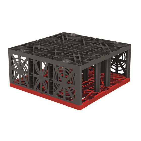
    3. DONNÉES TECHNIQUES DONNÉES TECHNIQUES Données techniques EcoBloc Inspect 230 GRAF Volume (brut/net) 230 l / 215 l Dimensions (longueur x largeur x hauteur) 800 x 800 x 360 mm Raccordements 4 x DN 200/DN 160/DN 110 + 4 x DN 110...
  • Page 37: Transport & Stockage

    TRANSPORT & STOCKAGE 4.1 Transport et stockage Les éléments d’ouvrage d‘infiltration ou de rétention EcoBloc Inspect 230 GRAF seront emballés en fonction des projets, généralement conditionnés sur une euro palette (module et plaque de fond). Il faudra ensuite assembler les éléments sur le site.
  • Page 38: Choix De L'emplacement

    5. CHOIX DE L’EMPLACEMENT CHOIX DE L’EMPLACEMENT Emplacement Choisissez l’emplacement de l‘ouvrage d’infiltration de sorte à ce que de l’eau s’en écoulant ne puisse pas endommager ni bâtiment ni autre installation à proximité. Afin d’empêcher érosion, ravinement ou affouillement, les ouvrages d’infiltration doivent être implantés à une distance équivalente à une fois et demi leur profondeur d’enfouissement.
  • Page 39: Dimensions De La Fouille

    5. CHOIX DE L’EMPLACEMENT Dimensions de la fouille Le dimensionnement de l’ouvrage d’infiltration pourra être réalisé selon la fiche de calcul DWA A-138. Veuillez nous contacter pour un dimensionnement. Les dimensions de la fouille sont déterminées d’après le dimensionnement ci-dessus et comme suit : - Longueur de l’ouvrage (donnée par le dimensionnement) + 1 m d’espacement de travail (tout autour de l’ouvrage) - Largeur de l’ouvrage (donnée par le dimensionnement) + 1 m d’espacement de travail (tout...
  • Page 40: Classes De Charges

    ≤ 12 t, poids lourds ≤ 30 t, ≤ 40 t ou ≤ 60 t. Les recouvrements max et min des différentes classes de charge sont repris dans le tableau 1. Tout autre type d’implantation doit toujours être réalisé en concertation avec la société GRAF. N’utilisez que du remblai (matériau / terre d’origine et/ou gravier) ayant un poids volumique maximal de 20kN/m³.
  • Page 41: Pose D'un Ouvrage D'infiltration

    7. POSE D’UN OUVRAGE D’INFILTRATION POSE D’UN OUVRAGE D’INFILTRATION La taille de la fouille est déterminée par les dimensions de l’ouvrage d’infiltration ainsi que de l’espace de travail tout autour d’environ 1 m de largeur, voir à cet effet chap.5.3 Préparation de la fouille Le fond de fouille doit être parfaitement plan, horizontal et solide.
  • Page 42 Inspect 230. Le sens de pose des parois de fermeture coïncide avec le sens d’écriture du logo GRAF. Vous pourrez réaliser des raccordements en DN 110, DN 160 ou DN 200 pour l’alimentation, les évents et/ou le canal d’inspection.
  • Page 43: Pose Du Tuyau D'alimentation

    7. POSE D’UN OUVRAGE D’INFILTRATION Pose du tuyau d’alimentation Coupez le géotextile en croix à l’emplacement prévu pour l’alimentation. Introduisez d’env. 20 cm le tuyau d’alimentation dans l’ouvrage puis collez ou soudez les restes de la coupe en croix sur le tuyau.
  • Page 44: Pose D'un Ouvrage De Rétention

    Une remontée de nappe peut faire remonter et endommager l’ouvrage et son environnement. Pour toute installation en présence de nappe phréatique, veuillez contacter GRAF. Toutes indications et informations techniques concernant le projet (nature du remblai, étude hydrologique, géologique et pédologique) sont à transmettre à la société GRAF.
  • Page 45: Installation Sous

    9. INSTALLATION SOUS PASSAGE VÉHICULES JUSQU’À 60 T INSTALLATION SOUS PASSAGE VÉHICULES JUSQU’À 60 T Remarques :  Les structures alvéolaires sont installées et raccordées conformément au chapitre 6 et 7. Les évents doivent être installés dans les espaces verts. ...
  • Page 46: Passage D'engins De Chantier

    12 t min 0,5 Réparti sur : uniformément sur 2 rouleaux Dimensions : 5,9 x 2,3 m min 0,8 Camions ≤ 60 tonnes Pour des matériaux et engins différents que ceux mentionnés ci-dessus, veuillez consulter la société GRAF 44 / 60...
  • Page 47: Autres Cas D'utilisation

    11. AUTRES CAS D’UTILISATION 11. AUTRES CAS D’UTILISATION La documentation présente ne traite que de l‘utilisation des éléments EcoBloc Inspect 230 GRAF servant à la rétention, au stockage ou infiltration d’eau de pluie. Toute autre utilisation doit avoir reçu l’accord de la société...
  • Page 48   garantía. Para todos los artículos complementarios adquiridos DATOS TÉCNICOS   través de GRAF, se suministran   Datos técnicos de GRAF EcoBloc Inspect inspect 230   instrucciones montaje TRANSPORTE Y ALMACENAMIENTO   adjuntos a los embalajes de   Transporte y almacenamiento  ...
  • Page 49: Indicaciones Generales

    DIN 18300 "Trabajos de movimientos de tierras" y DIN 4124 "Fosas de obra y zanjas". GRAF ofrece un amplio surtido de accesorios que están adaptados entre sí y que pueden crear sistemas completos. El uso de accesorios no aprobados por GRAF da lugar a la pérdida de la garantía legal/comercial.
  • Page 50: Indicaciones Generales Sobre Productos

    Elementos de canales GRAF EcoBloc Inspect inspect 230 402001 Placas finales GRAF EcoBloc Inspect inspect 402002 Elementos de conexión GRAF EcoBloc Inspect inspect, p. ej. 420015 juego de 10 ud. GRAF EcoBloc Inspect inspect flex 402005 Placa de fondo GRAF EcoBloc Inspect inspect flex...
  • Page 51: Datos Técnicos

    3. Datos técnicos Datos técnicos Datos técnicos de GRAF EcoBloc Inspect inspect 230 Volumen (bruto/neto) 230 litros /215 litros Medidas (larg.xanch.xalt.) 800 x 800 x 360 mm 4 x DN 200/DN 150/DN 100 + 4 x DN 100 Conexiones Peso...
  • Page 52: Transporte Y Almacenamiento

    Transporte y almacenamiento Transporte y almacenamiento Los elementos de canal EcoBloc Inspect inspect 230 de GRAF se embalan específicamente por proyecto. Normalmente, las piezas individuales de los elementos de canal (módulo y placa de fondo) se encuentran sobre una europaleta. A continuación, las piezas individuales deben montarse localmente.
  • Page 53: Selección De La Ubicación

    5. Selección de la ubicación Selección de la ubicación Ubicación La ubicación de la planta de filtración debe elegirse de modo que el agua expulsada no provoque daños a construcciones ni a otras instalaciones. Para evitar una socavación y un estancamiento, las plantas de filtración deben colocarse siempre a una distancia mínima de 1,5 veces la profundidad de la fosa de la obra.
  • Page 54: Selección De La Ubicación

    5. Selección de la ubicación Selección de la ubicación El dimensionamiento del canal se realiza conforme a la hoja de trabajo A-138 de la DWA. Si desea un dimensionamiento gratuito, póngase en contacto con nosotros. Las dimensiones de la base de la fosa de obra dependen del dimensionamiento arriba señalado, según lo indicado a continuación: Longitud del canal (dimensionamiento) + 1 m espacio de trabajo (continuo) Anchura del canal (dimensionamiento) + 1 m espacio de trabajo (continuo)
  • Page 55: Clases De Carga

    40 y camión60. En Tabla 1 se muestran las coberturas de tierra mín. y máx. de las diferentes clases de carga. En caso de situaciones de montaje diferentes deberá consultarse con GRAF. Se requieren materiales de relleno (material excavado reutilizable y/o grava) con un peso específico máximo de 20kN/m³.
  • Page 56: Montaje

    7. Montaje Montaje Las dimensiones de la fosa de obra dependen de las dimensiones de la planta de filtración así como de un espacio de trabajo continuo de una anchura aproximada de un metro, véase el capítulo 5.3. Preparación de la fosa de obra La base de la fosa de obra debe prepararse básicamente como plano horizontal, liso y estable.
  • Page 57 EcoBloc Inspect inspect 230. Las placas laterals deben posicionarse para que el logo GRAF se puede leer correctamente. Las entradas pueden realizarse en las conexiones de la placa final Eco en DN 100, DN 150 o DN 200.
  • Page 58: Montaje De La Entrada

    7. Montaje Montaje de la entrada En la superficie de entrada, el Geotextil se prepara con un corte X. El tubo de admisión se introduce unos 20 cm y el resto del corte X se pega o se suelda al tubo. Las ventilaciones necesarias se colocan de forma análoga.
  • Page 59: Estructura Como Volumen De Retención

    En estos casos se recomienda la instalación de un drenaje en el área de instalación. Para más detalles por favor póngase en contacto con Graf y con gusto le asesoraremos.
  • Page 60: Instalación Bajo Áreas De Tránsito Pesado Hasta Slw60

    9. Instalación bajo áreas de tránsito pesado hasta SLW60 Instalación bajo áreas de tránsito pesado hasta SLW60 Notas:  Los bloques Inspect Flex se instalan y conectan según apartado 6 y 7. Las ventilaciones deberán instalarse en zonas peatonales.  Los materiales de compactación de las diferentes capas de suelo pueden ...
  • Page 61: Circulación Con Máquinas De Construcción

    Apisonadoras, excavadoras Peso total: aprox. 12t mín. 0,5 distribuido sobre: Uniforme, sobre 2 rodillos Dimensión: 5,9 x 2,3 mín. 0,8 Vehículos camión60 En caso de desviación respecto a los materiales y equipos aquí indicados, consulte con GRAF. 59 / 60...
  • Page 62: Otros Casos De Aplicación

    La presente documentación trata exclusivamente del uso de los cuerpos de canales GRAF EcoBloc Inspect flex inspect 230 para la retención, la acumulación o la filtración de agua de precipitación. Todo uso distinto de los cuerpos de canales debe acordarse con Otto GRAF GmbH desde una perspectiva técnica, de los materiales y/o estática.
  • Page 63 Notizen / Notes / Notas...

Table des Matières