THOMSON TTV 1707 Manuel D'utilisation
Table des Matières
Les langues disponibles
Les langues disponibles
Liens rapides
CAMÉRA TTV 1707 / CCU DT 500
TTV 1707 CAMERA / DT 500 CCU
MANUEL D'UTILISATION
USER MANUAL
B1707M00LD
Ce document et toute mise à jour et/ou complèment d'information, ainsi que leurs copies, ne peu-
vent en aucun cas être reproduits, ni communiqués à une tierce partie, sans autorisation écrite de
THOMSON broadcast systems.
This document and any updates and/or supplemental information, including any copies thereof, can
not be reproduced, neither communicated to a third party, without written authorisation from
THOMSON broadcast systems.
Head Office
17, rue du Petit Albi
BP 8244
95801 Cergy Pontoise Cedex
FRANCE
CAM. OK
CAM.LOCK
EXT.REF.
COARSE
H
FINE
SC
SC/H
FRONT
PORCH
GENLOCK/
SOUND/
TRIAX
VIDEO
AUX
tel +33 1 34 20 70 00
fax +33 1 34 20 70 47
ON AIR
I
CAMERA
MAINS
RCP
ON
O
OFF
CABLE
OPEN
CCU
POWER
http://www.thomsonbroadcast.com
© 2000
THOMSON
broadcast systems
All rights reserved.
Chapitres
Table des Matières

Manuels Connexes pour THOMSON TTV 1707


Sommaire des Matières pour THOMSON TTV 1707
- Page 1 +33 1 34 20 70 00 95801 Cergy Pontoise Cedex fax +33 1 34 20 70 47 FRANCE http://www.thomsonbroadcast.com CAMÉRA TTV 1707 / CCU DT 500 TTV 1707 CAMERA / DT 500 CCU ON AIR CAMERA MAINS CAM. OK CAM.LOCK...
-
Page 2: Page Blanche
PAGE BLANCHE BLANK PAGE... - Page 3 CONSIGNES DE SECURITE .............. 9 CHAPITRE 1 SPÉCIFICATIONS ................15 CHAPITRE 2 INSTALLATION ................29 CHAPITRE 3 CAMÉRA - CONVERTISSEUR DC/DC ..........53 CHAPITRE 4 CONTRÔLE DE VOIE ............... 77 CHAPITRE 5 VISEURS 4 CM ET 14 CM ..............87 B1707M00LD THOMSON...
-
Page 5: Table Des Matières
2.1.1 - Montage du contrôle de voie avec un accessoire 1/2 19" ... 31 2.1.2 - Montage de deux contrôles de voie en baie ......34 2.2 - Alimentation secteur............. 36 2.3 - Audio ................37 B1707M00LD THOMSON TTV1707 / CCU DT500 Septembre 2000 Manuel utilisateur... - Page 6 3.1.2 - Côté droit ................. 56 3.1.3 - Côté gauche................58 3.1.4 - Face arrière................60 3.2 - Convertisseur DC/DC externe ........68 3.3 - Exploitation de la caméra ..........70 THOMSON TTV1707 / CCU DT500 B1707M00LD Manuel utilisateur Septembre 2000...
- Page 7 5.2.1 - Principales caractéristiques........... 94 5.2.2 - Accessoires ................95 5.2.3 - Description générale ............... 96 5.2.4 - Description des commandes..........97 5.2.5 - Montage du viseur sur son support ........98 B1707M00LD THOMSON TTV1707 / CCU DT500 Septembre 2000 Manuel utilisateur...
- Page 8 SECTION 1 - Version Française THOMSON TTV1707 / CCU DT500 B1707M00LD Manuel utilisateur Septembre 2000...
-
Page 9: Consignes De Securite
CONSIGNES DE SECURITE CONSIGNES DE SECURITE B1707M00LD THOMSON TTV1707 / CCU DT500 Septembre 2000 Manuel utilisateur... - Page 10 CONSIGNES DE SECURITE THOMSON TTV1707 / CCU DT500 B1707M00LD Manuel utilisateur Septembre 2000...
-
Page 11: Précautions Corporelles
CCU est reliée à un appareil de classe 2 (sans prise de terre) sous tension. Cordon d’Alimentation Utilisez le cordon d’alimentation fourni avec l’équipement. Surcharges électriques Respectez la plage de tension spécifiée. Mise à la Terre B1707M00LD THOMSON TTV1707 / CCU DT500 Septembre 2000 Manuel utilisateur... -
Page 12: Précautions Matérielles
Ventilation Pour éviter tout risque de surchauffe, ventilez correctement le produit. THOMSON TTV1707 / CCU DT500 B1707M00LD Manuel utilisateur Septembre 2000... - Page 13 Ne jamais utiliser de solvants puissants tels qu'alcool ou benzine. Remplacement de composant N’utilisez que des composants d’origine (ou agréé) THOMSON BROADCAST SYSTEMS. Remplacement de Pile La caméra contient une mémoire sauvegardée par une pile au lithium. Ce composant a une durée de vie suffisante pour ne jamais être changé.
- Page 14 CONSIGNES DE SECURITE THOMSON TTV1707 / CCU DT500 B1707M00LD Manuel utilisateur Septembre 2000...
-
Page 15: Spécifications
1.4.1.1 - Branchement du pupitre sur le contrôle de voie ......27 1.4.1.2 - Alimentation du pupitre ..............27 1.4.1.3 - Liaison SMPTE ................27 1.4.1.4 - Distance contrôle de voie pupitre............. 27 1.5 - Principes généraux de maintenance ......28 B1707M00LD THOMSON TTV1707 / CCU DT500 Septembre 2000 Manuel utilisateur... - Page 16 Chapitre 1 - Spécifications THOMSON TTV1707 / CCU DT500 B1707M00LD Manuel utilisateur Septembre 2000...
-
Page 17: Chapitre 1 - Spécifications Principales Caractéristiques
En fonctionnement : 0°C à +45°C - humidité relative 95 % sans condensation En stockage : -20°C à +55°C - humidité relative 95 % sans condensation Compatibilité électromagnétique et sécurités : Conforme aux directives CE (marquage CE) B1707M00LD THOMSON TTV1707 / CCU DT500 Septembre 2000 Manuel utilisateur... -
Page 18: Caméra
: > 55 % (Contour OFF) et 100 % après correction (Contour ON). Superpositions (fonction de l'objectif utilisé) : Zone 1 : 20 ns - Zone 2 : 30 ns - Zone 3 : 40 ns Signaux d'entrée : 1 Entrée microphone THOMSON TTV1707 / CCU DT500 B1707M00LD Manuel utilisateur Septembre 2000... - Page 19 En fonctionnement : -20°C à +45°C - humidité relative 95 % sans condensation. En stockage : -20°C à +55°C - humidité relative 95 % sans condensation. Compatibilité électromagnétique et sécurités : Conforme aux directives CE (marquage CE) B1707M00LD THOMSON TTV1707 / CCU DT500 Septembre 2000 Manuel utilisateur...
-
Page 20: Convertisseurs Dc/Dc
En fonctionnement: -20°C à +45°C - humidité relative 95 % sans condensation. En stockage: -20°C à +55°C - humidité relative 95 % sans condensation. Compatibilité électromagnétique et sécurités Conforme aux directives CE (marquage CE) THOMSON TTV1707 / CCU DT500 B1707M00LD Manuel utilisateur Septembre 2000... -
Page 21: Longueur Du Câble Triaxial Caméra / Contrôle De Voie
• La puissance maximum (50 W) délivrée par le convertisseur externe connecté sur l'embase "DC OUT" de la caméra est assurée pour une longueur maximum de câble triaxial spécifié dans le tableau ci dessus. B1707M00LD THOMSON TTV1707 / CCU DT500 Septembre 2000 Manuel utilisateur... -
Page 22: Présentation
élaborée à partir des trois voies R, V, B. Détail Correction Correction d’ouverture physiologique Centrage 100 % Sans correction " Signal vidéo avec corrections de contour et filtre optique passe bas THOMSON TTV1707 / CCU DT500 B1707M00LD Manuel utilisateur Septembre 2000... -
Page 23: Chapitre 1 - Spécifications Présentation
2 Vidéos retours dont une optionnelle, 1 liaison Interphonie, 1 Son "Micro d'ambiance", les signaux d'asservissement du générateur de base de temps de la caméra, les informations aller et retour de télécommande et l'énergie pour l'alimentation de la caméra. B1707M00LD THOMSON TTV1707 / CCU DT500 Septembre 2000 Manuel utilisateur... -
Page 24: Facilités D'exploitation
(fonctionnement en configuration "MICROCAM"). Un réglage continu de sensibilité du micro est également accessible sur l'arrière de la caméra. THOMSON TTV1707 / CCU DT500 B1707M00LD Manuel utilisateur Septembre 2000... - Page 25 Se référer au paragraphe 1.1.4 - Longueur du câble triaxial caméra / contrôle de voie. CAMÉRAS ASSOCIÉES La caméra 1707 s'intègre parfaitement à un environnement de caméras de types TTV1657, TTV1657D ou 1557D grâce à un système de commande identique. B1707M00LD THOMSON TTV1707 / CCU DT500 Septembre 2000 Manuel utilisateur...
-
Page 26: Configuration
GENLOCK/ SOUND/ • Interphonie TRIAX VIDEO POWER • Signalisations (ON AIR1, 2) • Micro ambiance • Secteur 230 V 50 Hz ou 110 V 60 Hz CONTRÔLE DE VOIE DT500 THOMSON TTV1707 / CCU DT500 B1707M00LD Manuel utilisateur Septembre 2000... -
Page 27: Chapitre 1 - Spécifications Principes Généraux D'exploitation
Le système d'exploitation utilise le protocole de transmission SMPTE. 1.4.1.4 - Distance contrôle de voie pupitre La distance maximum est de 100 mètres sous certaines conditions. Se référer au para- graphe 2.8 - Pupitre d’exploitation. B1707M00LD THOMSON TTV1707 / CCU DT500 Septembre 2000 Manuel utilisateur... -
Page 28: Chapitre 1 - Spécifications Principes Généraux De Maintenance
La maintenance de la caméra peut être effectuée avec ou sans contrôle de voie au moyen d'une carte outil (carte "TOOLS" disponible en option) permettant différentes configura- tions de la caméra. Se référer au manuel de maintenance de l'équipement TTV1707 DT500. THOMSON TTV1707 / CCU DT500 B1707M00LD Manuel utilisateur Septembre 2000... -
Page 29: Installation
2.6.2 - Equipement sans référence externe (mode libre)........ 48 2.7 - Adaptation aux commandes externes de signalisations d’antenne 2.8 - Pupitre d’exploitation ..............50 2.9 - Montage de l'attache câble sur la caméra ........52 B1707M00LD THOMSON TTV1707 / CCU DT500 Septembre 2000 Manuel utilisateur... - Page 30 Chapitre 2 - Installation THOMSON TTV1707 / CCU DT500 B1707M00LD Manuel utilisateur Septembre 2000...
-
Page 31: Montage Du Contrôle De Voie En Baie
1. Retirer l'oreille gauche du CCU DT500 en dévissant les deux vis de fixation. 2. Accoller le coffret support accessoire sur le flanc gauche du CCU DT500, les décrochements positionnés à l'arrière du CCU DT500. Coffret support accessoire B1707M00LD THOMSON TTV1707 / CCU DT500 Septembre 2000 Manuel utilisateur... - Page 32 Cache avant 5. Visser les deux vis de Ø 3 avec le tournevis à partir de l'intérieur du coffret support accessoire pour fixer le cache avant. 2 vis F/90 M3x4 THOMSON TTV1707 / CCU DT500 B1707M00LD Manuel utilisateur Septembre 2000...
-
Page 33: Montage De L'accessoire À Droite Du Contrôle De Voie
6. Visser les deux vis de Ø 3 avec le tournevis à partir de l'intérieur du CCU DT500 pour fixer le cache avant. 7. Fixer l'oreille droite du CCU DT500 (démontée en 1) à droite du coffret support accessoire. B1707M00LD THOMSON TTV1707 / CCU DT500 Septembre 2000 Manuel utilisateur... -
Page 34: Montage De Deux Contrôles De Voie En Baie
3. Retirer le bloc alimentation du CCU DT500 placé à gauche en dévissant ses 3 vis de fixation. 4. Placer le cache avant contre le flanc gauche du CCU DT500 placé à droite (une seule position convient). THOMSON TTV1707 / CCU DT500 B1707M00LD Manuel utilisateur Septembre 2000... - Page 35 6 vis F/90HC M4x5 Clé six pans 8. Placer l'ensemble des 2 CCU DT500 dans la baie 19" à l'emplacement désiré et le fixer grâce aux deux oreilles. B1707M00LD THOMSON TTV1707 / CCU DT500 Septembre 2000 Manuel utilisateur...
-
Page 36: Alimentation Secteur
Type de fusible : En 110 V ou 220 V : Valeur T 6,3 AH 250 V Référence:T9000671. 2 fusibles : • fusible de protection de l’équipement, • fusible de rechange. THOMSON TTV1707 / CCU DT500 B1707M00LD Manuel utilisateur Septembre 2000... -
Page 37: Chapitre 2 - Installation Audio
MIC IN -40dB Mise en/hors service de -60dB l’alimentation fantôme 48 V d’alimentaion MONITOR RET. 1 PROMPTER / RET. 2 microphone Entrée du microphone d’ambiance FACE ARRIÈRE DE LA CAMÉRA B1707M00LD THOMSON TTV1707 / CCU DT500 Septembre 2000 Manuel utilisateur... -
Page 38: Interphonie
• Le niveau d'entrée du Son "INTERPHONIE" est réglable sur la carte "SOUND/AUX" du Contrôle de Voie entre -6 dB et +18 dB. Le réglage s'effectue au moyen du commutateur S581 "0dB +12dB" et du potentiomètre R580 "LEVEL". THOMSON TTV1707 / CCU DT500 B1707M00LD Manuel utilisateur... - Page 39 Lorsque la liaison RTS/CLEARCOM est utilisée, la liaison interphonie 4 fils est indisponible. Le canal RTS/CLEARCOM doit avoir une terminaison de 200 Ω. S581 R540 R580 S540 S580 S560 SOUND / AUX PCB B1707M00LD THOMSON TTV1707 / CCU DT500 Septembre 2000 Manuel utilisateur...
-
Page 40: Vidéo
(digitales et composites) de l'équipement, la chrominance est coupée. En exploitation, S170 (Logiciel ≤ 47017011/C) et S171 doivent être en position "NORMAL". Z160 S170 S171 NTSC PAL BGH 6251 GENLOCK / VIDEO PCB THOMSON TTV1707 / CCU DT500 B1707M00LD Manuel utilisateur Septembre 2000... -
Page 41: Mise En Phase De L'équipement Avec Une Installation De Type Numérique
Les différents réglages et commutations s'effectuent sur et en face avant de la carte "GENLOCK/VIDEO". CAM.LOCK Z160 EXT.REF. COARSE S170 S171 NTSC FINE PAL BGH 6251 SC/H FRONT Commutations carte "GENLOCK/VIDEO" PORCH GENLOCK/ VIDEO Réglages carte "GENLOCK/VIDEO" B1707M00LD THOMSON TTV1707 / CCU DT500 Septembre 2000 Manuel utilisateur... -
Page 42: Equipement Asservi Sur Une Référence Externe Connectée Sur L'entrée "Gen Lock
• S170 commute un signal test de type mire de barres sur toutes les sorties vidéo du CCU. • "ΦH COARSE" régle la phase horizontale du signal numérique par pas de 592 ns. THOMSON TTV1707 / CCU DT500 B1707M00LD Manuel utilisateur... -
Page 43: Equipement Sans Référence Externe (Mode Libre)
"ΦSC/H" et "FRONT PORCH" en face avant de la carte. La sous porteuse du signal composite de sortie est asservie par rapport aux signaux de synchronisation. B1707M00LD THOMSON TTV1707 / CCU DT500 Septembre 2000 Manuel utilisateur... -
Page 44: Mise En Phase De L'équipement Avec Une Installation De Type Analogique
Les différents réglages et commutations s'effectuent sur et en face avant de la carte "GENLOCK/VIDEO". CAM.LOCK Z160 EXT.REF. COARSE S170 S171 NTSC FINE PAL BGH 6251 SC/H FRONT Commutations carte "GENLOCK/VIDEO" PORCH GENLOCK/ VIDEO Réglages carte "GENLOCK/VIDEO" THOMSON TTV1707 / CCU DT500 B1707M00LD Manuel utilisateur Septembre 2000... -
Page 45: Equipement Asservi Sur Une Référence Externe Connectée Sur L'entrée "Gen Lock
-4,5 µs à +5 µs Phasage sous porteuse La phase sous porteuse du signal composite de sortie par rapport au signal de référence externe (BBS) s'ajuste avec la roue codeuse "ΦSC". B1707M00LD THOMSON TTV1707 / CCU DT500 Septembre 2000 Manuel utilisateur... -
Page 46: Référence Externe Sans Black Burst
• "ΦH FINE" : Réglage par pas de 37 ns. La plage de variation du signal composite de sortie par rapport au signal de référence est d'environ 9,5 µs (-4,5 µs +5 µs). THOMSON TTV1707 / CCU DT500 B1707M00LD Manuel utilisateur... - Page 47 Nota : Ce réglage n'agit pas sur la largeur de la suppression horizontale. PAL 1,5 ±0,3 µs (1,65 µs ±0,1 µs PAL I) NTSC 1,5 ±0,1 µs Front porch sorties composites 1 et 2 B1707M00LD THOMSON TTV1707 / CCU DT500 Septembre 2000 Manuel utilisateur...
-
Page 48: Equipement Sans Référence Externe (Mode Libre)
Le réglage de la durée du palier de garde avant du signal composite de sorties'effectue avec la roue codeuse "FRONT PORCH". Nota : Ce réglage n'agit pas sur la largeur de la suppression horizontale. THOMSON TTV1707 / CCU DT500 B1707M00LD Manuel utilisateur... -
Page 49: Adaptation Aux Commandes Externes De Signalisations D'antenne
S900-S901 +5 V à +48 V Voltage Boucle Contact Nota : Les commutateurs S1000 et S1001 ne sont pas utilisés. S800 S801 S900 S901 S1000 S1001 SOUND / AUX PCB B1707M00LD THOMSON TTV1707 / CCU DT500 Septembre 2000 Manuel utilisateur... -
Page 50: Pupitre D'exploitation
La liaison est normalement assurée par un câble blindé 5 paires de référence : • BC041.001 - longueur 1 mètre, ou • BC041.015 - longueur 15 mètres, ou • BC041.050 - longueur 50 mètres, ou • BC042100AA - longueur 100 mètres THOMSON TTV1707 / CCU DT500 B1707M00LD Manuel utilisateur Septembre 2000... - Page 51 OCP POWER SUPPLY (+ ON AIR 1, ON AIR 2) (+ ON AIR 1, ON AIR 2) Tresse de masse du câble SCHÉMA DU CÂBLE 100 MÈTRES DE LIAISON CCU OCP B1707M00LD THOMSON TTV1707 / CCU DT500 Septembre 2000 Manuel utilisateur...
-
Page 52: Montage De L'attache Câble Sur La Caméra
2.9 - MONTAGE DE L'ATTACHE CÂBLE SUR LA CAMÉRA L'attache câble livré avec la caméra se monte sur la vis de fixation de la courroie de portage. " Vers le contrôle de voie THOMSON TTV1707 / CCU DT500 B1707M00LD Manuel utilisateur Septembre 2000... -
Page 53: Caméra - Convertisseur Dc/Dc
3.3.1 - Commandes cadreur ................70 3.3.2 - Fonctions d'exploitation cadreur ............71 3.3.2.1 - Arborescence des fonctions............. 71 3.3.2.2 - Description des fonctions..............71 3.3.2.3 - Fonctions marqueurs ............... 73 B1707M00LD THOMSON TTV1707 / CCU DT500 Septembre 2000 Manuel utilisateur... - Page 54 Chapitre 3 - Caméra - Convertisseur DC/DC THOMSON TTV1707 / CCU DT500 B1707M00LD Manuel utilisateur Septembre 2000...
-
Page 55: Description De La Caméra
3.1 - DESCRIPTION DE LA CAMÉRA 3.1.1 - Dimensions, poids Les dimensions sont exprimées en mm. Largeur : 127 mm Poids : Environ 5,5 kg avec viseur 4 cm sans objectif B1707M00LD THOMSON TTV1707 / CCU DT500 Septembre 2000 Manuel utilisateur... -
Page 56: Côté Droit
5. Orifices d'évacuation d'air chaud. Un ventilateur est fixé derrière ces orifi- ces. Ne pas les obturés. Le ventilateur est en service pour une tempé- rature ambiante supérieure à environ 35°C. THOMSON TTV1707 / CCU DT500 B1707M00LD Manuel utilisateur Septembre 2000... - Page 57 Pour la sélection des vidéo, se référer à la partie EXPLOITATION de ce chapitre. 9. Bague de serrage de la colonne support Désserrer cette bague pour permettre le viseur réglage longitudinal du viseur. B1707M00LD THOMSON TTV1707 / CCU DT500 Septembre 2000 Manuel utilisateur...
-
Page 58: Côté Gauche
14.Epaulière coulissante. Pour régler l'épaulière : • Appuyer sur le poussoir (13). • Faire glisser l'épaulière. • Relâcher le poussoir. 3.1.3 - Côté gauche 1. Fixation de la courroie de portage. THOMSON TTV1707 / CCU DT500 B1707M00LD Manuel utilisateur Septembre 2000... - Page 59 4. Identification de la caméra. La caméra est identifié à l'installation au moyen des chiffres livrés avec l'équipement. La fixation sur la caméra est effectuée au moyen d'un support aimanté. B1707M00LD THOMSON TTV1707 / CCU DT500 Septembre 2000 Manuel utilisateur...
-
Page 60: Face Arrière
(OFF) service de la caméra. caméra est alimentée. 2 Bouton "CALL". Appel pour attirer l'attention de l'opérateur du pupitre. L'appui sur ce bouton allume l'inscription "CALL" du pupitre d'exploitation. CALL THOMSON TTV1707 / CCU DT500 B1707M00LD Manuel utilisateur Septembre 2000... - Page 61 La sélection "RET1" ou "RET2" est déterminée position commutateur "VIDEO RET". Pour connaître le détail des fonctions d'exploitation se référer au paragraphe 3.3.2 - Fonctions d'exploitation cadreur, de ce cha- pitre. B1707M00LD THOMSON TTV1707 / CCU DT500 Septembre 2000 Manuel utilisateur...
-
Page 62: Cadre "Triax
(même non chargé) sur la caméra en fonc- tionnement, le système de sécurité fera dis- joncter la caméra. Le raccordement du convertisseur doit se faire la caméra étant hors tension. THOMSON TTV1707 / CCU DT500 B1707M00LD Manuel utilisateur Septembre 2000... -
Page 63: Cadre "Mic/Intercom
SPLIT HEAD HEAD" est une option permettant de séparer l'ensemble bloc d'analyse du corps de la caméra afin de disposer d'un ensemble (objectif + bloc d'ana- lyse) de dimensions réduites (MICROCAM). B1707M00LD THOMSON TTV1707 / CCU DT500 Septembre 2000 Manuel utilisateur... - Page 64 "48 V/OFF" en fonction du type de MIC IN micro utilisé. Embase Type : XLR NC3FD-V Réf : 91555161 1 : GND 3 : MIC Y 2 : MIC X THOMSON TTV1707 / CCU DT500 B1707M00LD Manuel utilisateur Septembre 2000...
- Page 65 Le microphone doit avoir une sensi- bilité de -40 dB et être de type électrostati- que. Exemples de microcasques utilisés : • AVS 40811H (2 écouteurs) • AVS 40891H (1 écouteur) B1707M00LD THOMSON TTV1707 / CCU DT500 Septembre 2000 Manuel utilisateur...
- Page 66 Embase "JACK" sont pas connectés. Embase Type: JACK S2-BBB/BLK Réf: 91616196 Prise correspondante Type: JACK FLJCN " Réf: T1004861 1 :EARPHONE- (GND) 2 :EARPHONE+ MIC - (GND) 3 :MIC + THOMSON TTV1707 / CCU DT500 B1707M00LD Manuel utilisateur Septembre 2000...
-
Page 67: Cadre "Video Out
(Niveau : 1 Vcc typique / 75 Ohms). Type: LX-6P-DLT1-P1 La présence de la vidéo "PROMPTER/ Réf: T1001245 RET2" dépend de la longueur du câble triaxial. Se référer au chapitre "SPECIFI- CATION". B1707M00LD THOMSON TTV1707 / CCU DT500 Septembre 2000 Manuel utilisateur... -
Page 68: Convertisseur Dc/Dc Externe
TIONS" de ce manuel. Vis de fixation sur la semelle de la caméra Les dimensions sont exprimées en mm. DC OUT 13V / 50W DC OUT 24 V / 50 W DC IN THOMSON TTV1707 / CCU DT500 B1707M00LD Manuel utilisateur Septembre 2000... -
Page 69: Chapitre 3 - Caméra - Convertisseur Dc/Dc Convertisseur Dc/Dc Externe
Le raccordement du convertisseur doit se faire la caméra étant hors tension. Voyant allumé : La tension DC OUT est présente en sortie du convertisseur. B1707M00LD THOMSON TTV1707 / CCU DT500 Septembre 2000 Manuel utilisateur... -
Page 70: Exploitation De La Caméra
PROMPTER / RET. 2 avec la commande "VTR" de l'objectif. • "(ON)" le microphone est en service. Les positions "ON" et "REM" sont stables. La po- sition "(ON)" est instable. THOMSON TTV1707 / CCU DT500 B1707M00LD Manuel utilisateur Septembre 2000... -
Page 71: Fonctions D'exploitation Cadreur
• PSH: La vidéo "RET1" ou "RET2" est affichée dans le viseur pendant l'appui de la touche "RET". • MEM: Un premier appui sur la touche "RET" affiche la vidéo "RET1" ou "RET2" et un B1707M00LD THOMSON TTV1707 / CCU DT500 Septembre 2000 Manuel utilisateur... - Page 72 3.3.2.3 - Fonctions marqueurs). • VF SELECT: Sélection du signal vidéo viseur: • Y: Signal de luminance • ENC: Vidéo codée • COL: Y, CR, CB (utilisés avec un viseur couleur). THOMSON TTV1707 / CCU DT500 B1707M00LD Manuel utilisateur Septembre 2000...
-
Page 73: Fonctions Marqueurs
• 90%: La zone de sauvegarde représente 90% de l'image. • 100%: La zone de sauvegarde représente 100% de l'image. 16/9 Safety zone: 90 (or 100%) Safety zone: 90 (or 100%) B1707M00LD THOMSON TTV1707 / CCU DT500 Septembre 2000 Manuel utilisateur... - Page 74 WIDTH BOX: Réglage de la largeur du cadre ajustable. HEIGHT BOX: Réglage de la hauteur du cadre ajustable. WIDTH HEIGHT V. POS. H. POS. PRGM MARKER 2:(Fonctions identiques au PRGM MARKER1). THOMSON TTV1707 / CCU DT500 B1707M00LD Manuel utilisateur Septembre 2000...
- Page 75 Permet de choisir les différents types de marqueurs (MARK2) dont la mise en service est commandée soit par: • La fonction "SELECT MARKER : 2" du menu cadreur. • Les commutateurs "ZEBRA-MARKS" des viseurs 4 cm ou 14 cm. B1707M00LD THOMSON TTV1707 / CCU DT500 Septembre 2000 Manuel utilisateur...
- Page 76 Chapitre 3 - Caméra - Convertisseur DC/DC Exploitation de la caméra THOMSON TTV1707 / CCU DT500 B1707M00LD Manuel utilisateur Septembre 2000...
-
Page 77: Contrôle De Voie
Chapitre 4 - Contrôle de voie Chapitre 4 Contrôle de voie 4.1 - Description ..................79 4.1.1 - Dimensions, poids ................79 4.1.2 - Face arrière ..................80 4.1.3 - Face avant ................... 84 B1707M00LD THOMSON TTV1707 / CCU DT500 Septembre 2000 Manuel utilisateur... - Page 78 Chapitre 4 - Contrôle de voie THOMSON TTV1707 / CCU DT500 B1707M00LD Manuel utilisateur Septembre 2000...
-
Page 79: Description
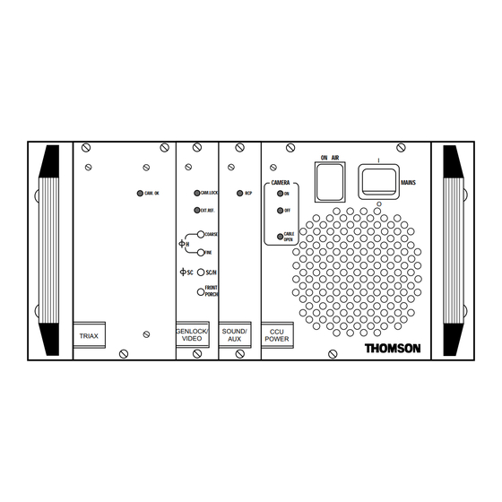
EXT.REF. CABLE COARSE OPEN FINE SC/H FRONT PORCH GENLOCK/ SOUND/ TRIAX VIDEO POWER Poids: Environ 7Kg Pour le montage du contrôle de voie en baie, se référer au chapitre "INSTALLATION". B1707M00LD THOMSON TTV1707 / CCU DT500 Septembre 2000 Manuel utilisateur... -
Page 80: Face Arrière
CHANGEMENT DU FUSIBLE Déconnecter la fiche secteur pour accéder au fusible. Le fusible est situé dans l’embase secteur qui contient également un fusible de rechange. THOMSON TTV1707 / CCU DT500 B1707M00LD Manuel utilisateur Septembre 2000... - Page 81 3 : GO B2 8 : GO A2 à destination du pupitre et de la caméra sont 4 : GND 9 : GND ajoutées à "PV RCP". 5 : PV RC B1707M00LD THOMSON TTV1707 / CCU DT500 Septembre 2000 Manuel utilisateur...
- Page 82 à la caméra. caméra. Tension de sortie: 52 VDC CAMERA Courant maximum: 3 A Embases: • LEMO 75 Ω • LEMO 50 Ω • FISCHER • KINGS • DAMAR HAGEN THOMSON TTV1707 / CCU DT500 B1707M00LD Manuel utilisateur Septembre 2000...
- Page 83 1Vcc/75 Ohms. Embases COMPOSITE Type: P2189-A V. B. S. Réf: T9003306 11.Embases "SERIAL DIGITAL OUTPUT". Sorties du signal numérique série 4:2:2 , 270Mbits. Embases+câble SERIAL DIGITAL OUTPUT Type: 98230x-021-009.0 Réf: T6000091 B1707M00LD THOMSON TTV1707 / CCU DT500 Septembre 2000 Manuel utilisateur...
-
Page 84: Face Avant
"GEN LOCK" du contrôle de voie. 4. Voyant «RCP» Ce voyant allumé indique la présence d’un pupitre sur l’embase «REMOTE» du con- trôle de voie. THOMSON TTV1707 / CCU DT500 B1707M00LD Manuel utilisateur Septembre 2000... - Page 85 à l’antenne («ON AIR1»). ON AIR 7. Interrupteur «MAINS» switch Interrupteur de mise en/hors fonctionne- ment de l’équipement • «I»: L’équipement en fonctionnement. • «O»: L’équipement est hors fonctionne- ment. MAINS B1707M00LD THOMSON TTV1707 / CCU DT500 Septembre 2000 Manuel utilisateur...
- Page 86 Chapitre 4 - Contrôle de voie Description THOMSON TTV1707 / CCU DT500 B1707M00LD Manuel utilisateur Septembre 2000...
- Page 87 5.2.1 - Principales caractéristiques ..............94 5.2.2 - Accessoires ..................95 5.2.3 - Description générale................96 5.2.4 - Description des commandes ............... 97 5.2.5 - Montage du viseur sur son support ............. 98 B1707M00LD THOMSON TTV1707 / CCU DT500 Septembre 2000 Manuel utilisateur...
-
Page 88: Viseurs 4 Cm Et 14 Cm
Chapitre 5 - Viseurs 4 cm et 14 cm THOMSON TTV1707 / CCU DT500 B1707M00LD Manuel utilisateur Septembre 2000... -
Page 89: Chapitre 5 - Viseurs 4 Cm Et 14 Cm Viseur 4 Cm
à l’intérieur, le capot ne doit être démonté que par du personnel qualifié. 5.1.2 - Commandes et fonctions 1. Bague de mise au point 2. Oeilleton B1707M00LD THOMSON TTV1707 / CCU DT500 Septembre 2000 Manuel utilisateur... - Page 90 Pour extraire le doublet tourner la bague dans le sens indiqué sur le dessin et tirer. 12.Voyant ON AIR 1 Ce voyant s'allume lorsque la caméra est à l'antenne (ON AIR 1). THOMSON TTV1707 / CCU DT500 B1707M00LD Manuel utilisateur...
-
Page 91: Signalisations Lumineuses
être à la limite de visibilité de la barre la plus sombre de la mire. 3. Régler le potentiomètre "CONT" pour voir toutes les barres de la mire, sans saturation de la barre la plus blanche. B1707M00LD THOMSON TTV1707 / CCU DT500 Septembre 2000 Manuel utilisateur... -
Page 92: Cablage De La Prise De Raccordement Du Viseur
(Not Used with 1707) 18 : Not connected 8 : Not connected 19 : Not connected 9 : MISO 1 OUT 20 : Not connected 10 : MOSI 1 IN THOMSON TTV1707 / CCU DT500 B1707M00LD Manuel utilisateur Septembre 2000... -
Page 93: Réglages Mécaniques
• Avec la caméra, viser un objet lointain. Ajuster la mise au point. • Tout en observant avec l’oeil gauche laissé libre le même objet, tourner la bague de mise au point pour que l’image dans le viseur soit nette. B1707M00LD THOMSON TTV1707 / CCU DT500 Septembre 2000 Manuel utilisateur... -
Page 94: Viseur 14 Cm
Pour éviter tout risque de destruction, ne pas exposer cet appareil à la pluie ou à l’humidité. A cause de la présence de hautes tensions à l’intérieur, le capot ne doit être démonté que par du personnel qualifié. THOMSON TTV1707 / CCU DT500 B1707M00LD Manuel utilisateur Septembre 2000... -
Page 95: Chapitre 5 - Viseurs 4 Cm Et 14 Cm Viseur 14 Cm
Câble de liaison avec la caméra Visière longue Fixation du viseur sur Fixation du viseur sur l’arrière de la caméra l’arrière de la caméra ou sur la poignée SUPPORTS ORIENTABLE B1707M00LD THOMSON TTV1707 / CCU DT500 Septembre 2000 Manuel utilisateur... -
Page 96: Description Générale
N.C. N.C. " & ON AIR1 " SS (Slave Select) N.C. MOSI ' ! " # MISO N.C. N.C. " POWER IN (11V/17V) N.C. POWER GND & THOMSON TTV1707 / CCU DT500 B1707M00LD Manuel utilisateur Septembre 2000... -
Page 97: Description Des Commandes
Mise en/hors service des voyants "ON AIR" situés sur la capot du viseur. 6. Potentiomètre "BRIGHT" Réglage de LUMIÈRE du viseur. 7. Voyant "ON AIR 2" Ce voyant s'allume lorsque la caméra est en préparation avant de passer à l'antenne. B1707M00LD THOMSON TTV1707 / CCU DT500 Septembre 2000 Manuel utilisateur... -
Page 98: Montage Du Viseur Sur Son Support
Chapitre 5 - Viseurs 4 cm et 14 cm Viseur 14 cm 5.2.5 - Montage du viseur sur son support THOMSON TTV1707 / CCU DT500 B1707M00LD Manuel utilisateur Septembre 2000...