Publicité
Les langues disponibles
Les langues disponibles
Liens rapides
ACTROS MP4 - EURO 6
Calidad en
Empresa
Automoción
Registrada
IATF 16949
ISO 9001
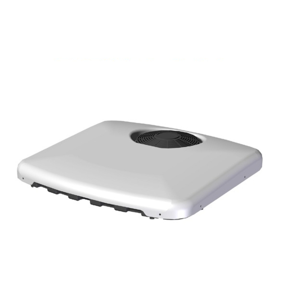
SLIM FIT
MERCEDES
Instrucciones de Montaje
Mounting Instructions
Instructions de Montage
Montageanweisungen
Istruzioni di Montaggio
®
ES
Spanish
EN
English
FR
French
GE
German
IT
Italian
220AA35384
Publicité

Manuels Connexes pour dirna Bergstrom bycool green line SLIM FIT MERCEDES ACTROS MP4


Sommaire des Matières pour dirna Bergstrom bycool green line SLIM FIT MERCEDES ACTROS MP4
- Page 1 ® SLIM FIT MERCEDES ACTROS MP4 - EURO 6 Instrucciones de Montaje Spanish Mounting Instructions English Instructions de Montage French Montageanweisungen German Istruzioni di Montaggio Italian Calidad en Empresa Automoción Registrada 220AA35384 IATF 16949 ISO 9001...
- Page 2 SLIM FIT ® Herramientas Recomendaciones Para el montaje Juego de Llaves Torx Juego de Llaves Allen • Antes de iniciar el montaje leer las instrucciones y Llave fija 13, 14, 22 seguirlas durante el proceso de instalacion. Tijeras Flexómetro • Usar herramientas adecuadas para...
- Page 3 SLIM FIT ® Desmontar escotilla y los elementos de fijación y entregar éstos al cliente.
- Page 4 SLIM FIT ® Pegue la junta EPDM 30x25 alrededor del hueco escotilla (mirar detalle para cortar los bordes finales de la unión de la junta). Junta EPDM Nervio Atención: La junta EPDM tiene que estar pegada junto al saliente del hueco de la escotilla. 15 mm COMO CORTAR LA JUNTA EPDM PARA EVITAR FILTRACIÓN DE AGUA EN LA...
- Page 5 SLIM FIT ® Posicionar el equipo sobre la junta introduciendo el panel interior de distribución en el hueco de escotilla. ¡Atención! Al colocar el equipo sobre el hueco escotilla, verificar que las salidas de desagüe no queden obstruidas por la junta EPDM. Escotilla Roscar (4) hexágonos M8/125x26 con arandela goma, arandela plana en insertos de la base y...
- Page 6 SLIM FIT ® Roscar (2) hexágonos M6 L=50 en la parte trasera del equipo (sentido marcha) con arandela de goma y arandela plana y apretar con un par de apriete de 4,75±10% Nm. Roscar (2) hexágonos M6 L=98 en la parte delantera del equipo (sentido de la marcha) con arandela de goma y arandela plana y apretar con un par de apriete de 4,75±10% Nm.
- Page 7 SLIM FIT ® Retirar consola y apretar tornillos M8/125x45 hasta hacer tope con los hexágonos para fijar el equipo.
- Page 8 SLIM FIT ® VISTA EXPLOSIONADA LATERAL HASTA LA FIJACIÓN DE LAS CONSOLAS Arandela goma Arandela goma Junta EPDM 30x25 Arandela Arandela plana Ø 6 plana Ø 6 Techo cabina (2) M6 M-H L=98 (2) M6 M-H L=50 Panel interior de distribución de aire Tapizado Arandela plana Ø...
- Page 9 SLIM FIT ® INSTRUCCIONES DETALLADAS SOBRE CONEXIÓN CABLEADO ALIMENTACIÓN Conectar el cable de alimentación al equipo, fijar al techo con soportes con adhesivo y bridas. Después bajar el cableado por la parte trasera de la cabina.
- Page 10 SLIM FIT ® Conectar el otro extremo del cableado y llevar el cable positivo (azul) a caja de conexiones en posición X4. Nota: Dependiendo de la ubicación de la caja de conexiones el cable positivo sobrará en longitud. Cortar éste a longitud deseada. Introducir cableado por gomino suministrado Pasar cableado por posición X4 y grapar terminal...
- Page 11 SLIM FIT ® Llevar el cable marrón (negativo) a caja especial para ello. Nota: Normalmente suele estar cerca de las baterías. Dependiendo de la ubicación de las baterías sobrará cableado marrón, cortar a medida deseada y grapar terminal suministrado. Colocar adhesivos seguridad cableado, en un lugar visible para recordar que hay que desconectarlo cada vez que se quiera abatir la cabina.
- Page 12 SLIM FIT ® Esquema eléctrico ¡AVISO IMPORTANTE! Precaución de no invertir las polaridades al conectar la alimentación en el equipo. Si esto sucediera el panel de control no se enciende y el equipo no funciona. Sensor aire de retorno Soplador centrífugo Control electrónico...
- Page 13 SLIM FIT ®...
- Page 14 ! Warnings The installing personnel must have a sufficient training in vehicles air conditioning. dirna Bergstrom, s. l. shall not be responsible for ! Warning breakdowns or damages coming from an inadequate handling or installation of the equipment or from...
- Page 15 SLIM FIT ® Take down the hatch and the fastening elements, and hand them over to the customer.
- Page 16 SLIM FIT ® Attach the EPDM 30x25 seal around the hatch gap (see the details to cut the ends of the seal joint). EPDM seal Nerve Take care: The EPDM seal must be secured to the projecting edge of the hatch gap. 15 mm HOW TO CUT EPDM GASKET TO AVOID WATER FILTRATION INTO THE CABIN...
- Page 17 SLIM FIT ® Position the unit on the seal, introducing the interior distribution panel in the hatch gap. Caution! When positioning the unit above the hatch gap, check that the wastewater run-offs are not blocked by the EPDM seal. Hatch Screw (4) M8/125x26 hexagons with rubber washer, flat washer in the base inserts, and tighten with a torque of 12.7±10 Nm.
- Page 18 SLIM FIT ® Screw (2) M6 L=50 hexagons on the rear of the unit (direction of travel) with rubber washer and flat washer, and tighten with a torque of 4.75±10% Nm. Screw (2) M6 L=98 hexagons on the rear of the unit (direction of travel) with rubber washer and flat washer, and tighten with a torque of 4.75±10% Nm.
- Page 19 SLIM FIT ® Remove the console and tighten M8/125x45 screws until it comes up against the hexagons in order to secure the unit.
- Page 20 SLIM FIT ® EXPLODED SIDE VIEW THROUGH TO CONSOLE ATTACHMENT Rubber washer Rubber washer 30x25 EPDM seal Ø6 Flat Ø6 Flat washer washer Cabin roof (2) M6 M-H L=98 Interior air distribution panel (2) M6 M-H L=50 Upholstery Ø8 Flat washer Grower washer Ø...
- Page 21 SLIM FIT ® DETAILED INSTRUCTIONS ON POWER CABLE CONNECTION Connect the power cable to the unit, secure to the roof with the mounts and adhesive and flanges. Then lower the wiring through the rear of the cabin.
- Page 22 SLIM FIT ® Connect the other end of the wire and connect the positive wire (blue) to the connections box in position X4. Note: Depending on the location of the connections box, the positive wire will have excess length. Cut this to the required length.
- Page 23 SLIM FIT ® Run the brown wire (negative) to the specially fitted box. Note: This is normally close to the batteries. Depending on the location of the batteries, the brown wire will have excess length; cut to the required size and clamp the supplied terminal. Position wire safety stickers in a visible place as a reminder to disconnect every time the cabin is tilted.
- Page 24 SLIM FIT ® Electric wiring IMPORTANT WARNING! Take care not to invert polarities when connecting the unit to the power supply. If this were to happen, the control panel would not come on and the unit would not work. Return air sensor Centrifugal blower...
- Page 25 SLIM FIT ®...
- Page 26 L’installateur devra posséder la formation pertinente en air conditionné sur véhicules. ! Attention dirna Bergstrom, s.l., ne sera pas responsable des dommages ou des bris dérivés d’une Lors de l’installation de l’appareil d’air conditionné sur le installation ou d’une manipulation incorrecte ni toit, il faudra protéger la partie supérieure de la cabine...
- Page 27 SLIM FIT ® Démonter l’écoutille et les éléments de fixation et les remettre au client.
- Page 28 SLIM FIT ® Coller le joint EPDM 30x25 autour du creux de l’écoutille (observer le détail pour couper les bords finaux de l’union du joint). Joint EPDM Nervure Attention: Le joint EPDM doit être collé près du bord de l’espace de la trappe. 15 mm COMMENT COUPER LE JOINT EPDM POUR ÉVITER LA FILTRATION D’EAU DANS LA...
- Page 29 SLIM FIT ® Positionner l’appareil sur le joint en introduisant le panneau intérieur de distribution dans l’espace de l’écoutille. Attention ! Avant de placer l’équipement sur le creux de l’écoutille, il faut vérifier que les sorties d’écoulement ne soient pas bouchées par le joint EPDM.
- Page 30 SLIM FIT ® Visser (2) hexagones M6 L=50 sur la partie arrière de l’appareil (sens de la marche) avec une rondelle en caoutchouc et une rondelle plane puis serrer avec un couple de serrage de 4,75±10% Nm. Visser (2) hexagones M6 L=98 sur la partie arrière de l’appareil (sens de la marche) avec une rondelle en caoutchouc et une rondelle plane puis serrer avec un couple de serrage de 4,75±10% Nm.
- Page 31 SLIM FIT ® Retirer la console et serrer les vis M8/125x45 jusqu’à atteindre la butée des hexagones pour fixer l’équipement.
- Page 32 SLIM FIT ® VUE ÉCLATÉE LATERALE JUSQU’A LA FIXATION DES CONSOLES Rondelle caoutchouc Rondelle caoutchouc Joint EPDM 30x25 Rondelle Rondelle plate Ø 6 plate Ø 6 Plafond cabine (2) M6 M-H L=98 (2) M6 M-H L=50 Panneau intérieur de distribution d’air Rondelle plate Ø...
- Page 33 SLIM FIT ® INSTRUCTIONS DÉTAILLÉES SUR LA CONNEXION DU CÂBLAGE D’ALIMENTATION Connecter le câble d’alimentation à l’équipement, fixer au plafond avec des supports à l’aide d’adhésifs et de brides. Ensuite, baisser l’équipement par la partie arrière de la cabine.
- Page 34 SLIM FIT ® Connecter l’autre extrémité du câblage et porter le câble positif (bleu) à la boîte de jonction sur la position X4. Remarque: en fonction de l’emplacement de la boîte de jonction, il est possible qu’il y ait de la longueur en trop.
- Page 35 SLIM FIT ® Porter le câble marron (négatif) à la boîte spéciale prévue à cet effet. Remarque: l’emplacement se trouve normalement près des batteries. En fonction de l’emplacement des batteries, il est possible qu’il y ait du câble marron en trop. Couper à la mesure désirée et agrafer le terminal fourni.
- Page 36 SLIM FIT ® Schéma électrique AVIS IMPORTANT ! Attention de ne pas inverser les polarités dans la connexion de l’alimentation à l’équipement. Si cela se produisait, la Panneau De Contrôle ne s’allumerait pas et l’équipement ne fonctionnerait pas. Sonde d’air de retour Souffleur centrifuge...
- Page 37 SLIM FIT ®...
- Page 38 Lage gebracht wurde, wieder ! Warnhinweise einzuschalten. Der Installateur muss im Bereich Fahrzeug-Klimaanlagen ausreichend geschult sein. dirna Bergstrom, s.l. übernimmt keine Verantwortung ! Achtung für Schäden oder Brüche aufgrund einer nicht ordnungsgemäßen Installation oder Bedienung des Geräts oder den Austausch von Teilen bzw.
- Page 39 SLIM FIT ® Luke und deren Befestigungselemente ausbauen und diese dem Kunden aushändigen.
- Page 40 SLIM FIT ® EPDM-Dichtung (30x25 Lukenaussparung herum kleben (siehe Detailzeichnung für das Zurechtschneiden der äußeren Fugenränder der Dichtung). EPDM-Dichtung Rippe Achtung: Die EPDM-Dichtung muss am Vorsprung der Lukenaussparung angeklebt sein. 15 mm WIE DIE EPDM-DICHTUNG GESCHNITTEN A WIRD, UM FILTRATIONEN IN DER KABINE ZU VERMEIDEN A- Dichtung aufkleben und dabei einen Papierschutz von 100 mm auf jeder Seite...
- Page 41 SLIM FIT ® Anlage auf die Dichtung legen und die innere Luftverteilertafel durch die Lukenöffnung stecken. Achtung! Beim Auflegen des Geräts auf die Lukenaussparung darauf achten, dass die Entwässerungsausgänge nicht von der EPDM- Dichtung zusammengedrückt werden. Luke (4) Sechskant-Verbindungsmuttern M8/125x26 mit Gummi-Unterlegscheibe und Flachscheibe in die Einsätze der Grundplatte einschrauben und mit einem Anzugsmoment von 12,7±10 Nm anziehen.
- Page 42 SLIM FIT ® (2) Sechskant-Verbindungsmuttern M6 L=50 am hinteren Teil des Geräts (Fahrtrichtung) mit Gummi- Unterlegscheibe und Flachscheibe einschrauben und mit einem Anzugsmoment von 4,75±10% Nm anziehen. (2) Sechskant-Verbindungsmuttern M6 L=98 am hinteren Teil des Geräts (Fahrtrichtung) mit Gummi- Unterlegscheibe und Flachscheibe einschrauben und mit einem Anzugsmoment von 4,75±10% Nm anziehen.
- Page 43 SLIM FIT ® Konsole entfernen und Schrauben M8/125x45 Anschlag Sechskant- Verbindungsmuttern anziehen, um das Gerät zu befestigen.
- Page 44 SLIM FIT ® SEITLICHE EXPLOSIONSANSICHT BIS ZUR BEFESTIGUNG DER KONSOLEN Gummiunterlegscheibe Gummiunterlegscheibe EPDM-Dichtung 30x25 Flachscheibe Flachscheibe Ø 6 Ø 6 Kabinendecke (2) M6 M-H L=98 (2) M6 M-H L=50 Panel interior de distribución de aire Flachscheibe Ø 8 Verkleidung Grower-Scheibe Ø 8 M8/125x45 Befestigungshalterung Konsole...
- Page 45 SLIM FIT ® DETAILLIERTE HINWEISE ZUM ANSCHLUSS DES NETZKABELS Netzkabel an das Gerät anschließen, an der Decke mit Klebehaltern und Kabelhaltern befestigen. Danach die Kabel über die Rückseite der Kabine nach unten führen.
- Page 46 SLIM FIT ® Das andere Ende des Kabels anschließen und das positive Kabel (blau) zum Anschlusskasten Position X4 führen. Hinweis: nach Standort Anschlusskastens ist das positive Kabel zu lang. Auf die gewünschte Länge kürzen. Kabel durch das mitgelieferte Gummiteil führen. Kabel durch die Position X4 führen und Kabelschuh befestigen.
- Page 47 SLIM FIT ® Braunes Kabel (negativ) zum hierfür vorgesehenen Kasten führen. Hinweis: Dieser befindet sich normalerweise in der Nähe der Batterien. Je nach dem Standort der Batterien ist das braune Kabel zu lang. Auf die gewünschte Länge kürzen und den mitgelieferten Kabelschuh anbringen.
- Page 48 SLIM FIT ® Schaltplan WICHTIGER HINWEIS! Darauf achten, dass die Polaritäten beim Anschluss der Stromversorgung an das Gerät nicht vertauscht werden. Ist dies der Fall, schaltet sich die Elektroniktafel nicht ein und das Gerät funktioniert nicht. Sensor (Rückluft) Zentrifugalgebläse Elektro Platine Blau Chwarz...
- Page 49 SLIM FIT ®...
- Page 50 L’installatore deve essere possesso della formazione necessaria in materia di aria condizionata per veicoli. dirna Bergstrom, s.l. declina ogni responsabilità ! Attenzione per danni o rotture derivanti dall’errata installazione o dall’errato uso dell’impianto o da sostituzioni modifiche effettuate senza necessaria Quando si installa l’impianto di aria condizionata sul...
- Page 51 SLIM FIT ® Smontare il coperchio del tettuccio apribile e gli elementi di fissaggio e consegnarli al cliente.
- Page 52 SLIM FIT ® Incollare la guarnizione EPDM 30x25 intorno al vano del tettuccio apribile (vedi il particolare per tagliare i bordi finali di attacco della guarnizione). Guarnizione EPDM Nervatura Attenzione: Incollare la guarnizione EPDM accanto alla sporgenza del vano del tettuccio apribile.
- Page 53 SLIM FIT ® Sistemare l’impianto sulla guarnizione inserendo il pannello interno di distribuzione nel vano del tettuccio apribile. Attenzione! Quando si sistema l’impianto sul vano del tettuccio apribile, verificare che le uscite di scarico non siano ostruite dalla guarnizione EPDM. Tettuccio apribile Avvitare (4) perni esagonali M8/125x26 con...
- Page 54 SLIM FIT ® Avvitare (2) perni esagonali M6 L=50 nella parte posteriore dell’impianto (senso di marcia) con rondella di gomma e rondella piana e stringere con una coppia di serraggio di 4,75±10% Nm. Avvitare (2) perni esagonali M6 L=98 nella parte posteriore dell’impianto (senso di marcia) con rondella di gomma e rondella piana e stringere con una coppia di serraggio di 4,75±10% Nm.
- Page 55 SLIM FIT ® Rimuovere la console e stringere le viti M8/125x45 fino a battuta con i perni esagonali per fissare l’impianto.
- Page 56 SLIM FIT ® ESPLOSO LATERALE FINO AL FISSAGGIO DELLE CONSOLE Rondella di gomma Rondella di gomma Guarnizione EPDM 30x25 Rondella Arandela Rondella piana Ø 6 Ø 6 piana Ø 6 Tettuccio cabina (2) M6 M-H L=68 (2) M6 M-H L=50 Pannello interno distribuzione aria Rondella piana Ø...
- Page 57 SLIM FIT ® ISTRUZIONI PARTICOLAREGGIATE SULLA CONNESSIONE DEL CABLAGGIO DI ALIMENTAZIONE Collegare il cavo di alimentazione al gruppo, fissare al tettuccio con i supporti adesivi e le fascette. Far passare il cablaggio dalla parte posteriore della cabina.
- Page 58 SLIM FIT ® Collegare l’altra estremità del cablaggio e portare il cavo positivo (blu) alla scatola delle connessioni in posizione X4. Nota: a seconda dell’ubicazione della scatola delle connessioni, il cavo positivo è più lungo del necessario. Occorre perciò tagliarlo alla lunghezza richiesta.
- Page 59 SLIM FIT ® Portare il cavo marrone (negativo) all’apposita scatola. Nota: Normalmente è vicino alle batterie. A seconda dell’ubicazione delle batterie il cavo marrone è più lungo del necessario e quindi occorre tagliarlo alla misura richiesta e fissare il terminale in dotazione. Attaccare gli adesivi di sicurezza del cablaggio in un sito visibile per ricordare che bisogna disinserirlo ogni volta che si desidera ribaltare la cabina.
- Page 60 SLIM FIT ® Schema elettrico AVVERTENZA IMPORTANTE! Fare attenzione a non invertire le polarità effettuando la connessione dell’alimentazione all’impianto, altrimenti il quadro comandi non si accende e l’impianto non funziona. Sensore aria ritorno Supporto centratore Controllo elettronico Nero Rosso Verde Bianco Giallo Arancione...
- Page 61 SLIM FIT ®...
- Page 62 SLIM FIT ®...
- Page 63 SLIM FIT ®...
- Page 64 Dirna Bergstrom behält sich vor, aus technischen oder kaufmännischen Gründen jederzeit Änderungen HIWEIS: der Angaben dieser Veröffentlichung vorzunehmen. Dirna Bergstrom si riserva il diritto di effettuare modifiche in qualsiasi momento ai dati contenuti in questa ATTENZIONE: pubblicazione, per motivi tecnici o commerciali.