BEA 380/16-400 Instructions De Montage Et D'entretien
Liens rapides
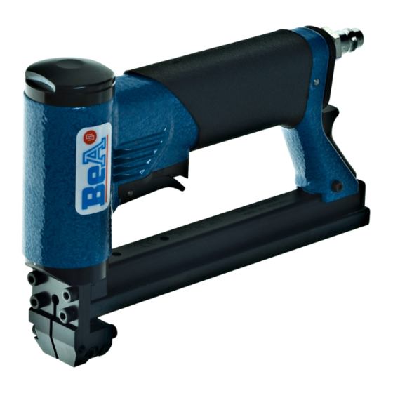
BeA-Druckluftnagler Typ 380/16-400
[1]Abmessungen: L = 210; H = 141 B = 40 mm;
(400L) L = 348; H = 141 B = 40 mm;
[2]Gewicht: 0,97 kg.
[3]Zulässiger Luftdruck: 6 bar,
[4]empfohlener Betriebsdruck: 5 - 6 bar.
[5]Luftverbrauch pro Eintreibvorgang bei 6 bar:
0,3 l freie Luft.
[6]Eintreibgegenstand: BeA-Klammern Typ 380
in den Längen von 6 bis 16 mm.
[7]A-bewerteter Einzelereignis-
L
Schalleistungspegel
[8]A-bewerteterEinzelereignis-
Emission Schalldruckpegel
L
am Arbeitsplatz
pA, 1s
[9]*Vibrationskennwert liegt unter der Deklarations-
grenze
[10] Magazinart: Unterlader
[11] Ladekapazität: min 160 Klammern
(400L) min 320 Klammern
[12] Luftanschluß: 9 bis 10 mm Nennweite
Diese Ersatzteilliste/Servicehinweise bildet mit
dem
beiliegenden
Benutzer-Handbuch
Betriebsanleitung.
Bitte
vor
aufmerksam
lesen
und
Sicherheitshinweise
unbedingt beachten.
Austausch von Verschleißteilen
Achtung:
Gerät von der Pneumatik-Druckquelle
trennen, Klammermagazin entleeren.Die Befestigung
der Kappe muß mit einem Drehschrauber erfolgen, bei
dem das Drehmoment auf 8 Nm eingestellt ist.
Austausch des Treibers
Schraubkappe 14403726 herausdrehen (Bild 1). Das
Gerät umdrehen und durch leichte Schläge auf eine
Holzunterlage die Treiber-Kolbeneinheit vorsichtig
herausklopfen (Bild 2). Die Lagernadel 13300186
mittels Durchschlag soweit heraus-drücken, daß sich
der Treiber auswechseln läßt (Bild 3). Verwenden Sie
die BeA-Hilfsvorrichtung "Montageklotz" 14401089.
Stift mittig in der Bohrung ausrichten. Danach muss die
Bohrung im Kolben auf beiden Seiten leicht verstemmt
werden. Dazu einen Dorn, Durchmesser 3mm, quer
über die Bohrung legen (Bild 3) und mit einem Hammer
auf den Dorn schlagen, so dass die Bohrung leicht
verformt wird.
Auswechseln des Kolben O-Ringes
Siehe Beschreibung "Auswechseln des Treibers", dann
O-Ring 13300158 auswechseln (Bild 3) und mit O-
Ring-Fett 13301706 oder mit BeA-Öl 13301708
einsetzen.
Auswechseln des Puffers
Siehe Beschreibung "Auswechseln des Treibers".
Treiber-Kolbeneinheit
Ausziehvorrichtung 14401109 senkrecht in den
Zylinder führen und den Puffer herausziehen (Abb. 4).
Austausch von Zugfeder und Schubkasten
Sicherungsmutter 13300436 lösen. Zylinderschraube
14403739
und
die
Sperrklinke
(14403721 lang) entfernen. Den Unterschieber nach
hinten aus der Abdeckschiene herausziehen, dann
neue Zugfeder 14400053 (14400185 lang) in den
Schubkasten
haken,
unter
die
Unterschieber nach hinten führen und einhaken (Bild
5).
Auswechseln der Ventil-O-Ringe
Zylinderschraube 13301104 lösen (Bild 6), danach
Ventilabdeckung 14403732 abheben. Kompletten
Ventileinsatz (Bild 7) herausklopfen. Die einem
stärkeren
Verschleiß
unterworfenen
13300011, 13300111 und 13300073 sollten
komplett ausgewechselt werden und mit O-Ring Fett
13301706 oder Öl 13301708 wieder eingesetzt
werden.
BeA Pneumatic Stapler Type 380/16-400
This Spare parts list/service instructions and the
enclosed Operator's Manual constitute the
Operating Instructions. Before using read both
and strictly observe safety instructions.
In the German section of the spare parts list the
technical data are listed under codes [ ] (also see User
Manual).
Service and repair
Attention! Always disconnect the tool from its air
supply and empty magazine before attempting any
repair. Always fix the cap with a torque wrench
adjusted to 8 Nm.
To replace driver blade
Loosen cap 14403726 (fig. 1). Invert machine and tap
gently on wooden surface to remove piston/driver
blade assembly (fig. 2). With a pin punch tap out pin
13300186. Use BeA mounting block 14401089. The
driver blade can then be removed. Replacement of the
blade is a resersal of the above procedure. After
inserting the pin the holes at both sides of the plastic
piston have to be deformed again to prevent movement
of the pin, which can then damage the cylinder. In order
to do this, lay a drift punch, diameter 3mm, across the
hole (fig.3) and hit the punch drift with a hammer so
that the hole is deformed a little bit.
Deutsch
= 87 dB
Wa, 1s
= 82 dB
die
Inbetriebnahme
herausnehmen.
14403740
Umlenkrolle
im
O-Ringe
English
To replace piston O-ring
See instructions "to replace driver blade", then replace
O-ring 13300158 (fig. 3) and grease with BeA grease
13301706 or with BeA oil 13301708 before refitting.
To replace bumper
With the piston/driver assembly removed always
check the bumper. This can easily be removed as in
illustration (4).
To replace feeder bar and tension spring
To release back nose assembly remove safety nut
13300436 and withdraw bolt 14403739. Catch
locking pawl 14403740 (14403721) and spring can
now be removed (fig. 5). Withdraw back nose
assembly. It is now an easy opreation to replace the
tension spring 14400053 (14400185) or feeder bar
(fig. 5). Reassembly is a reversal of the above.
Changing of O-rings on valve system
Remove allen bolt 13301104 to release valve cap
14403732 (fig. 6). Figure 7 shows a breakdown of the
valve components which are accessable once the valve
cap 14403732 has been removed. Replace O-rings
13300011, 13300111 and 13300073 and grease
with BeA O-ring grease 13301706 or oil 13301708
before reasembling.
Agrafeuse pneumatique BeA
Type 380/16-400
Instructions de montage et entretien
Cette Nomenclature des pièces détachées et
instructions
de
montage
et le
l'utilisateur font partie du Mode d'Emploi. Avant
utilisation
veuillez les lire attentivement.
La
partie
en
langue
allemande
caractéristiques techniques avec des références [ ]
(voir manuel d'instruction).
Remplacement de pièces défectueuses:
Attention: avant toute manipulation, débrancher
l'alimentation d'air comprimé et décharger le magasin
de pointes. La fixation du capuchon doit être effectuée
obligatoirement à l'aide d'une clé dynamometrique,
réglée à 8 Nm.
Marteau
Dévisser le capuchon 14403726 (fig. 1), retourner
l'appareil, faire sortir par des légers mouvements de
frappe sur un support en bois l'ensemble piston-
marteau (fig. 2). Chasser l'axe 13300186 avec un
mandrin afin de pouvoir enlever le marteau (fig. 3)
Utiliser l'outil adapté BeA 14401089. Placer la
goupille au centre du trou. Il est ensuite nécessaire
d'aplatir légèrement des deux côtés le trou dans le
piston. Pour cela, poser un mandrin de 3mm de
diamètre en travers du trou (Fig. 3) et taper au marteau
sur le mandrin de manière à déformer un peu le trou.
Joint torique du piston
Suivre d'abord les instructions sous "Marteau", ensuite
remplacer le joint 13300158 (fig. 3). Graisser ou huiler
bien ce joint: graisse 13301706, huile 13301708.
Amortisseur
Suivre d'abord les instructions sous "Marteau", sortir
ensuite l'amortisseur à l'aide de l'outil spécial
14401109 (fig. 4).
Chariot et ressort de traction
Dévisser l'écrou 13300436 enlever la vis 14403739
ainsi que le cliquet 14403740 (14403721) .Retirer
par l'arrière le support d'agrafes, accrocher un nouveau
ressort de traction 14400053 (14400185) au chariot
d'avancement, amener le crochet par le rouleau du
support d'agrafes vers l'arrière et accrocher sur
le têton d'ancrage (fig. 5).
Remplacement des joints de soupape
Dévisser la vis cylindrique 13301104 (fig. 6), enlever
le capuchon de soupape 14403732 (fig. 6). Faire sortir
le bloc complet "soupape" (fig. 7). Les joints toriques
13300011, 13300111 et 13300073 sont soumis à
une forte usure: il est recommandé de les remplacer
aussi souvent que cela est nécessaire, en les graissant
ou en les huilant, graisse 13301706, huile 13301708.
Grapadora neumática BeA tipo 380/16-400
Esta
Lista
de
piezas
e
mantenimiento son partes - junto con las
Instrucciones para el operario - de las normas de
trabajo.
Antes
del
utilizo
detenidamente dichas instrucciones y atender las
instrucciones de seguridad.
En la parte alemana de la lista de repuestos figuran
datos técnicos bajo cifras caracteristicas [ ]. (Véase
también el manual de usuario.)
Cambio de piezas
Importante:
Desconectar
la
alimentación de aire comprimido. Vaciar el cargador
de grapas. Fije la tapa con una llave dinamometrica
ajustada a 8 Nm.
Cambio de la lengüeta
Desenroscar el carril tapa 14403726 (fig. 1). Darle la
vuelta a la máquina y extraer mediante golpes
français
Manuel
de
contient
les
español
instrucciones
de
deben
leerse
máquina
de
la

Manuels Connexes pour BEA 380/16-400


Sommaire des Matières pour BEA 380/16-400
- Page 1 See instructions "to replace driver blade", then replace [1]Abmessungen: L = 210; H = 141 B = 40 mm; O-ring 13300158 (fig. 3) and grease with BeA grease (400L) L = 348; H = 141 B = 40 mm; 13301706 or with BeA oil 13301708 before refitting.
- Page 2 BeA luchtdruktacker Type 380/16-400 completo (fig. 2). Sacar el pasador 13300186 con un punzón, hasta que pueda cambiarse la lengüeta (fig. 3). Utilice el dispositivo auxiliar BeA "Taco de montaje Deze onderdelenlijst en service-instructie vormt 14401089. Centrar el pasador en el agujero.
- Page 3 (kuva 2). Laakerineula 13300186 med lätta slag försiktigt ut pådrivar-kolvenheten på ett träunderlag (bild 2). työnnetään niin pitkälle ulos, että ohjain voidaan vaihtaa (kuva 3). Käytä BeA- Tryck ut lagernålen 13300186 med ett hålslag tills pådrivaren går att byta ut apulaitetta "asennuspölkky"...
- Page 4 (Art.-Nr. 12000021 Standardgerät / Basic model) Type 380/16-400 L (Art.-Nr. 12000026 Standardgerät mit Langmagazin / Basic model with Long magazine) Tipo BeA Gruppe, Bogenstraße 43 - 45, 22926 Ahrensburg/Germany, Telefon +49 (0) 4102 78-0, Telefax +49 (0) 4102 78319 http://www.bea-group.com...