Ndustrio 0G1CP1EC Manuel D'utilisation Et D'installation
Table des Matières
Les langues disponibles
Les langues disponibles
Liens rapides
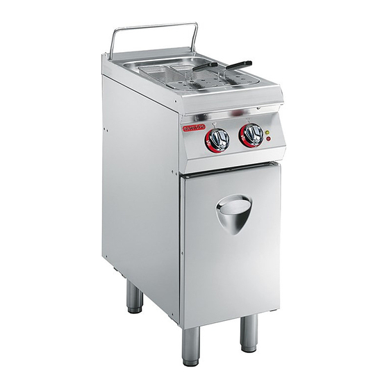
CUOCIPASTA
PASTA COOKER
NUDELKOCHER
CUISEUR À PÂTES
COCEDOR DE PASTA
MANUALE D'USO E INSTALLAZIONE
USE AND INSTALLATION MANUAL
BEDIEN- UND INSTALLATIONSHANDBUCH
MANUEL D'UTILISATION ET D'INSTALLATION
MANUAL DE USO E INSTALACIÓN
0G1CP1EC
0G1CP1E
Italiano
English
Deutsch
Français
Español
Ed.1
05/2013
3143041
IT
GB
DE
FR
ES
Chapitres
Table des Matières

Manuels Connexes pour Ndustrio 0G1CP1EC

Sommaire des Matières pour Ndustrio 0G1CP1EC
-
Page 51: Index Analytique
INDEX réf. chapitres page 1 INFORMATIONS GÉNÉRALES ......... 2 2 INFORMATIONS TECHNIQUES ........3 3 SÉCURITÉ ................. 5 PARTIE 4 UTILISATION ET FONCTIONNEMENT ......6 5 ENTRETIEN ..............10 6 PANNES ................11 7 MANUTENTION ET INSTALLATION ....... 12 8 RÉGLAGES ..............16 PARTIE 9 REMPLACEMENT DE PIÈCES ........ -
Page 52: Informations Générales
INFORMATIONS GÉNÉRALES INFORMATIONS POUR LE LECTEUR Pour retrouver facilement les sujets qui vous inté- partie: elle contient toutes les informations ressent, consulter l’index analytique au début du nécessaires aux destinataires homogènes, manuel. c’est-à-dire tous les opérateurs experts et Ce manuel est divisé en deux parties. autorisés à... -
Page 53: Informations Techniques
F) voyant des thermostats: pour signaler l'inter- vention des thermostats de sécurité (Seulement IDM-39613600100.tif pour la version 0G1CP1EC). 0G1CP1E G)Voyant de réseau: pour signaler l'activation de l'alimentation électrique. H)Porte: pour accéder à la zone interne de l'appa- reil. -
Page 54: Dispositifs De Sécurité
L’illustration indique la position des dispositifs. A)Thermostat de sécurité: bloque l’alimentation électrique dans le cas de surchauffe. Attention 0G1CP1EC Vérifier quotidiennement que les dispositifs de sécurité soient parfaitement installés et ef- ficaces. IDM-39613600200.tif 0G1CP1E IDM-39611700200.tif... -
Page 55: Accessoires Sur Demande
ACCESSOIRES SUR DEMANDE Sur demande l'appareil peut être équipé des acces- soires suivants. A)Couvercle de la cuve CV26 B)Panier C3011 C)Panier C3023 D)"Kit" paniers KCP26 E)Panier C0909 F) Kit pour installation « en pont » (voir page 14) IDM-39603600400.tif SÉCURITÉ NORMES DE SÉCURITÉ... -
Page 56: Normes Pour La Sécurité Sur L'impact Environnemental
NORMES POUR LA SÉCURITÉ SUR L'IMPACT ENVIRONNEMENTAL Chaque organisation a pour but d’appliquer des pro- Sécurité pour l’élimination des déchets d’équi- cédures pour trouver et contrôler l'influence des pro- pements électriques et électroniques (Directive pres activités (produits, services, etc.) DEEE 2002/96/CE) l’environnement. -
Page 57: Description Des Commandes
B)Manette de commande de l’eau: pour remplir la la cuve (Seulement pour la version cuve dans les différents modes. 0G1CP1EC). C)Voyant de réseau: pour signaler l'activation de l'ali- ALLUMAGE ET EXTINCTION DE L’APPAREIL Allumage 1 - Agir sur l'interrupteur sectionneur automatique pour activer le branchement à... -
Page 58: Remplissage Et Vidange De La Cuve
REMPLISSAGE ET VIDANGE DE LA CUVE Remplissage Le remplissage peut être effectué en modes diffé- rents Remplissage rapide libre – Presser et tourner la manette (B) sur 1 pour rem- plir la cuve jusqu’au niveau maximum indiqué par l’indicateur. Le niveau maximum étant atteint, activer les résistan- ces et valider les différents modes de remplissage. -
Page 59: Rétablissement Des Fonctions De L'appareil
1 - Laisser refroidir l'eau de 30-40° C. 2 - Ouvrir la porte (A). 3 - Appuyer sur le bouton (B) du thermostat de sé- curité pour réactiver l'alimentation électrique. 0G1CP1EC 4 - Refermer la porte (A) lorsque l'opération est ter- minée. IDM-39613600300.tif 0G1CP1E IDM-39611700900.tif... -
Page 60: Entretien
– Alimenter l'appareil avec de l’eau à 55°C. Attention – Vider complètement la cuve après emploi. Ne pas utiliser l’appareil sans eau à l'intérieur – L’appareil et les zones environnantes doivent être constamment propres. du récipient pour ne pas provoquer d'endom- magements à... -
Page 61: Pannes
PANNES DÉPANNAGE Avant sa mise en service, l’appareil a été essayé. l’utilisateur, pour tous les autres il faut une compé- Les informations reportées ci-après ont pour but tence technique précise ou des capacités particuliè- d’aider à l'identification et à la correction d’éventuels res;... -
Page 62: Manutention Et Installation
MANUTENTION ET INSTALLATION RECOMMANDATIONS POUR LA MANUTENTION ET L’INSTALLATION Important Effectuer la manutention et l’installation en effectuer ces opérations devra, si nécessai- respectant les informations fournies par le re, organiser un “plan de sécurité” pour fabricant, reportées directement sur l’em- sauvegarder la sécurité... -
Page 63: Mise En Place De L'appareil
MISE EN PLACE DE L’APPAREIL Toutes les phases de mise en place doivent être pri- ses en considération, dès la réalisation du projet gé- néral. Avant de commencer ces phases, outre la définition de la zone de mise en place, celui qui est autorisé... - Page 64 (C), pour interrompre, si nécessaire, l’alimentation de l’eau. En aval de celui- ci, installer des filtres facilement accessibles. Description Valeur 0G1CP1EC Pression 200÷450 kPa (2÷ 4,5 bar) 7÷7.5 Conductivité < 200 mS/cm 9÷13°f (5÷7°d, 6.3÷8.8°e,...
- Page 65 BRANCHEMENT ÉLECTRIQUE (0G1CP1EC) Important Le branchement doit être fait par du person- nel autorisé et qualifié, conformément aux lois en vigueur à ce sujet en utilisant le ma- tériel approprié et prescrit. L'appareil est four- ni avec tension de fonctionnement à 400V/3N, ou sur demande à...
-
Page 66: Réglages
ESSAI DE L’APPAREIL 2 - Vérifier que la tension de réseau corresponde à Important celle de l’appareil. Avant la mise en service, l’essai de l’instal- 3 - Agir sur l’interrupteur sectionneur automatique pour vérifier le branchement électrique. lation doit être fait pour évaluer les condi- 4 - Vérifier le fonctionnement correct des dispositifs tions opérationnelles de chaque composant de sécurité. - Page 83 Puissance Modèle Spannung - Tension Frequenz - Fréquence Strom - Courant Cuba Potencia Modelo Tensión Frecuencia Corriente 0G1CP1EC N.1 (17 l) 9 kW 400 V3~N 50-60 Hz 13 A 0G1CP1EC N.1 (17 l) 9 kW 230 V3~ 50-60 Hz 22,6 A...
- Page 84 Modello Dati elettrici - Electrical data - Daten zur Elektrik Vasca Potenza Model Données électriques - Datos eléctricos Well Power Modelle Becken Leistung Tensione - Voltage Frequenza - Frequency Corrente - Current Cuve Puissance Modèle Spannung - Tension Frequenz - Fréquence Strom - Courant Cuba Potencia...