Table des Matières
Publicité
Liens rapides
CDF
Unitary Package Ducted
Heating Unit
Cooling Unit
INSTALLATION INSTRUCTION MANUAL
MODE D'EMPLOI DE L'INSTALLATION
TABLE OF CONTENTS --- TABLE DES MATIÈRES
COMPONENTS --- COMPOSANTES ...............................................................................................2
ventilation/ du boîtier-manchon et du cabinet de transition
Power & Control Wiring --- Filage pour l'électricité et les commandes
OPERATING INSTRUCTIONS --- CONSIGNES D'UTILISATION ...................................................8
CONTROL SYSTEM DESCRIPTION --- DESCRIPTION DU SYSTÈME DE COMMANDE.............8
OPERATING PROCEDURES --- PROCÉDURES D'EXPLOITATION .............................................9
Suggested Operating Procedures --- Procédures d'exploitation suggérées
Before Each Heating and Cooling Season --- Avant chaque saison de chauffage et de
climatisation
Effective November 1, 1979 (Revision: 02 Date: April 2009) --- En vigueur le 1er novembre 1979 (Révision : 02 Date : Avril 2009)
This manual supersedes all previous issues. --- Le présent manuel a préséance sur tous les documents. 800820
Revised July 2008 --- Révisé en July 2008
---
Colis unitaire avec conduit
---
Chauffage
---
Climatiseur
---
Page
1
Publicité
Table des Matières

Manuels Connexes pour Applied Comfort CDF


Sommaire des Matières pour Applied Comfort CDF
-
Page 1: Table Des Matières
Unitary Package Ducted Colis unitaire avec conduit Heating Unit Chauffage Cooling Unit Climatiseur INSTALLATION INSTRUCTION MANUAL MODE D’EMPLOI DE L’INSTALLATION TABLE OF CONTENTS --- TABLE DES MATIÈRES Page COMPONENTS --- COMPOSANTES ....................2 INSTALLATION --- INSTALLATION....................4 Installation of the Cabinet/Wall Sleeve & Transition Cabinet --- Installation du caisson de ventilation/ du boîtier-manchon et du cabinet de transition Power &... -
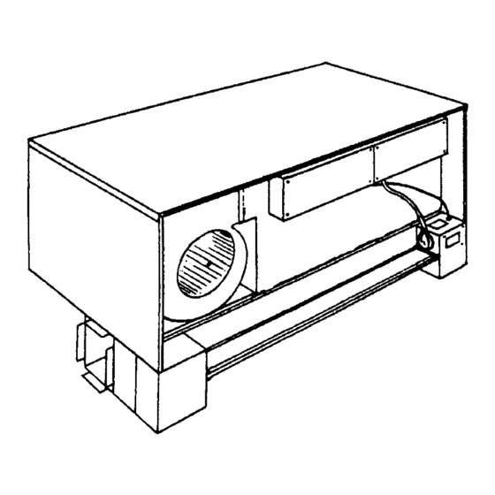
Page 2: Components
COMPONENTS --- COMPOSANTES Heating Cooling Chassis -- Châssis du chauffage et de climatisation Air Flow --- Débit d’air Air Filter --- Filtre à air Air Flow --- Débit d’air Outside Surface of Finished Wall --- Surface extérieure d’un mur fini Outdoor Louver --- Déflecteur extérieur Inside Surface of Finished Wall ---Surface intérieure d’un mur fini... - Page 3 If the unit is ducted out both sides, size the duct for the anticipated fraction of the 325 CFM pertaining to that branch. In other words, if the unit is ducted out of both sides, and 40% airflow is desired out of the left side and 60% out the left, then size the duct as follows: 40/100 X 325 = 130 CFM at .15”...
-
Page 4: Installation
INSTALLATION --- INSTALLATION Mansory Wall -- Mur de brique Panel Wall --- Panneau mural Minimum --- Minimum Caulking --- Calfeutrage Concrete --- Ciment Concrete Pad --- Plateforme cimentée Normal Floor construction --- Construction normale d’un plancher INSTALLATION OF THE CABINET/WALL SLEEVE & TRANSITION CABINET 1. -
Page 5: Installation Du Caisson De Ventilation/ Du Boîtier-Manchon Et Du Cabinet De Transition
13. Build up wall around cabinet, making sure that the cracks are closed and that the cabinet remains square, especially on the top. B. Existing Masonry Wall Cut opening into wall, providing a minimum of ½” clearance on sides and top and 1” on the bottom, to pour new base (12”... -
Page 6: Power & Control Wiring
Suivre les étapes 1, 2, 5, 6, 7 et 8 pour la nouvelle maçonnerie. C. Nouveau panneau de façade Installer un socle de béton de 12" (30 cm) sous l’appareil. Suivre les étapes 1, 2, 5, 6, 7 et 8 pour la nouvelle maçonnerie. D. -
Page 7: Filage Pour L'électricité Et Les Commandes
18. CAUTION: One side of the unit’s 24-volt control system is grounded. When wiring thermostat, care must be taken not to ground the red wire. -- -- -- -- -- FILAGE POUR L’ÉLECTRICITÉ ET LES COMMANDES 1. Brancher le cordon d’alimentation de l’appareil aux bons terminaux de la prise. 2. -
Page 8: Operating Instructions
8. Brancher le faible faisceau de câblage au châssis de chauffage-refroidissement. 9. Brancher le châssis de chaufface/ climatisation dans la prise d’alimentation électrique sur le recouvrement du conduit. 10. Installer le filtre à air de l’appareil en place. 11. Installation du panneau avant. 12. -
Page 9: Description Du Système De Commande
To get reasonable comfort and energy consumption, it is recommended that wall mounted thermostats be set at 21°C (70°F) for heating and 25°C (77°F) for cooling. Over-adjusting the thermostat will not increase the rate at which a unit will heat or cool the space. -- -- -- -- -- Cet appareil autonome de chauffage et de refroidissement a été... -
Page 10: Procédures D'exploitation Suggérées
IF THE UNIT DOESN’T WORK The unit has been carefully designed and tested and should provide trouble free operation when properly sized, correctly installed, intelligently operated and checked by a competent serviceman at least once a year. However, if you should experience difficulty, check the following before calling for services. 1. -
Page 11: Before Each Heating And Cooling Season
PREVENTATIVE MAINTENANCE --- MAINTENANCE PRÉVENTIVE CAUTION: DISCONNECT POWER SUPPLY TO UNIT BEFORE REMOVING FRONT PANEL. BEFORE EACH HEATING AND COOLING SEASON: 1. Remove front panel and disconnect control wiring. 2. Clean front surfaces with vacuum cleaner and damp cloth. 3. Remove grounding screws (see fig. 5) and pull out chassis. 4.