Publicité

Les langues disponibles

Les langues disponibles

Liens rapides

Montage- und Bedienungsanleitung
GB INSTALLATION AND OPERATING INSTRUCTIONS
F
INSTRUCTIONS DE MONTAGE ET MODE D'EMPLOI
I
INSTRUZIONE PER IL MONTAGGIO E L'USO
EuroJet
1

Publicité

Table des Matières
loading

Sommaire des Matières pour UWE JetStream Eurojet

  • Page 1 Montage- und Bedienungsanleitung GB INSTALLATION AND OPERATING INSTRUCTIONS INSTRUCTIONS DE MONTAGE ET MODE D’EMPLOI INSTRUZIONE PER IL MONTAGGIO E L’USO EuroJet...
  • Page 2 Inhaltsverzeichnis MONTAGE UND BEDIENUNGSANLEITUNG ........Seite 3 - 15 GB Table of Contents INSTALLATION AND OPERATING INSTRUCTIONS ......page 16-27 Contenu INSTRUCTIONS DE MONTAGE ET MODE D’EMPLOI ....... page 28-39...
  • Page 3: Table Des Matières

    SICHERHEITSHINWEISE 1.1 Vor der Inbetriebnahme Die Sicherheitshinweise und die Bedienungsanleitung müssen vor der Aufstellung und Inbetriebnahme auf- merksam gelesen und beachtet werden. Halten Sie unbedingt die Anforderungen der Firma uwe bzw. der Normgeber ein. 1.2 Erstinbetriebnahme des Gerätes Vor jeder Inbetriebnahme sind die örtlichen Sicherheitsbestimmungen sowie die Sicherheitshinweise einzuhal- ten.
  • Page 4: Bestimmungsgemäße Verwendung

    Anforderungen an die entsprechende elektrische Installation entnehmen Sie bitte dem im Heft aufgeführten Abschnitt 7 „ An den Elektroinstallateur “. Teile der Einrichtung, die unter Spannung stehende Teile enthalten, müssen für Personen, die das Bad benutzen, unzugänglich sein. Geräte und Geräteteile, welche elektrische Bauteile enthalten, müssen so aufgestellt bzw.
  • Page 5: Einsetzen Des Düsenmantelgehäuses In Die Schalung

    EINSETZEN DES DÜSENMANTELGEHÄUSES IN DIE SCHALUNG • Montage (Bild 1) Schrauben Sie das Düsenmantelgehäuse so in die Schalung, daß das rote Schild mit Text „oben“ nach oben zeigt. Funktion Dann befindet sich, von der Beckeninnenseite her gesehen, der Druckstutzen auf der senkrechten Mittelachse über dem Gehäusemittelpunkt, der Saugstutzen rechts unten, der Luftansaugschlauch links oben.
  • Page 6 • Fliesenplan (Bild 2) Fliesen Sie das Düsenmantelgehäuse bis zu seiner Innenkante. • Becken mit Folienauskleidung (Bild 3) Ordnen Sie Klemmrahmen, die Dichtungen aus Folienmaterial und die Gummidichtung nach Bild 3 an. Klemmring Dichtung vor und hinter der Folie Fliesen bis je eine Dichtung aus zur Innenkontur Folienmaterial...
  • Page 7 Einbau des Düsenmantelgehäuses in ein Stahl-, Alu- und Polyesterbecken Luftansaugschlauch zur Ansaugung der Luft aus dem Beckenumgang 5-10 cm über dem Wasserspiegel Wasserspiegel Wasserspiegel oben Luft- 45° schlauch Kabelschutz- schlauch Lage der Düse Klemmrahmen Dichtung Senkschraube Ø 0,9 M 8x35 Ausschnitt und Saug- Bohrungen in der...
  • Page 8: Fertigmontage/Angaben Nur Für Autorisierte Personen

    Die Sicherheitshinweise müssen vor der Aufstellung aufmerksam gelesen werden. Halten Sie unbedingt die An- forderungen der Fa. uwe bzw. der Normgeber ein. Für den Fall, daß die Hinweise nicht berücksichtigt werden, geschieht dies in der alleinigen Verantwortung des Monteurs. Jegliche Haftung des Herstellers entfällt somit.
  • Page 9 Steuerkasten oberhalb des Wasserspiegels montieren Anschluss Steuerkasten (Bild 5) Der Steuerkasten (18) sollte entweder in einem trockenen Umgang oder in einem angrenzenden Raum unterge- bracht werden. Der Anschluss ist sorgfältig nach DIN VDE 0100 Teil 702 auszuführen. Der Anschluss an das Netz erfolgt durch eine 5 G 2,5 mm²...
  • Page 10: Vor Der Inbetriebnahme

    Vor jeder Inbetriebnahme sind die örtlichen Sicherheitsbestimmungen sowie die Sicherheitshinweise einzuhalten. Ist das Gerät komplett montiert und elektrisch angeschlossen, kann das Gerät in Betrieb genommen werden. Bevor Sie die uwe JetStream Anlage in Betrieb nehmen, drehen Sie den Motor am Lüfterrad von Hand mehrmals durch.
  • Page 11: Start

    4.3 Start Zum Schwenken der Strahldüse Pumpe abschalten. Warnung Wenn Sie den Pneumatik-Schalter (1) drücken, wird die Anlage EIN bzw. AUS geschaltet. Bei Verwendung eines wassergeschützten Lichttasters, der bauseits zu stellen ist, können Sie das Pumpenaggregat auch von einem anderen Ort aus schalten. Die Düse ist in jede Richtung mit einem Winkel von 30° einstellbar. Bei Einstellung der Düse muss die Pumpe unbedingt ausgeschaltet sein.
  • Page 12: Gegenstromschwimmen

    Strömung direkt unterhalb des Wasserpegels erzeugt wird, ohne grosse Oberflächenwirbel zu verursa- chen. 4.7 Überwintern Wenn die JetStream EuroJet frostgefährdet ist, wird empfohlen den Wasserpegel des Schwimmbeckens un- terhalb der Ansaugung zu bringen. Entfernen Sie die Wasserablaufmutter am unteren Teil der Pumpe. Nach dem Wasserablauf die Mutter nicht wieder montieren Warnung 4.8 Wiederinbetriebnahme...
  • Page 13: Montage Der Haltegriffe

    MONTAGE DER HALTEGRIFFE Montage in Betonbecken mit Putz oder Montage Fliesenauskleidung Obere Halteseildeckel wie vermaßt verschrauben. Untere Haltseildeckel leicht nach unten ziehen, so daß sich das Halteseil gerade richtet. Schraubenlöcher abbohren und Deckel verschrauben. Halteseildeckel gestrichelte Halteseil- deckel Schrauben werden nur für Ø...
  • Page 14: An Den Elektroinstallateur

    Teil 702 aus. Halten Sie unbedingt die Sicherheitshinweise und die Anforderungen der Norm- Warnung geber ein. Alle Arbeiten an den stationären Schwimmbeckenpumpen dürfen nur durch von der Fa uwe autorisierten Firmen oder durch geschulte Elektrofachkräfte durchgeführt werden. Die DIN VDE und zutreffenden Unfallverhütungsvorschriften sind bei Arbeiten mit Spannung zu beachten.
  • Page 15 Schaltplan für JetStream Schaltplan für JetStream EuroJet, BAMBO2, BAMBO, COCO EuroJet, BAMBO2, BAMBO, COCO (unbeleuchtete Ausführung) (unbeleuchtete Ausführung) LIBRA 3-5, LIDO, LIDO2, VIVA LIBRA 3-5, LIDO, LIDO2, VIVA mit Pneumatikschalter mit Pneumatikschalter und Zeitrelais 3 N ~ PE 50 Hz 400/230 V 16 A...
  • Page 16: Safety Instructions

    1.1 Before Setting into Operation Before installation and setting into operation, the Safety Instructions and the Operating Instructions must be carefully read and observed. You must definitely comply with the requirements of the uwe company and of the standards authorities.
  • Page 17: Proper Operation

    Therefore, you must definitely observe the following Safety Instructions: The JETSTREAM has substantial power. Before massage, you must definitely reduce the Warning pressure. Do not utilize full thrust against soft parts of the body. Switch off pump before adjusting angle of nozzle. For large-area massage, reduce the strength to half thrust.
  • Page 18: Installing The Wall Niche In Concrete Shuttered Pools

    INSTALLING THE WALL NICHE IN CONCRETE SHUTTERED POOLS Installation (fig. 1) Position the wall niche ensuring that the read label “Oben” (top) is on top. Function Viewed from inside the pool, the suction duct is on the vertical middle axis above the center of the housing, the pressure duct at the bottom on the right side.
  • Page 19 Installing the wall niche in steel, aluminium and polyester pools air inlet tube for air suction end part to be water level water level installed 5 - 10 cm above water level 45° label air inlet protective sleeve for pneumatic tube nozzle center line clamping frame gasket...
  • Page 20: Final Assembly Instrucions

    The safety instructions must be read carefully before installation. You must definitely fulfil the requirements stated by the uwe company and by the standars authorities. If the instructions are not observed, the installation engineer shall bear the sole responsibility. The manufacturer shall thus be absolved of any liability.
  • Page 21 Install the control panel higher than the water level Mounting the control panel The control panel must not be installed in a chamber. It should be accommodated either in a dry walkway behind the pool wall or in an adjacent room. The connection must be effected carefully in accordance with EN 60335-2- 41.
  • Page 22: Operation / Information For The User Of The Unit

    JetStream EuroJet Installation in concrete pools dimensions in cm OPERATION / INFORMATION FOR THE USER OF THE UNIT 4.1 Before starting Safety precautions and operating instructions must be carefully read and observed before setting up and operating. 4.2. First time operation Before operating, local safety requirements must be met and safety precautions must be observed.
  • Page 23: Starting The Unit

    4.3 Starting the unit Before swivelling the nozzle, switch off the pump. Warning When you press the pneumatic button (1), this switches the unit ON or OFF. When using a separate waterproof switch for remote control the unit can also be operated from outside the pool. The nozzle (6) can be swivelled in any direction within a cone of about 30°.
  • Page 24: Swimming Against The Current

    When repairing or bringing into operation again, ensure that tampering has not occured. The unit is only to be serviced by authorized persons. Do not conduct any work which might Warning have impair on the safety of the unit. Only buy original spares from your dealer or uwe.
  • Page 25: Fitting Instruction For Handgrips

    FITTING INSTRUCTIONS FOR HANDGRIPS Fitting in concrete shuttered pools Mounting: Fix upper end cap to pool wall as shown. Pull down lower cap to staighten rope. Drill holes for lower cap and screw into position. end cap broken screw are only needed end cap for prefab.
  • Page 26: Information For The Electrician

    Warning authorities. All work on the pool pump may be performed only by firms having authorisation from the uwe company, or by trained electrical experts. The EN regulations and the relevant accident prevention regulations must be observed in all work where voltage is present.
  • Page 27 Wiring diagramm for JETSTREAM EuroJet, BAMBO2, BAMBO, COCO Wiring diagramm for JETSTREAM, EuroJet, BAMBO2, BAMBO, COCO (versions without illumination), JUNO, LIBRA 3-5, LIDO, LIDO 2, VIVA (versions without illumination), JUNO, LIBRA 3-5, LIDO, LIDO 2, with pneumatic switch 3N ~ PE 400 V...
  • Page 28: Instructions De Securite

    1.1 Avant la mise en service Les instructions de sécurité et le mode d’emploi doivent être lus attentivement avant l’installation et la mise en service et respectés impérativement. Conformez-vous exactement aux instructions de la société uwe et aux différentes normes en vigueur.
  • Page 29: Utilisation Correcte De L'appareil

    Il est donc impératif de respecter les instructions de sécurité ci-après : Le jet de la buse produit une énergie considérable. Réduisez ainsi impérativement la pression du jet avant tout massage. Attention Ne pas diriger le jet de massage dans toute sa puissance sur les parties sensibles du corps. Arrêter la pompe avant de faire pivoter la buse orientable.
  • Page 30: Montage De La Pièce À Sceller Dans Le Coffrage

    MONTAGE DE LA PIÈCE À SCELLER DANS LE COFFRAGE • Montage (fig. 1) Positionner la pièce à sceller dans le coffrage de telle manière que l’étiquette rouge „haut“ (Oben) se trouve en haut. Fonction Vu de l’intérieur du bassin,le tuyau de refoulement se trouve alors sur l’axe vertical au-dessus du centre du boîtier, le tuyau d’aspiration se trouve en bas à...
  • Page 31 Montage de la pièce à sceller dans piscines d’ acier, d’ aluminium et de revêtement Polyester tuyau d' aspiration d' air pour aspiration d' air, extremité à placer niveau de l' eau niveau de l' eau 5-10 cm au-dessus du niveau d' eau haut tuyau "oben"...
  • Page 32: Instructions Pour Montage Final

    Les Instructions de sécurité doivent être lues attentivement avant l’installation. Conformez-vous exactement aux instructions données par la société uwe et aux différentes normes en vigueur. En cas de non-respect de ces instructions, l’utilisateur est seul tenu responsable. Le constructeur est alors dégagé de toute responsabilité.
  • Page 33 Coffret électrique et au dessus de la surface de l’eau. Raccordement du coffret électrique. Le coffret électrique ne doit pas être implanté dans un lieu humide. Il est à placer soit dans un endroit sec soit dans une pièce avoisinante. Effectuez le raccordement en respectant les normes en viguer, notamment les nor- mes DIN VDE 0100 partie 702 et les normes C 15.100.
  • Page 34: Mise En Service Informations Destinées À L'utilisateur

    EuroJet Montage dans piscines béton mesures en cm MISE EN SERVICE INFORMATIONS DESTINÉES À L’UTILISATEUR 4.1 Avant la mise en service Les instructions de sécurité et le mode d’emploi doivent être lus attentivement avant l’installation et la mise en service de l’appareil. 4.2 Première mise en service de l’appareil Il est impératif d’observer les prescriptions locales de sécurité...
  • Page 35: Mise En Marche

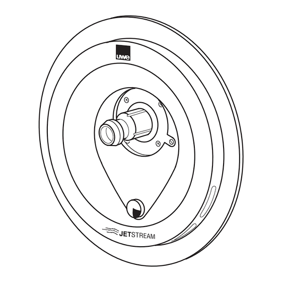
    4.3 Mise en marche Arrêtez la pompe avant de faire pivoter la buse orientable Attention Pressez le poussoir pneumatique (1) pour mettre en marche ou à l’arrêt l’installation. La buse (3) peutêtre pivotée dans une angle d’environ 30°dans toutes les directions. 4.4 Puissance du jet Attention ! Le jet de la buse produit une énergie considérable.
  • Page 36: Nage À Contre-Courant

    Seuls les personnes autorisées à cet effet ont le droit d’effectuer des travaux sur l’appareil. Toute opération préjudiciable à la sécurité de l’appareil doit être évitée. Utiliser uniquement les pièces de rechange d’origine distribuées par votre revendeur ou la société uwe.
  • Page 37: Conseils Pour Montage Des Poignées De Soutien

    CONSEILS POUR MONTAGE DES POIGNÉES DE SOUTIEN MONTAGE a) Béton b) Bassin préfabriqué Monter d’abord le capot de fixation supérieur Pour le perçage des 5 trous: à l’aide des chevilles scéllées et des vis TF s’aider soit du croquis ci - contre (si bassin avec liner ne pas oublier le joint soit des joints de fixation caoutchouc)
  • Page 38: L'attention De L'électricien

    Attention prescriptions des différentes normes en vigueur. Seuls des électriciens spécialisés sont autorisés à effectuer des travaux sur les pompes uwe Jetstream. Les normes en vigueur, les normes DIN VDE et UTE ainsi que les instructions de prévention applicables contre les accidents sont à respecter lors de travaux sous tension.
  • Page 39 Plan électrique uwe JETSTREAM pour EuroJet, BAMBO2 , BAMBO , Plan électrique uwe JETSTREAM pour EuroJet, BAMBO2 , BAMBO , COCO, (sans lumière) LIBRA 3-5, LIDO, LIDO2, VIVA avec commande COCO, (sans lumière) LIBRA 3-5, LIDO, LIDO2, VIVA avec commande...
  • Page 40 GmbH Buchstraße 82 · Postfach 2020 D-73510 Schwäbisch Gmünd Tel. (07171) 103 -0 · Fax (07171) 103 -106...

Table des Matières