Table des Matières

Publicité

Les langues disponibles
  • FR

Les langues disponibles

Liens rapides

Bedienungsanleitung
DE
Operating manual
EN
Mode d'emploi
FR
thermio™ essential smart
2
Manuale operativo
IT
35
Instrucciones de
ES
manejo
67
99
131

Publicité

Table des Matières
loading

Sommaire des Matières pour Intermatic GRASSLIN thermio

  • Page 1 Bedienungsanleitung Manuale operativo Operating manual Instrucciones de manejo Mode d'emploi thermio™ essential smart...
  • Page 2 Diese Anleitung ermöglicht den sicheren und effizienten Umgang mit dem Raumthermostat "thermio™ essential smart" (im Folgenden "Gerät"). Diese Anleitung ist Bestandteil des Geräts und muss für jeden, der mit dem Gerät umgeht, jederzeit zugänglich aufbewahrt werden. Jeder, der mit dem Gerät umgeht, muss diese Anleitung vor Beginn aller Arbeiten sorgfältig durchge- lesen und verstanden haben.
  • Page 3 Das Urheberrecht liegt beim Hersteller. © Grässlin GmbH Bundesstr. 36 78112 St. Georgen DEUTSCHLAND Download www.graesslin.de : Folgende Informationen finden sich unter • Konformitätserklärung • Anleitung zum Download • Technische Daten...
  • Page 5: Table Des Matières

    Übersicht....................7 Aufbau und Funktion......................7 Sicherheit..................... 11 Installation.................... 13 Montage auf eine Unterputzdose..................14 Aufputzmontage........................18 Heizzyklus einstellen......................20 Hysterese einstellen......................23 Bedienung.................... 26 Bluetooth einschalten......................26 Raumthermostat über mobile Geräte programmieren und bedienen........27 Soll-Temperatur einstellen....................29 Uhrzeit einstellen........................ 30 Tastensperre einschalten....................
  • Page 6 Raumthermostat in den Stand-by-Betrieb versetzen............31 Entsorgung................... 33...
  • Page 7: Übersicht

    Übersicht Aufbau und Funktion Abb. 1: Übersicht thermio™ essential smart...
  • Page 8 Stand-by-Betrieb Uhrzeit anzeigen Kipptaster Schaltdifferenz-Symbol Set-Symbol Taste oben Anzeige für Soll- und Ist-Temperatur Batterie-Symbol Taste unten Perioden pro Tag Bluetooth-Symbol Kabeldurchführung Reset-Taste...
  • Page 9 Funktionsbeschreibung Das Raumthermostat "thermio™ essential smart" ist ein digitales Thermostat und dient zur Tempera- turregelung von Heizsystemen in geschlossenen Räumen. Das Raumthermostat verfügt über eine Blue- tooth-Funktion und kann über ein mobiles Gerät programmiert werden. Die Reichweite zwischen mobilem Gerät und dem Raumthermostat beträgt maximal 10 Meter (abhängig von den Räumlichkeiten). Wenn das Thermostat über den Temperaturfühler einen Temperaturabfall erkennt, wird das Heizsystem eingeschaltet und nach Erreichen der Soll-Temperatur wieder ausgeschaltet.
  • Page 10 Regelart Abb. 2: Kurzschlussbrücke Die Kurzschlussbrücke (Abb. 2/1) ist eine Brücke, die zwei Stifte (Kontakte) elektrisch verbindet. Die Kurzschlussbrücke kann auf zwei verschiedene Positionen (2-Punkt- und PID-Position) gesteckt werden, abhängig von der gewünschten Funktion. In der Werkseinstellung steckt die Kurzschlussbrücke auf der PID-Position (Abb.
  • Page 11: Sicherheit

    Sicherheit Bestimmungsgemäße Verwendung • Das Raumthermostat dient ausschließlich zur Temperaturregelung (+5 °C bis +35 °C) von Heizsys- temen in geschlossenen Räumen. Zur bestimmungsgemäßen Verwendung gehört auch die Einhaltung aller Angaben in dieser Anleitung. Jede über die bestimmungsgemäße Verwendung hinausgehende oder andersartige Benutzung gilt als Fehlgebrauch.
  • Page 12 Verletzungsgefahr bei falschem Umgang mit Batterien! Bei falschem Umgang mit Batterien besteht die Gefahr, dass die Batterien explodieren oder dass gesundheitsschädliche Flüssigkeit aus den Batterien WARNUNG! austritt. − Niemals Batterien beschädigen oder deformieren. − Niemals die Kontakte (Plus- und Minuspol) der Batterien kurzschließen. −...
  • Page 13: Installation

    Installation Aufstellort Um eine fehlerfreie Messung des Raumthermostats zu gewährleisten, den Aufstellort richtig wählen. Abb. 3: Anforderungen an den Aufstellort...
  • Page 14: Montage Auf Eine Unterputzdose

    Montage auf eine Unterputzdose Personal: • Elektrofachkraft Montageplatte montieren Montageplatte mit Schrauben (3,5 x 25 mm) auf die Unterputzdose montieren (Abb. 6). Der Pfeil (Abb. 6/1) auf der Montageplatte muss nach oben zeigen. Gehäusedeckel demontieren Die Schraube am Gerätegehäuse mit dem Kreuzschlitzschraubendreher lösen und den Gehäusede- ckel demontieren.
  • Page 15 Abb. 4: Anschlussplan Ein- und Ausschalter COM (Wechselkontakt, gemeinsamer Leiter Kontakt) NC (Ruhekontakt, Öffner Kontakt) NO (Arbeitskontakt, Schließer Kontakt)
  • Page 16 Die Anschlussleitungen anhand des Anschlussplans (Abb. 4) in die entsprechende Klemme ein- führen und festdrehen. Batterie einlegen Abb. 5: Batterie einlegen Die 2 Alkalibatterien vom Typ 1,5 V AA LR6 mit richtiger Polung (Abb. 5) in den Gehäusedeckel einlegen.
  • Page 17 Gehäuseboden montieren Abb. 6: Gehäuseboden auf Montageplatte montieren Montage auf eine Unterputzdose ohne Dübel mit Montageplatte Aufputzmontage ohne Montageplatte mit Dübel Den Gehäuseboden des Geräts mit den Schrauben (3 x 6 mm) auf die Montageplatte montieren (Abb. 6).
  • Page 18: Aufputzmontage

    Gehäuse schließen Den Gehäusedeckel auf den Gehäuseboden setzen und die Schraube am Gerätegehäuse mit dem Kreuzschlitzschraubendreher festdrehen. Aufputzmontage Personal: • Elektrofachkraft Gehäusedeckel demontieren Die Schraube am Gerätegehäuse mit dem Kreuzschlitzschraubendreher lösen und den Gehäusede- ckel demontieren. Das Lochbild vom Gehäuseboden an die Wand übertragen und an den markierten Positionen Löcher bohren (5-mm-Durchmesser und mindestens 25 mm tief).
  • Page 19 Die Anschlussleitungen anhand des Anschlussplans (Abb. 4) in die entsprechende Klemme ein- führen und festdrehen. Gehäuseboden montieren Den Gehäuseboden mit den Schrauben (3,5 x 25 mm) an den Wanddübeln befestigen. Batterie einlegen Die 2 Alkalibatterien vom Typ 1,5 V AA LR6 mit richtiger Polung (Abb. 5) in den Gehäusedeckel einlegen.
  • Page 20: Heizzyklus Einstellen

    Heizzyklus einstellen Auswahl des Heizzyklus Die Anzahl der Wärmemessungen kann auf 3, 6, 9 oder 12 Mal pro Stunde (Werkseinstellung: 6 Mal pro Stunde) eingestellt werden. In der Werkseinstellung steckt die Kurzschlussbrücke auf der PID-Position. Auf dieser Position kann der Heizzyklus eingestellt werden. Wenn die Kurz- schlussbrücke auf der 2-Punkt-Position steckt, kann die Hysterese eingestellt werden.
  • Page 21 • Elektrofachkraft Kurzschlussbrücke einstellen Die Schraube am Gerätegehäuse mit dem Kreuzschlitzschraubendreher lösen. Abb. 7: Kurzschlussbrücke anheben Die Kurzschlussbrücke (Abb. 7/1) im Gehäusedeckel mit einem Schlitzschraubendreher anheben. Die Kurzschlussbrücke (Abb. 7/1) auf die PID-Position (Abb. 7/3) stecken. Gehäuse schließen...
  • Page 22 Den Gehäusedeckel auf den Gehäuseboden setzen und die Schraube am Gerätegehäuse mit dem Kreuzschlitzschraubendreher festdrehen. Die Kurzschlussbrücke steht auf der PID-Position, nun kann der Heizzyklus eingestellt ð werden. Die Reset-Taste (Abb. 1/13) drücken, um das Display zurückzusetzen. Heizzyklus einstellen Zum Einstellen des Heizzyklus die Taste oben (Abb. 1/6) und die Taste unten (Abb. 1/9) gleichzeitig 5 Sekunden gedrückt halten.
  • Page 23: Hysterese Einstellen

    Hysterese einstellen Auswahl der Hysterese Die Kurzschlussbrücke kann auf zwei verschiedene Positionen (2-Punkt-Posi- tion und PID-Position) gesteckt werden, abhängig von der gewünschten Funktion. In der Werkseinstellung steckt die Kurzschlussbrücke auf der PID-Position. Auf dieser Position kann der Heizzyklus eingestellt werden. Wenn die Kurz- schlussbrücke auf der 2-Punkt-Position steckt, kann die Hysterese eingestellt werden.
  • Page 24 Personal: • Elektrofachkraft Kurzschlussbrücke einstellen Die Schraube am Gerätegehäuse mit dem Kreuzschlitzschraubendreher lösen. Abb. 8: Kurzschlussbrücke anheben Die Kurzschlussbrücke (Abb. 8/1) im Gehäusedeckel mit einem Schlitzschraubendreher anheben. Die Kurzschlussbrücke (Abb. 8/1) auf die 2-Punkt-Position (Abb. 8/2) stecken.
  • Page 25 Gehäuse schließen Den Gehäusedeckel auf den Gehäuseboden setzen und die Schraube am Gerätegehäuse mit dem Kreuzschlitzschraubendreher festdrehen. Die Reset-Taste (Abb. 1/13) drücken, um das Display zurückzusetzen. Hysterese einstellen Zum Einstellen der Hysterese die Taste oben (Abb. 1/6) und die Taste unten (Abb. 1/9) gleichzeitig 5 Sekunden gedrückt halten.
  • Page 26: Bedienung

    Bedienung Bluetooth einschalten Personal: • Benutzer Den Kipptaster (Abb. 1/3) nach oben drücken und gleichzeitig die Taste oben (Abb. 1/6) drücken. ð Das Bluetooth-Symbol (Abb. 1/11) wird im Display angezeigt.
  • Page 27: Raumthermostat Über Mobile Geräte Programmieren Und Bedienen

    Raumthermostat über mobile Geräte programmieren und bedienen App herunterladen Das Raumthermostat kann über ein mobiles Gerät programmiert werden. Diese Funktionen sind über die mobilen Geräte programmierbar: Grundeinstellungen • Manuell ein-/ausschalten • Offset definieren und anpassen • Temperatureinheit auswählen • Passwort vergeben •...
  • Page 28 • Temperatur halten (Hold on) Weiterführende Informationen Die App für "thermio essential smart" ist sowohl für Android- als auch für iOS-Geräte verfügbar und im jeweiligen Store erhältlich. Für detaillierte Beschreibungen zu Sender und Empfänger siehe die entspre- chende Online-Bedienungsanleitung. QR-Code für den App-Download (http://qrc.graesslin.de/801014757/app) QR-Code für die Online-Bedienungsanleitung (http://qrc.graesslin.de/801014757)
  • Page 29: Soll-Temperatur Einstellen

    Soll-Temperatur einstellen Personal: • Benutzer Den Kipptaster (Abb. 1/3) nach oben oder nach unten drücken, um das Heizsystem anzusteuern. Der Kipptaster fällt auf die Ausgangsstellung zurück. ð Zum Einstellen der Soll-Temperatur die Taste oben (Abb. 1/6) oder die Taste unten (Abb. 1/9) 2 Mal kurz nacheinander drücken.
  • Page 30: Uhrzeit Einstellen

    Das Einstellen der Soll-Temperatur auf einen höheren Wert beschleunigt nicht das Aufheizen des Raums. Die Aufheizge- schwindigkeit wird ausschließlich durch die Bedingungen im Heizsystem bestimmt. Uhrzeit einstellen Das Raumthermostat muss einmal mit einem mobilen Gerät verbunden sein, danach wird die Uhrzeit automatisch übernommen.
  • Page 31: Tastensperre Einschalten

    Tastensperre einschalten Personal: • Benutzer Zum Einschalten der Tastensperre den Kipptaster (Abb. 1/3) nach unten und gleichzeitig die Taste oben (Abb. 1/6) drücken. Die Tastensperre ist eingeschaltet und am Gerät kann nichts mehr geändert werden. ð Raumthermostat in den Stand-by-Betrieb versetzen Personal: •...
  • Page 32 Frostschutzfunktion Das Gerät hält die Raumtemperatur auf 5 °C. Das Heizsystem wird automatisch eingeschaltet, wenn die Raumtemperatur unter 5 °C sinkt.
  • Page 33: Entsorgung

    Entsorgung Unsachgemäße Entsorgung Gefahr für die Umwelt durch falsche Entsorgung! Durch falsche Entsorgung können Gefahren für die Umwelt entstehen. − Elektroschrott und Elektronikkomponenten fachgerecht entsorgen, d. h. UMWELTSCHUTZ! getrennt nach Materialgruppen der zu entsorgenden Teile. − Batterien/Akkumulatoren (Richtlinie 2006/66/EG) und Elektro- oder Elek- tronikschrott keinesfalls mit dem Restmüll entsorgen.
  • Page 35 This manual ensures safe and efficient use of the “thermio™ essential smart” room thermostat (referred to as “device” in the following). This manual is a component of the device and must remain accessible at all times for everyone who uses the device. Everyone who uses the device must have read and understood this manual before commencing any work.
  • Page 36 © Grässlin GmbH Bundesstr. 36 78112 St. Georgen GERMANY Download www.graesslin.de : You can find the following information at • Declaration of conformity • Download instructions • Technical data...
  • Page 37 Overview....................39 Design and function......................39 Safety....................43 Installation.................... 45 Installation in a flush-mounted socket................. 46 On-wall mounting....................... 50 Setting the heating cycle..................... 52 Setting the hysteresis......................55 Operation..................... 58 Switching on the Bluetooth....................58 Programming and operating the room thermostat using mobile devices......59 Setting the temperature setpoint..................
  • Page 38 Putting the room thermostat into stand-by mode..............63 Disposal....................65...
  • Page 39: Overview

    Overview Design and function Fig. 1: Overview of thermio™ essential smart...
  • Page 40 Stand-by mode Display time Toggle key Switching differential symbol Set symbol Top button Display for setpoint and current temperature Battery symbol Bottom button Periods per day Bluetooth symbol Cable feed-through Reset button...
  • Page 41 Description of function The “thermio™ essential smart” room thermostat is a digital thermostat and is used for regulating the temperature of indoor heating systems. The room thermostat has a Bluetooth function and can be pro- grammed from a mobile device. The connection range between the mobile device and the room thermo- stat is a maximum of 10 metres (depending on the premises).
  • Page 42 Control type Fig. 2: Jumper The jumper (Fig. 2/1) is a bridge that electrically connects the two pins (contacts). The jumper can be inserted in two different positions (2-point and PID position), depending on which function is desired. In the factory setting, the jumper is inserted in the PID position (Fig. 2/3).
  • Page 43: Safety

    Safety Intended use • The room thermostat may only be used for regulating the temperature (+5°C to +35°C) of heating systems in enclosed spaces. The intended use also includes compliance with all information specified in this manual. Any use other than the intended use is considered incorrect use.
  • Page 44 Risk of injury if batteries are handled incorrectly! Incorrect handling of batteries can result in a risk of batteries exploding or harmful liquids escaping from the batteries. WARNING! − Never damage or deform batteries. − Never short-circuit the contacts (plus and minus poles) of the batteries. −...
  • Page 45: Installation

    Installation Installation location In order to ensure fault-free measurement by the room thermostat, choose the right installation location. Fig. 3: Installation location requirements...
  • Page 46: Installation In A Flush-Mounted Socket

    Installation in a flush-mounted socket Personal: • Qualified electrician Installing the mounting plate Attach the mounting plate to the flush-mounted socket with screws (3.5 x 25 mm) (Fig. 6). The arrow (Fig. 6/1) on the mounting plate should point upwards. Removing the housing cover Undo the screw on the device housing with the Phillips screwdriver and remove the housing cover.
  • Page 47 Fig. 4: Wiring diagram On/off switch COM (changeover contact, common conductor contact) NC (normally closed contact) NO (normally open contact)
  • Page 48 Insert the connection wires into the corresponding terminal in accordance with the wiring diagram (Fig. 4) and tighten them. Inserting the battery Fig. 5: Inserting the battery Insert the two alkaline batteries of type 1.5 V AA LR6 into the housing cover, ensuring the correct polarity (Fig.
  • Page 49 Installing the housing base Fig. 6: Installing the housing base on the mounting plate Installation in a flush-mounted socket without wall-plugs and with mounting plate On-wall mounting without mounting plate and with wall-plugs Attach the housing base of the device to the mounting plate with the screws (3 x 6 mm) (Fig. 6).
  • Page 50: On-Wall Mounting

    Closing the housing Place the housing cover on the housing base and tighten the screw on the device housing with the Phillips screwdriver. On-wall mounting Personal: • Qualified electrician Removing the housing cover Undo the screw on the device housing with the Phillips screwdriver and remove the housing cover. Mark the hole pattern from the housing base onto the wall and drill holes at the points you marked (5 mm diameter and at least 25 mm deep).
  • Page 51 Insert the connection wires into the corresponding terminal in accordance with the wiring diagram (Fig. 4) and tighten them. Installing the housing base Fasten the housing base to the wall-plugs with the screws (3.5 x 25 mm). Inserting the battery Insert the two alkaline batteries of type 1.5 V AA LR6 into the housing cover, ensuring the correct polarity (Fig.
  • Page 52: Setting The Heating Cycle

    Setting the heating cycle Selecting the heating cycle The number of temperature measurements can be set to 3, 6, 9 or 12 times an hour (factory setting: 6 times an hour). In the factory setting, the jumper is inserted in the PID position. In this posi- tion, you can set the heating cycle.
  • Page 53 • Qualified electrician Setting the jumper Undo the screw on the device housing with the Phillips screwdriver. Fig. 7: Lifting up the jumper Lift up the jumper (Fig. 7/1) in the housing cover using a flat-head screwdriver. Insert the jumper (Fig. 7/1) in the PID position (Fig. 7/3). Closing the housing...
  • Page 54 Place the housing cover on the housing base and tighten the screw on the device housing with the Phillips screwdriver. The jumper is in the PID position and you can now set the heating cycle. ð Press the reset button (Fig. 1/13) to reset the display. Setting the heating cycle To set the heating cycle, press and hold both the top button (Fig.
  • Page 55: Setting The Hysteresis

    Setting the hysteresis Selecting the hysteresis The jumper can be inserted in two different positions (2-point position and PID position), depending on which function is desired. In the factory setting, the jumper is inserted in the PID position. In this posi- tion, you can set the heating cycle.
  • Page 56 Setting the jumper Undo the screw on the device housing with the Phillips screwdriver. Fig. 8: Lifting up the jumper Lift up the jumper (Fig. 8/1) in the housing cover using a flat-head screwdriver. Insert the jumper (Fig. 8/1) in the 2-point position (Fig. 8/2). Closing the housing Place the housing cover on the housing base and tighten the screw on the device housing with the Phillips screwdriver.
  • Page 57 Press the reset button (Fig. 1/13) to reset the display. Setting the hysteresis To set the hysteresis, press and hold both the top button (Fig. 1/6) and the bottom button (Fig. 1/9) for five seconds. The display for the switching differential symbol (Fig. 1/4) lights up on the display. ð...
  • Page 58: Operation

    Operation Switching on the Bluetooth Personal: • User Press the toggle key (Fig. 1/3) up while simultaneously pressing the top button (Fig. 1/6). ð The Bluetooth symbol (Fig. 1/11) appears on the display.
  • Page 59: Programming And Operating The Room Thermostat Using Mobile Devices

    Programming and operating the room thermostat using mobile devices Downloading the app You can program the room thermostat from a mobile device. The following functions can be programmed on mobile devices: Basic settings • Switch on/off manually • Define and adjust an offset •...
  • Page 60 • Hold the temperature (hold on) Further information The app for “thermio essential smart” is available for Android and for iOS devices from the respective stores. For more detailed descriptions of the transmitter and receiver, see the corresponding online operating manual. QR code to download the app (http://qrc.graesslin.de/801014757/app) QR code for the online operating manual (http://qrc.graesslin.de/801014757)
  • Page 61: Setting The Temperature Setpoint

    Setting the temperature setpoint Personal: • User Press the toggle key (Fig. 1/3) up or down to activate the heating system. The toggle key returns to its starting position. ð To set the temperature setpoint, press either the top button (Fig. 1/6) or the bottom button (Fig. 1/9) twice in quick succession.
  • Page 62: Setting The Time

    Setting the temperature setpoint to a higher value does not make the room heat up more quickly. The heating rate is determined by the conditions in the heating system only. Setting the time The room thermostat has to be connected once to a mobile device, and then the time is synchronised automatically.
  • Page 63: Switching On The Key Lock

    Switching on the key lock Personal: • User To activate the key lock, press the toggle key (Fig. 1/3) down while simultaneously pressing the top button (Fig. 1/6). The key lock is activated and no changes can be made on the device. ð...
  • Page 64 Frost protection function The device keeps the room temperature at +5°C. The heating system is automatically switched on if the room temperature drops below +5°C.
  • Page 65 Disposal Improper disposal Incorrect disposal presents an environmental danger. Incorrect disposal could result in environmental dangers. − Electric scrap and electronic components must be disposed of correctly, ENVIRONMENT! i.e. the parts for disposal must be sorted into material groups. − Batteries/rechargeable batteries (Directive 2006/66/EC) and electrical or electronic scrap must under no circumstances be disposed of with gen- eral waste.
  • Page 67 Cette notice permet une utilisation sûre et efficace du thermostat d'ambiance « thermio™ essential smart » (ci-après « appareil »). Cette notice est partie intégrante de l'appareil et doit être conservée dans un endroit accessible en permanence à toute personne utilisant l'appareil. Cette notice doit être attentivement lue et comprise par toute personne utilisant l'appareil avant le début de tout travail.
  • Page 68 Le fabricant est propriétaire du droit d'auteur. © Grässlin GmbH Bundesstr. 36 78112 St. Georgen ALLEMAGNE Téléchargement www.graesslin.de : Les informations suivantes sont disponibles sur • Déclaration de conformité • Notice à télécharger • Caractéristiques techniques...
  • Page 69 Vue d'ensemble................... 71 Structure et fonctionnement....................71 Sécurité....................75 Installation.................... 77 Montage dans une boîte encastrée..................78 Montage en saillie....................... 82 Réglage du cycle de chauffage................... 84 Réglage de l'hystérésis....................... 87 Utilisation..................... 90 Mise en marche du Bluetooth....................90 Programmation et commande du thermostat d'ambiance via des appareils portables..91 Réglage de la température de consigne................
  • Page 70 Mise en mode veille du thermostat d'ambiance..............95 Élimination.................... 97...
  • Page 71: Vue D'ensemble

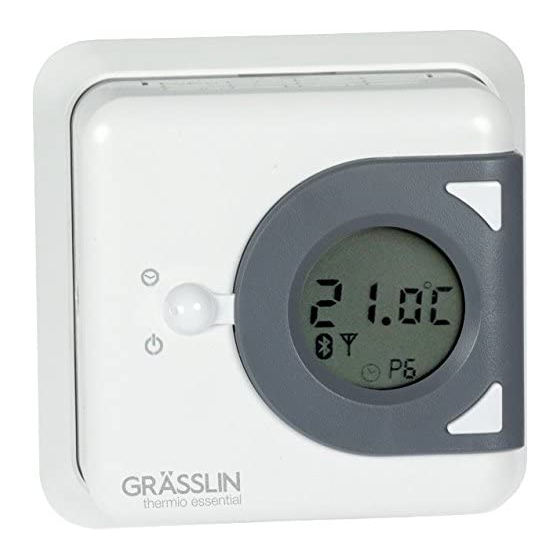
    Vue d'ensemble Structure et fonctionnement Fig. 1: Vue d'ensemble du thermio™ essential smart...
  • Page 72 Mode veille Affichage de l'heure Interrupteur à bascule Symbole de la différence de commutation Symbole de réglage « Set » Touche haut Affichage de la température de consigne et de la température actuelle Symbole de pile Touche bas Périodes par jour Symbole Bluetooth Passe-câble Touche de réinitialisation...
  • Page 73 Description du fonctionnement Le thermostat d'ambiance « thermio™ essential smart » est un thermostat numérique qui sert à réguler la température de systèmes de chauffage dans des locaux fermés. Le thermostat d'ambiance dispose d'une fonction Bluetooth et peut être programmé via un appareil portable. La portée maximale entre l'appareil portable et le thermostat d'ambiance est de 10 mètres (en fonction des locaux).
  • Page 74 Type de régulation Fig. 2: Cavalier Le cavalier (Fig. 2/1) est un pontage reliant électriquement deux broches (contacts). Le cavalier peut être enfiché sur deux positions différentes (position 2 points et position PID) selon la fonction souhaitée. Dans le réglage d'usine, le cavalier est enfiché sur la position PID (Fig. 2/3).
  • Page 75: Sécurité

    Sécurité Utilisation conforme • Le thermostat d'ambiance sert exclusivement à réguler la température (+5 °C bis +35 °C) de sys- tèmes de chauffage dans des locaux fermés. Le respect de toutes les consignes de cette notice est essentiel à une utilisation conforme. Toute utilisa- tion sortant du cadre de l'utilisation conforme ou différente de celle-ci est considérée comme une utili- sation non conforme.
  • Page 76 Risque de blessures en cas de manipulation incorrecte des piles ! En cas de manipulation incorrecte des piles, les piles risquent d'exploser ou un liquide toxique risque de s'écouler des piles. AVERTISSEMENT ! − Ne jamais endommager ou déformer les piles. −...
  • Page 77: Installation

    Installation Lieu de montage Choisir avec soin le lieu de montage pour ne pas fausser les mesures du thermostat d'ambiance. Fig. 3: Exigences relatives au lieu de montage...
  • Page 78: Montage Dans Une Boîte Encastrée

    Montage dans une boîte encastrée Personal: • Électricien Montage de la plaque de montage Monter la plaque de montage avec les vis (3,5 x 25 mm) sur la boîte encastrée (Fig. 6). La flèche (Fig. 6/1) sur la plaque de montage doit pointer vers le haut. Démontage du couvercle du boîtier Desserrer la vis sur le boîtier de l'appareil avec le tournevis cruciforme et démonter le couvercle du boîtier.
  • Page 79 Fig. 4: Schéma de raccordement Interrupteur marche/arrêt COM (contact inverseur, contact conducteur commun) NC (contact rupteur, contact normalement fermé) NO (contact de travail, contact normalement ouvert)
  • Page 80 Insérer et serrer les câbles de raccordement dans la broche correspondante suivant le schéma de raccordement (Fig. 4). Insertion des piles Fig. 5: Insertion des piles Insérer les 2 piles alcalines de type 1,5 V AA LR6 dans le couvercle du boîtier en respectant la polarité...
  • Page 81 Montage du socle du boîtier Fig. 6: Montage du socle du boîtier sur la plaque de montage Montage dans une boîte encastrée sans chevilles avec plaque de montage Montage en saillie sans plaque de montage avec chevilles Monter le socle du boîtier de l'appareil sur la plaque de montage à l'aide des vis (3 x 6 mm) (Fig. 6).
  • Page 82: Montage En Saillie

    Fermeture du boîtier Placer le couvercle du boîtier sur le socle du boîtier et serrer la vis sur le boîtier de l'appareil avec le tournevis cruciforme. Montage en saillie Personal: • Électricien Démontage du couvercle du boîtier Desserrer la vis sur le boîtier de l'appareil avec le tournevis cruciforme et démonter le couvercle du boîtier.
  • Page 83: Insertion Des Piles

    Insérer et serrer les câbles de raccordement dans la broche correspondante suivant le schéma de raccordement (Fig. 4). Montage du socle du boîtier Fixer le socle du boîtier aux chevilles à l'aide des vis (3,5 x 25 mm). Insertion des piles Insérer les 2 piles alcalines de type 1,5 V AA LR6 dans le couvercle du boîtier en respectant la polarité...
  • Page 84: Réglage Du Cycle De Chauffage

    Réglage du cycle de chauffage Sélection du cycle de chauffage Le nombre de mesures de la chaleur peut être réglé sur 3, 6, 9 ou 12 fois par heure (réglage d'usine : 6 fois par heure). Dans le réglage d'usine, le cavalier est enfiché sur la position PID. Cette posi- tion permet de régler le cycle de chauffage.
  • Page 85 • Électricien Réglage du cavalier Desserrer la vis sur le boîtier de l'appareil avec le tournevis cruciforme. Fig. 7: Levage du cavalier Lever le cavalier (Fig. 7/1) dans le couvercle du boîtier avec un tournevis plat. Enficher le cavalier (Fig. 7/1) sur la position PID (Fig. 7/3). Fermeture du boîtier...
  • Page 86 Placer le couvercle du boîtier sur le socle du boîtier et serrer la vis sur le boîtier de l'appareil avec le tournevis cruciforme. Le cavalier est enfiché sur la position PID, cela permet de régler le cycle de chauffage. ð Appuyer sur la touche de réinitialisation (Fig.
  • Page 87: Réglage De L'hystérésis

    Réglage de l'hystérésis Sélection de l'hystérésis Le cavalier peut être enfiché sur deux positions différentes (position 2 points et position PID) selon la fonction souhaitée. Dans le réglage d'usine, le cavalier est enfiché sur la position PID. Cette posi- tion permet de régler le cycle de chauffage. Si le cavalier est enfiché sur la position 2 points, cela permet de régler l'hystérésis.
  • Page 88 • Électricien Réglage du cavalier Desserrer la vis sur le boîtier de l'appareil avec le tournevis cruciforme. Fig. 8: Levage du cavalier Lever le cavalier (Fig. 8/1) dans le couvercle du boîtier avec un tournevis plat. Enficher le cavalier (Fig. 8/1) sur la position 2 points (Fig. 8/2).
  • Page 89 Fermeture du boîtier Placer le couvercle du boîtier sur le socle du boîtier et serrer la vis sur le boîtier de l'appareil avec le tournevis cruciforme. Appuyer sur la touche de réinitialisation (Fig. 1/13) pour réinitialiser l'écran. Réglage de l'hystérésis Maintenir appuyées simultanément la touche haut (Fig.
  • Page 90: Utilisation

    Utilisation Mise en marche du Bluetooth Personal: • Utilisateur Appuyer sur l'interrupteur à bascule (Fig. 1/3) vers le haut et appuyer simultanément sur la touche haut (Fig. 1/6). Le symbole Bluetooth (Fig. 1/11) s'affiche à l'écran. ð...
  • Page 91: Programmation Et Commande Du Thermostat D'ambiance Via Des Appareils Portables

    Programmation et commande du thermostat d'ambiance via des appareils portables Téléchargement de l'app Le thermostat d'ambiance peut être programmé via un appareil portable. Ces fonctions sont programmables via les appareils portables : Réglages de base • Mise en marche/à l'arrêt manuelle •...
  • Page 92 • Écrasement temporaire du programme actuel • Maintien de la température (Hold on) Informations complémentaires L'app pour « thermio essential smart » existe pour les appareils Android et iOS et est disponible dans le store correspondant. Pour les descriptions détaillées de l'émetteur et du récepteur, voir la notice d'utili- sation en ligne correspondante.
  • Page 93: Réglage De La Température De Consigne

    Réglage de la température de consigne Personal: • Utilisateur Appuyer sur l'interrupteur à bascule (Fig. 1/3) vers le haut ou vers le bas pour activer le système de chauffage. L'interrupteur à bascule revient en position initiale. ð Appuyer 2 fois rapidement sur la touche haut (Fig. 1/6) ou la touche bas (Fig. 1/9) pour régler la température de consigne.
  • Page 94: Réglage De L'heure

    L'appareil active le système de chauffage et la température ambiante est régulée selon la ð température de consigne réglée. Le réglage de la température de consigne sur une valeur supéri- eure n'accélère pas le réchauffement du local. La vitesse de réchauffement ne dépend que des conditions dans le système de chauffage.
  • Page 95: Activation Du Verrouillage Des Touches

    Activation du verrouillage des touches Personal: • Utilisateur Appuyer sur l'interrupteur à bascule (Fig. 1/3) vers le bas et appuyer simultanément sur la touche haut (Fig. 1/6) pour activer le verrouillage des touches. Le verrouillage des touches est activé et il n'est plus possible d'effectuer des modifications ð...
  • Page 96 Fonction antigel L'appareil maintient la température ambiante à 5 °C. Le système de chauffage est automatiquement activé lorsque la température ambiante passe en dessous de 5 °C.
  • Page 97: Élimination

    Élimination Élimination non conforme Risque pour l'environnement en cas d'élimination incorrecte ! Risque pour l'environnement en cas d'élimination incorrecte ! − Éliminer les déchets électroniques et les composants électroniques de ENVIRONNEMENT ! manière adéquate, c'est-à-dire selon les groupes de matériaux des composants à...
  • Page 99 Il presente manuale permette un utilizzo sicuro ed efficiente del termostato ambiente "thermio™ essen- tial smart" (di seguito “apparecchio”). Il presente manuale costituisce parte integrante dell’apparecchio e deve essere conservato in modo da risultare accessibile in qualsiasi momento a chiunque utilizzi l’apparecchio.
  • Page 100 © Grässlin GmbH Bundesstr. 36 78112 St. Georgen GERMANIA Download www.graesslin.de : Le seguenti informazioni si trovano su • Dichiarazione di conformità • Istruzioni per il download • Dati tecnici...
  • Page 101 Panoramica..................103 Struttura e funzionamento....................103 Sicurezza.................... 107 Installazione..................109 Montaggio su scatola sotto intonaco................. 110 Montaggio sopra intonaco....................114 Impostazione del ciclo di riscaldamento................116 Impostazione dell’isteresi....................119 Comando.................... 122 Accensione del Bluetooth....................122 Programmazione e comando del termostato ambiente tramite dispositivi mobili....123 Impostazione della temperatura desiderata...............
  • Page 102 Messa in stand-by del termostato ambiente..............127 Smaltimento..................129...
  • Page 103: Panoramica

    Panoramica Struttura e funzionamento Fig. 1: Panoramica thermio™ essential smart...
  • Page 104 Stand-by Visualizzazione dell’ora Tasto basculante Simbolo Differenziale di commutazione Simbolo Set Tasto Su Campo della temperatura desiderata ed effettiva Simbolo Batteria Tasto Giù Periodi al giorno Simbolo Bluetooth Passaggio per cavi Tasto Reset...
  • Page 105 Descrizione del funzionamento Il termostato ambiente "thermio™ essential smart" è un termostato digitale e serve a regolare la tem- peratura di sistemi di riscaldamento in ambienti chiusi. Il termostato ambiente è dotato di una funzione Bluetooth e può essere programmato tramite un dispositivo mobile. La portata massima tra il dispositivo mobile e il termostato ambiente è...
  • Page 106 Tipo di regolazione Fig. 2: Jumper Il jumper (Fig. 2/1) è un ponticello che collega elettricamente due pin (contatti). A seconda della funzione desiderata, il jumper può essere inserito in due posizioni diverse (posizione a 2 punti e PID). Come impo- stazione di fabbrica il jumper si trova in posizione PID (Fig.
  • Page 107: Sicurezza

    Sicurezza Utilizzo conforme alla destinazione d’uso • Il termostato ambiente serve esclusivamente a regolare la temperatura (+5 °C bis +35 °C) di sistemi di riscaldamento in ambienti chiusi. Nell’utilizzo conforme alla destinazione d’uso rientra anche il rispetto di tutte le indicazioni del presente manuale.
  • Page 108 Pericolo di lesioni per gestione scorretta delle batterie! In caso di gestione scorretta delle batterie sussiste il pericolo di esplosione delle batterie o di fuoriuscita dalle stesse di liquidi dannosi per la salute. AVVERTIMENTO! − Non danneggiare né deformare mai le batterie. −...
  • Page 109: Installazione

    Installazione Luogo di installazione Per garantire una misurazione senza errori da parte del termostato ambiente, scegliere un luogo di installazione adatto. Fig. 3: Requisiti per il luogo di installazione...
  • Page 110: Montaggio Su Scatola Sotto Intonaco

    Montaggio su scatola sotto intonaco Personal: • Elettrotecnico Montaggio della piastra di montaggio Montare la piastra di montaggio sulla scatola sotto intonaco con le viti (3,5 x 25 mm) (Fig. 6). La freccia (Fig. 6/1) sulla piastra di montaggio dev’essere rivolta verso l’alto.
  • Page 111 Fig. 4: Schema di allacciamento Interruttore di accensione/spegnimento COM (contatto di commutazione, contatto conduttore comune) NC (contatto di riposo, contatto di apertura) NO (contatto di funzionamento, contatto di chiusura)
  • Page 112 Inserire i cavi di collegamento nel morsetto corrispondente in base allo schema di allacciamento (Fig. 4) e serrarli. Inserimento della batteria Fig. 5: Inserimento delle batterie Inserire le 2 batterie alcaline di tipo 1,5 V AA LR6 nella mascherina dell’alloggiamento con la giusta polarità...
  • Page 113 Montaggio della base dell’alloggiamento Fig. 6: Montaggio della base dell’alloggiamento sulla piastra di montaggio Montaggio su scatola sotto intonaco senza tasselli con piastra di montaggio Montaggio sopra intonaco senza piastra di montaggio con tasselli Montare la base dell’alloggiamento dell’apparecchio sulla piastra di montaggio con le viti (3 x 6 mm) (Fig.
  • Page 114: Montaggio Sopra Intonaco

    Chiusura dell’alloggiamento Posizionare la mascherina dell’alloggiamento sulla base dell’alloggiamento e serrare la vite dell’alloggiamento dell’apparecchio con il giravite a croce. Montaggio sopra intonaco Personal: • Elettrotecnico Smontaggio della mascherina dell’alloggiamento Allentare la vite dell’alloggiamento dell’apparecchio con il giravite a croce e smontare la masche- rina dell’alloggiamento.
  • Page 115 Infilare i cavi di collegamento nell’apparecchio facendoli passare per il passaggio per cavi (Fig. 1/7). Inserire i cavi di collegamento nel morsetto corrispondente in base allo schema di allacciamento (Fig. 4) e serrarli. Montaggio della base dell’alloggiamento Fissare la base dell’alloggiamento ai tasselli da parete con le viti (3,5 x 25 mm). Inserimento della batteria Inserire le 2 batterie alcaline di tipo 1,5 V AA LR6 nella mascherina dell’alloggiamento con la giusta polarità...
  • Page 116: Impostazione Del Ciclo Di Riscaldamento

    Impostazione del ciclo di riscaldamento Selezione del ciclo di riscaldamento Il numero di misurazioni della temperatura può essere impostato su 3, 6, 9 o 12 volte l’ora (impostazione di fabbrica: 6 volte l’ora). Come impostazione di fabbrica il jumper si trova in posizione PID. In questa posizione è...
  • Page 117 • Elettrotecnico Impostazione del jumper Allentare la vite dell’alloggiamento dell’apparecchio con il giravite a croce. Fig. 7: Sollevamento del jumper Sollevare il jumper (Fig. 7/1) nella mascherina dell’alloggiamento con un giravite a taglio. Inserire il jumper (Fig. 7/1) in posizione PID (Fig. 7/3). Chiusura dell’alloggiamento...
  • Page 118 Posizionare la mascherina dell’alloggiamento sulla base dell’alloggiamento e serrare la vite dell’alloggiamento dell’apparecchio con il giravite a croce. Il jumper si trova in posizione PID ed è ora possibile impostare il ciclo di riscaldamento. ð Premere il tasto Reset (Fig. 1/13) per resettare il display. Impostazione del ciclo di riscaldamento Per impostare il ciclo di riscaldamento, tenere premuti contemporaneamente per 5 secondi i tasti Su (Fig.
  • Page 119: Impostazione Dell'isteresi

    Impostazione dell’isteresi Selezione dell’isteresi A seconda della funzione desiderata, il jumper può essere inserito in due posizioni diverse (posizione a 2 punti e PID). Come impostazione di fabbrica il jumper si trova in posizione PID. In questa posizione è possibile impostare il ciclo di riscaldamento. Quando il jumper si trova nella posizione a 2 punti, è...
  • Page 120 Impostazione del jumper Allentare la vite dell’alloggiamento dell’apparecchio con il giravite a croce. Fig. 8: Sollevamento del jumper Sollevare il jumper (Fig. 8/1) nella mascherina dell’alloggiamento con un giravite a taglio. Inserire il jumper (Fig. 8/1) nella posizione a 2 punti (Fig. 8/2). Chiusura dell’alloggiamento Posizionare la mascherina dell’alloggiamento sulla base dell’alloggiamento e serrare la vite dell’alloggiamento dell’apparecchio con il giravite a croce.
  • Page 121 Premere il tasto Reset (Fig. 1/13) per resettare il display. Impostazione dell’isteresi Per impostare l’isteresi tenere premuti contemporaneamente per 5 secondi i tasti Su (Fig. 1/6) e Giù (Fig. 1/9). Il campo del simbolo Differenziale di commutazione (Fig. 1/4) si accende sul display. ð...
  • Page 122: Comando

    Comando Accensione del Bluetooth Personal: • Utente Premere il tasto basculante (Fig. 1/3) verso l’alto e, contemporaneamente, premere il tasto Su (Fig. 1/6). Sul display viene visualizzato il simbolo Bluetooth (Fig. 1/11). ð...
  • Page 123: Programmazione E Comando Del Termostato Ambiente Tramite Dispositivi Mobili

    Programmazione e comando del termostato ambiente tramite dispositivi mobili Download dell’app Il termostato ambiente può essere programmato tramite un dispositivo mobile. Attraverso i dispositivi mobili possono essere programmate queste funzioni: Impostazioni di base • Accensione/spegnimento automatici • Definizione e regolazione dell’offset •...
  • Page 124 • Sovrascrittura temporanea del programma attuale • Mantenimento della temperatura (Hold on) Ulteriori informazioni L’app per “thermio essential smart” è disponibile sia per dispositivi Android che per dispositivi iOS ed è scaricabile dallo store corrispondente. Per una descrizione dettagliata del trasmettitore e del ricevitore vedere il relativo manuale operativo online.
  • Page 125: Impostazione Della Temperatura Desiderata

    Impostazione della temperatura desiderata Personal: • Utente Per attivare il sistema di riscaldamento, premere il tasto basculante (Fig. 1/3) verso l’alto o verso il basso. Il tasto basculante torna nella posizione di partenza. ð Per impostare la temperatura desiderata, premere brevemente per 2 volte consecutive il tasto Su (Fig.
  • Page 126: Impostazione Dell'ora

    L’apparecchio attiva il sistema di riscaldamento e la temperatura ambiente viene regolata ð sulla temperatura desiderata impostata. L’impostazione della temperatura desiderata su un valore supe- riore non accelera il riscaldamento dell’ambiente. La velocità di riscaldamento è determinata esclusivamente dalle condizioni impostate nel sistema di riscaldamento.
  • Page 127: Attivazione Del Blocco Tasti

    Attivazione del blocco tasti Personal: • Utente Per attivare il blocco tasti, premere il tasto basculante (Fig. 1/3) verso il basso e, contemporanea- mente, il tasto Su (Fig. 1/6). Il blocco tasti è attivato e non è più possibile apportare modifiche tramite l’apparecchio. ð...
  • Page 128 Funzione antigelo L’apparecchio mantiene la temperatura ambiente su 5 °C. Il sistema di riscaldamento viene acceso automaticamente quando la temperatura scende al di sotto di 5 °C.
  • Page 129: Smaltimento

    Smaltimento Smaltimento inadeguato Pericolo per l’ambiente per smaltimento scorretto! Uno smaltimento scorretto può provocare pericoli per l’ambiente. − Smaltire correttamente i rottami elettrici e i componenti elettronici, AMBIENTE! ovvero separatamente secondo il gruppo dei materiali delle parti da smaltire. − Non smaltire mai le batterie/gli accumulatori (Direttiva 2006/66/CE) e i rottami elettrici o elettronici con i rifiuti residuali.
  • Page 131 Estas instrucciones permiten manejar de forma segura y eficiente el termostato ambiente «thermio™ essential smart» (en adelante denominado «aparato»). Estas instrucciones son parte integrante del apa- rato y deberán permanecer en todo momento al alcance de cualquier persona que lo maneje. Las personas que manejen el aparato deberán haber leído y comprendido estas instrucciones antes de comenzar cualquier trabajo.
  • Page 132 Los derechos de autor sobre este manual son propiedad del fabricante. © Grässlin GmbH Bundesstr. 36 78112 St. Georgen ALEMANIA Descarga www.graesslin.de puede encontrar la información siguiente: • Declaración de conformidad • Instrucciones de descarga • Datos técnicos...
  • Page 133 Vista general..................135 Estructura y funcionamiento....................135 Seguridad................... 139 Instalación..................141 Montaje sobre roseta empotrada..................142 Montaje de superficie......................146 Definir el ciclo de calentamiento..................148 Regular la histéresis......................151 Manejo....................154 Activar Bluetooth....................... 154 Programar y manejar el termostato ambiente desde dispositivos móviles......155 Regular la temperatura de consigna..................
  • Page 134 Poner el termostato ambiente en modo Stand-by.............. 159 Eliminación..................161...
  • Page 135: Vista General

    Vista general Estructura y funcionamiento Fig. 1: Vista general del thermio™ essential smart...
  • Page 136 Modo Stand-by Ver hora Selector basculante Símbolo Diferencial de activación Símbolo Consigna Botón superior Indicador de temperatura de consigna y real Símbolo Pila Botón inferior Periodos por día Símbolo Bluetooth Pasacables Botón Reset...
  • Page 137 Descripción del funcionamiento El termostato ambiente «thermio™ essential smart» es un termostato digital que sirve para regular la temperatura de sistemas de calefacción en estancias cerradas. El termostato ambiente dispone de fun- ción Bluetooth y puede programarse desde un dispositivo móvil. La distancia máxima entre el disposi- tivo móvil y el termostato ambiente es de 10 metros (dependiendo del inmueble).
  • Page 138 Tipo de regulación Fig. 2: Puente de cortocircuito El puente de cortocircuito (Fig. 2/1) es un puente que une eléctricamente dos pines (contactos). El puente de cortocircuito puede colocarse en dos posiciones distintas (posición de 2 puntos y de PID), dependiendo del funcionamiento que se desee.
  • Page 139: Seguridad

    Seguridad Uso previsto • Este termostato ambiente sirve exclusivamente para regular la temperatura de sistemas de cale- facción en estancias cerradas (+5 °C bis +35 °C). El uso previsto implica también respetar todas las especificaciones de este manual. Cualquier uso que exceda el previsto o difiera de él se considera un uso incorrecto.
  • Page 140 ¡Peligro de lesión si se manipulan incorrectamente las pilas! Si las pilas se manipulan incorrectamente, estas pueden explotar o pueden salir de ellas fluidos nocivos para la salud. ¡ADVERTENCIA! − No dañe ni deforme nunca las pilas. − No cortocircuite nunca los contactos (polo positivo y negativo) de las pilas.
  • Page 141: Instalación

    Instalación Lugar de instalación Para que el termostato ambiente mida correctamente, elija un lugar de instalación adecuado. Fig. 3: Requisitos que debe cumplir el lugar de instalación...
  • Page 142: Montaje Sobre Roseta Empotrada

    Montaje sobre roseta empotrada Personal: • Técnico en electricidad Montar la placa de montaje Monte la placa de montaje sobre la roseta empotrada con los tornillos (3,5 x 25 mm) (Fig. 6). La flecha (Fig. 6/1) situada sobre la placa de montaje tiene que apuntar hacia arriba.
  • Page 143 Fig. 4: Esquema de conexión Contacto de conexión y desconexión COM (contacto inversor, contacto conductor común) NC (contacto de reposo, contacto de apertura) NO (contacto de trabajo, contacto de cierre)
  • Page 144 Por medio del esquema de conexión (Fig. 4), introduzca los cables de conexión en los bornes correspondientes y fíjelos. Colocar la pila Fig. 5: Colocar la pila Coloque 2 pilas alcalinas de 1,5 V AA LR6 con la polaridad correcta (Fig. 5) en la tapa de la carcasa.
  • Page 145 Montar el fondo de la carcasa Fig. 6: Montar el fondo de la carcasa sobre la placa de montaje Montaje sobre roseta empotrada Sin tacos y con placa de montaje Montaje en superficie Sin placa de montaje y con tacos Monte el fondo de la carcasa del aparato sobre la placa de montaje con los tornillos (3 x 6 mm) (Fig.
  • Page 146: Montaje De Superficie

    Cerrar la carcasa Coloque la tapa de la carcasa sobre el fondo de la carcasa y apriete el tornillo de la carcasa del aparato con el destornillador en cruz. Montaje de superficie Personal: • Técnico en electricidad Desmontar la tapa de la carcasa Suelte el tornillo de la carcasa del aparato con el destornillador en cruz y desmonte la tapa de la carcasa.
  • Page 147 Por medio del esquema de conexión (Fig. 4), introduzca los cables de conexión en los bornes correspondientes y fíjelos. Montar el fondo de la carcasa Fije el fondo de la carcasa a los tacos de la pared con los tornillos (3,5 x 25 mm). Colocar la pila Coloque 2 pilas alcalinas de 1,5 V AA LR6 con la polaridad correcta (Fig.
  • Page 148: Definir El Ciclo De Calentamiento

    Definir el ciclo de calentamiento Seleccionar el ciclo de calentamiento El número de mediciones de calor puede establecerse en 3, 6, 9 o 12 veces por hora (ajuste de fábrica: 6 veces por hora). El puente de cortocircuito está colocado de fábrica en la posición de PID. En esta posición puede definirse el ciclo de calentamiento.
  • Page 149 • Técnico en electricidad Ajustar el puente de cortocircuito Suelte el tornillo de la carcasa del aparato con el destornillador en cruz. Fig. 7: Levantar el puente de cortocircuito Levante el puente de cortocircuito (Fig. 7/1) de la tapa de la carcasa con un destornillador plano. Coloque el puente de cortocircuito (Fig.
  • Page 150 Coloque la tapa de la carcasa sobre el fondo de la carcasa y apriete el tornillo de la carcasa del aparato con el destornillador en cruz. El puente de cortocircuito está en la posición de PID; ahora puede definirse el ciclo de calen- ð...
  • Page 151: Regular La Histéresis

    Regular la histéresis Seleccionar la histéresis El puente de cortocircuito puede colocarse en dos posiciones distintas (posi- ción de 2 puntos y posición de PID), dependiendo del funcionamiento que se desee. El puente de cortocircuito está colocado de fábrica en la posición de PID. En esta posición puede definirse el ciclo de calentamiento.
  • Page 152 • Técnico en electricidad Ajustar el puente de cortocircuito Suelte el tornillo de la carcasa del aparato con el destornillador en cruz. Fig. 8: Levantar el puente de cortocircuito Levante el puente de cortocircuito (Fig. 8/1) de la tapa de la carcasa con un destornillador plano. Coloque el puente de cortocircuito (Fig.
  • Page 153 Cerrar la carcasa Coloque la tapa de la carcasa sobre el fondo de la carcasa y apriete el tornillo de la carcasa del aparato con el destornillador en cruz. Pulse el botón Reset (Fig. 1/13) para restablecer el display. Fijar la histéresis Para fijar la histéresis mantenga pulsados a la vez los botones superior (Fig.
  • Page 154: Manejo

    Manejo Activar Bluetooth Personal: • Usuario Empuje el selector basculante (Fig. 1/3) hacia arriba y pulse a la vez el botón superior (Fig. 1/6). ð El símbolo Bluetooth (Fig. 1/11) aparece en el display.
  • Page 155: Programar Y Manejar El Termostato Ambiente Desde Dispositivos Móviles

    Programar y manejar el termostato ambiente desde dispositivos móviles Descargar la app El termostato ambiente puede programarse desde un dispositivo móvil. Desde el dispositivo móvil pueden programarse las funciones siguientes: Configuración básica • Encender y apagar manualmente • Definir y modificar la desviación •...
  • Page 156 • Mantener la temperatura (Hold on) Información más detallada La app del "thermio essential smart" está disponible tanto para dispositivos con Android como para dis- positivos con iOS en la tienda online correspondiente. Encontrará una descripción detallada del emisor y el receptor en las instrucciones de manejo online correspondientes.
  • Page 157: Regular La Temperatura De Consigna

    Regular la temperatura de consigna Personal: • Usuario Empuje hacia arriba o hacia abajo el selector basculante (Fig. 1/3) para controlar el sistema de calefacción. El selector basculante vuelve a su posición inicial. ð Para fijar la temperatura de consigna pulse brevemente 2 veces seguidas el botón superior (Fig.
  • Page 158: Fijar La Hora

    El aparato controla el sistema de calefacción y este regula la temperatura ambiente hasta ð que alcanza la de consigna. Fijar un valor más alto para la temperatura de consigna no calienta la estancia más rápido. La velocidad de calentamiento depende únicamente de las condiciones del sistema de calefac- ción.
  • Page 159: Activar El Bloqueo De Teclas

    Activar el bloqueo de teclas Personal: • Usuario Para activar el bloqueo de teclas, empuje el selector basculante (Fig. 1/3) hacia abajo y pulse a la vez el botón superior (Fig. 1/6). El bloqueo de teclas está activado y no pueden realizarse cambios en el aparato. ð...
  • Page 160 Función anticongelación El aparato mantiene la temperatura ambiente a 5 °C. El sistema de calefacción se enciende automáticamente cuando la tempera- tura ambiente baja por debajo de 5 °C.
  • Page 161 Eliminación Eliminación incorrecta ¡Peligro para el medio ambiente en caso de eliminación incorrecta! Una eliminación incorrecta puede generar peligros para el medio ambiente. − Elimine correctamente los componentes y desechos electrónicos, es ¡MEDIO AMBIENTE! decir, separados por grupos de materiales de los componentes dese- chados.
  • Page 164 Grässlin GmbH Bundesstrasse 36 78112 St. Georgen GERMANY Telephone: +49 7724 933-0 Fax: +49 7724 933-240 info@graesslin.de www.graesslin.de 80.10.1475.7/0217/V01...

Table des Matières