Publicité

Les langues disponibles
  • FR

Les langues disponibles

Liens rapides

DMX CONTROLLED RELAY SWITCH
DMX controlled relay switch
DMX-gestuurde relais
Relais à pilotage DMX
DMX-gesteurter relais
Relé controlado por DMX
VM138
4
11
18
25
32

Publicité

Table des Matières
loading

Sommaire des Matières pour Velleman VM138

  • Page 1 DMX CONTROLLED RELAY SWITCH VM138 DMX controlled relay switch DMX-gestuurde relais Relais à pilotage DMX DMX-gesteurter relais Relé controlado por DMX...
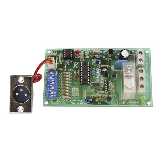
  • Page 2 DMX mode DMX address selection DMX input power supply connector Relay output (NC - COM - NO) Mode DMX DMX adres selectie DMX ingang Voedingaansluiting Relais uitgang (NC - COM - NO) DMX mode Paramétrage du canal DMX L'entrée DMX Connexion d'alimentation Sortie relais (NC - COM - NO) DMX-Modus...
  • Page 3 Max. 8A @ 230V Remark: Some DMX controllers have a reversed DMX polarity. Swap DATA+ and DATA- Opmerking: Bij sommige DMX controllers is de DMX polariteit omgekeerd, dan dient DATA+ en DATA- verwisseld te worden Remarque : Certains contrôleurs DMX ont une polarité DMX inversée. Le cas échéant, inversez DATA+ et DATA- Bemerkung: Bei manchen DMX-Controllern ist die DMX-Polarität umgekehrt.
  • Page 4 This product is guaranteed against defects in components and construction from the moment it is purchased and for a period of TWO YEAR starting from the date of sale. This guarantee is only valid if the unit is submitted together with the original purchase invoice. VELLEMAN components Ltd limits its responsibility to the reparation of defects or, as VELLEMAN components Ltd deems necessary, to the replacement or reparation of defective components.
  • Page 5 Specifications & features SPECIFICATIONS & FEATURES This module allows you to control a relay by means of the well-known DMX512 protocol. This is used to control dimmers, scanners, moving-head spots and other lighting devices with a simple wiring. In some cases, a simple ON/OFF selection is desired. there is where this module comes in. It is actually a bus-controlled power driver.
  • Page 6 Channel 9 : dip / on : #1 + #4 (=1+8=9) Channel 69 : dip / on : #1 + #3 + #7 (=1+4+64=69) Please go to our website (www.velleman.be) and consult the handy graphical help program showing the position of the switches. Setting up will become easy!
  • Page 7 DMX channel Terminator: The DMX protocol implies that the last device in a series must be fitted with a 120 ohms terminator. The module has already been fitted with the terminator. Activate it as follows: position DIP switch nr 10 to ON.
  • Page 8 DMX channel LED LD2 “Error” Functions: LD2, the “Error” LED has following functions: Flashes once at turn-ON of the module. Allows you to check if the CPU is functioning. Flashes slowly when there is no DMX signal reception, no connection between the DMX controller and the module, a DMX signal error or no signal compatibility.
  • Page 9 DMX channel Manual Override Function: Exceptionally, the relay must be activated, even when there is no DMX signal (e.g. when testing a light bulb). Proceed as follows: Position the DMX address to 0 Mount jumper JP1 Switch on the 12V power; the relay will activate regardless of the DMX value.
  • Page 10: Safety Instructions

    Facilitate the operation of the device by familiarising yourself with its adjustments and indications. Velleman modules are not suitable for use or as part of life support systems, or systems that might create hazardous situations of kind. Repair under warranty is only possible with date and proof of purchase.
  • Page 11 JAAR vanaf de aankoop. De waarborg geldt enkel indien het produkt voorgelegd wordt samen met het origineel aankoop bewijs. De verplichtingen van VELLEMAN COMPONENTS N.V. beperken zich tot het herstellen van defecten of, naar vrije keuze van VELLEMAN COMPONENTS N.V., tot het vervangen of herstellen van defecte onderdelen.
  • Page 12: Eigenschappen & Technische Gegevens

    Eigenschappen en technische gegevens EIGENSCHAPPEN & TECHNISCHE GEGEVENS Deze module laat u toe een relais te bedienen door middel van het alom bekende DMX512-protocol. Dit protocol werd in 1986 door USITT ontwikkeld met als doel dimmers, scanners, moving heads en andere verlichting met eenvoudige bedrading te besturen.
  • Page 13 DMX kanaal INSTELLEN VAN HET DMX KANAAL Het DMX kanaal of “DMX adres" wordt ingesteld door middel van de DIPSWITCH, SW1. Het ingestelde DMX kanaal is instelbaar tussen 1 en 511, kanaal 0 wordt niet gebruikt. De schakelaartjes 1 tot 9 vormen een binair getal die het DMX kanaal weergeeft.
  • Page 14 : dip / on : #1 + #3 + #7 (=1+4+64=69) Op onze website, www.velleman.be, bij de rubriek “downloads" vindt U een handig hulpprogramma dat je op een grafische manier de stand van de schakelaars weergeeft en zo het instellen tot een kinderspel herleid !
  • Page 15 DMX kanaal 1. Zet schakelaar 10 van SW1 op ON als U deze module als enig aangesloten DMX toestel gebruikt of dit de laatst aangeslotene is in de rij. (zie “terminator”). 2. Sluit een 12V (on)gestabiliseerde spanning aan op de ingang “12V DC”, (SK1) en schakel deze daarna in. 3.
  • Page 16 DMX kanaal JP2: Relay HOLD status : Indien gemonteerd : relais valt zeker af indien de DMX verbinding wordt verbroken. Niet gemonteerd : relais behoud zijn status indien de DMX verbinding wordt verbroken. “Manual Override”- functie : Het kan uitzonderlijk nodig zijn het relais te laten aantrekken zonder dat de schakeling is aangestuurd door een DMX signaal (vb.
  • Page 17: Veiligheidsaanwijzingen

    Zorgt ervoor dat u met alle bedieningselementen vertrouwd raakt, wanneer U met het toestel zal werken. Velleman modules zijn niet geschikt voor gebruik in of als gedeelte van systemen welke levensfuncties in stand houden of systemen welke gevaarlijke situaties van gelijk welke aard kunnen veroorzaken.
  • Page 18 Cette garantie est uniquement valable si le produit est accompagné de la preuve d’achat originale. Les obligations de VELLEMAN COMPONENTS S.A. . se limitent à la réparation des défauts ou, sur seule décision de VELLEMAN COMPONENTS S.A. au remplacement ou à la réparation des pièces défectueuses.
  • Page 19: Caracteristiques Et Donnees Techniques

    Caractéristiques et données techniques CARACTERISTIQUES ET DONNEES TECHNIQUES Ce module vous permet de contrôler un relais à l'aide du célèbre protocole DMX512. Ce protocole a été développé par USITT en 1986 afin de contrôler des variateurs, des scanners, des projecteurs lyre ou tout autre appareil d'éclairage muni d'un simple câblage.
  • Page 20: Paramétrage Du Canal Dmx

    Canal DMX PARAMÉTRAGE DU CANAL DMX Le canal DMX ou "adresse DMX" est paramétré à l’aide de l’interrupteur DIP SW1. Le canal peut être configuré de 1 à 511 ; le canal 0 n’est pas utilisé. Les interrupteurs 1 à 9 constituent un chiffre binaire représentant le canal DMX.
  • Page 21 : dip / on : #1 + #3 + #7 (=1+4+64=69) Visitez notre site web www.velleman.be, rubrique “Téléchargements”. Vous y trouverez un logiciel de support qui vous indiquera de manière graphique la position des interrupteurs, ce qui facilitera considérablement le paramétrage.
  • Page 22 Canal DMX 1. Positionnez interrupteur DIP n° 10 sur ON si vous désirez utiliser le module de manière autonome ou s’il est le dernier appareil dans une série (voir "terminaison"). 2. Connectez une tension 12V (non) régulée à l’entrée "12VDC" (SK1) en dernier. Branchez le module. 3.
  • Page 23 Canal DMX JP2 : Relais HOLD : Monté : le relais se désactive lorsque la connexion DMX est interrompue. Non monté : le relais retient son état lorsque la connexion DMX est interrompue. La fonction d’annulation : Exceptionnellement, il faudra activer le relais sans que la commutation ait été commandée par un signal DMX (p.ex.
  • Page 24: Consignes De Sécurité

    Familiarisez-vous avec tous les réglages et indications de l'appareil afin de faciliter l'opération. Les modules Velleman ne conviennent pas pour une utilisation dans ou comme parties de systèmes servant à assurer des fonctions de survie ou des systèmes pouvant entraîner des situations dangereuses, de quelque nature qu‘elles soient.
  • Page 25 Die Garantie kann nur beansprucht werden, wenn das Produtk mit der Originalrechnung abgegeben wird. Die Verpflichtungen der VELLEMAN COMPONENTS AG beschränken sich auf die Aufhebung der Fehler, oder, nach freier Wahl der VELLEMAN COMPONENTS AG , auf den Austausch oder die Reparation der fehlerhaften Teile.
  • Page 26: Technische Eigenschaften

    Spezifikationen und Technische kenndaten SPEZIFIKATIONEN & TECHNISCHE DATEN Mit diesem Bausatz können Sie ein Relais über das weit und breit bekannte DMX512- Protokoll bedienen. Das Protokoll ist 1986 von USITT entwickelt worden und hat die Absicht, Dimmers, Scanners, Moving Heads und andere Beleuchtung mit einfacher Verdrahtung zu steuern.
  • Page 27 DMX-Kanals EINSTELLEN DES DMX-KANALS Der DMX-Kanal oder die “DMX-Adresse” wird mit DIP-Schalter SW1 eingeschaltet. Der eingestellte DMX- Kanal ist zwischen 1 und 511 einstellbar. Kanal 0 wird nicht verwendet. Die Schalter 1 bis 9 bilden eine binäre Zahl, die den DMX-Kanal anzeigt. Schalter 1 ist LSB, und 9 ist MSB. Ändern Sie den DMX-Kanal also nur wenn der module deaktiviert ist.
  • Page 28 Kanal 69 : dip / on : #1 + #3 + #7 (=1+4+64=69) Besuchen Sie unsere Website, www.velleman.be, unter “Downloads” finden Sie ein geschicktes Hilfsprogramm, das auf grafischer Weise die Position der Schalter anzeigt und das Einstellen so vereinfacht! Abschlusswiderstand: Das DMX-Protokoll bedeutet, dass das letzte Gerät der Reihe mit einem Abschlusswiderstand von 120 ohm...
  • Page 29 DMX-Kanals 1. Stellen Sie Schalter 10 von SW1 auf ON wenn Sie den module als einziges angeschlossenes DMX-Gerät verwenden oder wenn der module das letzte angeschlossene Gerät der Reihe ist. (siehe “Abschlusswiderstand”) 2. Schließen Sie eine 12V- (nicht) stabilisierte Spannung an den Eingang “12V DC”, (SK1) an und schalten Sie danach module ein.
  • Page 30 DMX-Kanals JP2: Relay-HOLD-Status : Wenn montiert : Relais wird deaktiviert wenn die DMX-Verbindung verbrochen wird. Nicht montiert : Relais behält seinen Status wenn die DMX-Verbindung verbrochen wird. “Manual Override”- Funktion: Ausnahmsweise muss das Relais aktiviert werden ohne dass es ein DMX-Signal gibt (z.B. Lampen überprüfen).
  • Page 31: Sicherheitshinweise

    Sicherheits– und Warnhinweise WARNUNG Lassen Sie Reparaturen durch Fachleute erfolgen Installieren Sie das Modul nicht in einer Umgebung mit stehendem oder fließendem Wasser oder in einer sehr feuchten Umgebung SICHERHEITSHINWEISE Gehen Sie behutsam mit dem Modul um. Es fallen lassen, kann die Leiterplatte und das Gehäuse beschädigen. Überschreiten Sie nie die in den technischen Daten erwähnten Eingangsgrößen.
  • Page 32 Este producto está garantizado contra defectos de componentes y construcción a partir de su adquisición y durante un período de TRES AÑO a partir de la fecha de venta. Esta garantía sólo es válida si la unidad se entrega junto con la factura de compra original. VELLEMAN COMPONENTS Ltd. limita su responsabilidad a la reparación de los defectos o, si VELLEMAN COMPONENTS Ltd.
  • Page 33: Características Técnicas

    Especificaciones y Características ESPECIFICARTIONES Y CARACTERÍSTICAS Este module le permite controlar un relé con el famoso protocolo DMX512. Este protocolo ha sido desarrollado por USITT en 1986 para controlar dimmers, escáneres, cabezas móviles o cualquier otro aparato de iluminación equipado con un sencillo cableado.
  • Page 34 El canal DMX AJUSTAR EL CANAL DMX El canal DMX o "dirección DMX" se ajusta con el interruptor DIP SW1. Es posible configurar el canal de 1 a 511; el canal 0 no se utiliza. Los interruptores de 1 a 9 constan de una cifra binaria que representa el canal DMX.
  • Page 35 Canal 69 : dip / on : #1 + #3 + #7 (=1+4+64=69) Visite nuestra página web www.velleman.be, sección "Descargas". Encontrará un programa de ayuda que le indicará de manera gráfica la posición de los interruptores, lo que facilitará la programación.
  • Page 36 El canal DMX 1. Ponga el interruptor DIP n° 10 en la posición ON si quiere utilizar el módulo de manera autónoma o si es el último aparato de una serie (véase "terminación"). 2. Conecte por último una tensión de 12V (no) estabilizada a la entrada "12VDC" (SK1). Conecte el módulo. 3.
  • Page 37 El canal DMX JP2: Relé HOLD: Montado : el relé se desactiva si la conexión DMX se interrumpe. No montado : el relé mantiene su estado si la conexión DMX se interrumpe. La función "manual override" : Excepcionalmente, es necesario activar el relé sin que haya una señal DMX (p.ej. para comprobar bombillas).
  • Page 38: Las Medidas De Seguridad

    Siga cuidadosamente todas las instrucciones y familiarícese con los ajustes al operar este dispositivo. Los modulo Velleman no son adecuados para una utilización dentro o corno sistema destinado a garantizar funciones para sobrevivir o sistemas conllevando situaciones peligrosas sea cual su naturaleza.
  • Page 40 +31(0)76 514 7563 Velleman Inc. +1(817)284-7785 Spain Velleman Components +32(0)9 384 36 11 Modifications and typographical errors reserved - © Velleman Components nv - HVM138G - 2008 - ED1 5 4 1 0 3 2 9 3 9 8 3 6 1...

Table des Matières