
Manuels Connexes pour IFM Electronic efector500 PY995 Serie


Sommaire des Matières pour IFM Electronic efector500 PY995 Serie
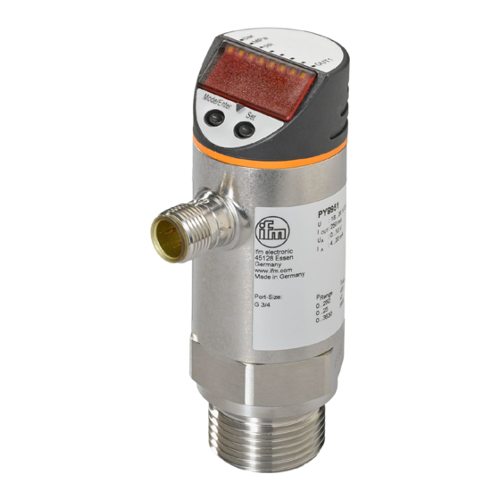
- Page 1 Bedienungsanleitung Operating instructions Notice utilisateurs Elektronischer Drucksensor Electronic pressure sensor Capteur de pression électronique PY995x...
-
Page 2: Table Des Matières
Inhalt Sicherheitshinweise ....... . Seite 5 Bedien- und Anzeigeelemente ......Seite 5 Bestimmungsgemäße Verwendung . - Page 3 Menü-Übersicht / Menu structure / Structure du menu *nur / only / seul PY9954 Mode/Enter...
- Page 4 Programmieren / Programming / Programmation Mode/Enter Set Parameter aufrufen Select parameters Sélectionner les paramètres Mode/Enter Set Werte einstellen* Set Values* Mode/Enter Set Régler la valeurs* > 5 s Werte bestätigen Acknowledgement of values Mode/Enter Set Confirmer la valeur *Wert verringern: Lassen Sie die Anzeige bis zum maximalen Einstellwert laufen.
-
Page 5: Sicherheitshinweise
Sicherheitshinweise Lesen Sie vor der Inbetriebnahme des Gerätes die Produktbeschreibung. Vergewissern Sie sich, dass sich das Produkt uneingeschränkt für die betreffende Applikationen eignet. Die Missachtung von Anwendungshinweisen oder technischen Angaben kann zu Sach- und/oder Personenschäden führen. Prüfen Sie in allen Applikationen die Verträglichkeit der Produktwerkstoffe (s. -
Page 6: Bestimmungsgemäße Verwendung
Bestimmungsgemäße Verwendung • Der Drucksensor erfasst den Systemdruck, • zeigt ihn durch ein Display an • und erzeugt 2 Ausgangssignale entsprechend der eingestellten Ausgangskonfiguration. Ausgang 1 Ausgang 2 Hysteresefunktion / Schließer (Hno) Analog 4 ... 20 mA (I) Hysteresefunktion / Öffner (Hnc) Fensterfunktion / Schließer (Fno) Analog 0 ... -
Page 7: Betriebsarten
Betriebsarten Run-Modus Normaler Arbeitsbetrieb Nach dem Einschalten der Versorgungsspannung befindet sich das Gerät im Run-Modus. Es führt seine Überwachungsfunktion aus und schaltet die Ausgänge entsprechend der eingestellten Parameter. Das Display zeigt den aktuellen Systemdruck an, die gelbe LED signa- lisiert den Schaltzustand des Ausgangs. Display-Modus Anzeige der Parameter und der eingestellten Parameterwerte Das Gerät geht durch kurzen Druck auf die Taste “Mode/Enter”... -
Page 8: Montage
Montage Stellen Sie vor Ein- und Ausbau des Sensors sicher, dass die Anlage druckfrei ist. Befestigen Sie den Drucksensor an einem G¾-Prozeßanschluß (s. Typaufkleber “Port Size”). Elektrischer Anschluss Das Gerät darf nur von einer Elektrofachkraft installiert werden. Befolgen Sie die nationalen und internationalen Vorschriften zur Errichtung elektrotechnischer Anlagen. -
Page 9: Programmieren
Programmieren Drücken Sie die Taste Mode/Enter, bis der gewünschte Parameter Mode/Enter Set im Display erscheint. Drücken Sie die Taste Set und halten Sie sie gedrückt. Mode/Enter Set Der aktuelle Parameterwert wird 5 s lang blinkend angezeigt, danach wird er erhöht* (schrittweise durch Einzeldruck oder kontinuierlich durch Festhalten der Taste). -
Page 10: Inbetriebnahme / Betrieb
Inbetriebnahme / Betrieb elektrischem Anschluss und Programmie-rung, ob das Gerät sicher funktioniert. Störanzeigen während des Betriebs: Überlastdruck (Messbereich überschritten) Unterlastdruck (Messbereich unterschritten) Blinkend: Kurzschluss im Schaltausgang* *Der Ausgang ist abgeschaltet, solange der Kurzschluss andauert. Diese Meldungen werden auch bei ausgeschaltetem Display angezeigt. Technik-Information / Funktionsweise / Parameter Einstellbare Parameter Schaltpunkt... - Page 11 Konfiguration für den Analogausgang Es sind 2 Funktionen einstellbar: I = 4 ... 20 mA / U = 0 ... 10 V. Erweiterte Funktionen Dieser Menüpunkt enthält ein Untermenü mit weiteren Parametern. Durch kurzen Druck auf die Set-Taste wird das Untermenü...
- Page 12 Verzögerungszeit für den Schaltausgang dS1 = Einschaltverzögerung; dr1 = Ausschaltverzögerung. Der Ausgang ändert seinen Schaltzustand nicht sofort bei Eintritt des Schaltereignisses, sondern erst nach Ablauf der Verzögerungszeit. Besteht das Schaltereignis nach Ablauf der Verzögerungszeit nicht mehr, ändert sich der Schaltzustand des Ausgangs nicht.
- Page 13 Hysteresefunktion: Hysterese hält Schaltzustand des Ausgangs sta- bil, wenn der Systemdruck um den Sollwert schwankt. Hysterese Bei steigendem Systemdruck schaltet Ausgang Erreichen des Schaltpunkts (SP1); fällt der Systemdruck wieder ab, schaltet der Ausgang erst dann zurück, wenn der Rückschalt- punkt (rP1) erreicht ist. Die Hysterese ist einstellbar: Zuerst wird der Schaltpunkt festgelegt, dann im gewünschten Abstand der Rückschaltpunkt.
-
Page 14: Technische Daten
Technische Daten Betriebsspannung [V] ......18 ... 36 DC Stromaufnahme [mA] ........< 50 Strombelastbarkeit [mA] . -
Page 16: Safety Instructions
Safety instructions Read the product description before installing the unit. Ensure that the product is suitable for your application without any restrictions. Non-adherence to the operating instructions or technical data can lead to personal injury and/or damage to property. In all applications check compliance of the product materials (see Technical data) with the media to be measured. -
Page 17: Function And Features
Function and features • The pressure sensor detects the system pressure, • shows the current system pressure on its display, • and generates 2 output signals according to the set output configuration. Output 1 Output 2 hysteresis function / N.O. (Hno) analogue 4 ... -
Page 18: Operating Modes
Operating modes Run mode Normal operating mode At power on the unit is in the Run mode. It carries out its measure- ment and evaluation functions and provides output signals according to the set parameters. The display shows the current system pressure. The yellow LED indi- cates the switching state of the output. -
Page 19: Installation
Installation Before mounting and removing the sensor, make sure that no pressure is applied to the system. Mount the pressure sensor on a G¾ process connection. Electrical connection The unit must be connected by a suitably qualified electrician. The national and international regulations for the installation of electrical equipment must be observed. -
Page 20: Programming
Programming Press the Mode/Enter button several times until the respective Mode/Enter Set parameter is displayed. Press the Set button and keep it pressed. The current parameter Mode/Enter Set value flashes for 5 s, then the value is increased* (incremental by pressing briefly or scrolling by holding pressed). -
Page 21: Installation And Set-Up / Operation
Installation and set-up / operation After mounting, wiring and setting check whether the unit operates correctly. Fault indication Overload (above measuring range of the sensor). Underload (below measuring range of the sensor). Flashing: short circuit in the switching output 1*. *The output concerned is switched off as long as the short circuit continues. - Page 22 - Press the "Set" button and hold it pressed until the valid code no. is shown. - Then briefly press the "Mode/Enter" button. Delivery by ifm electronic: no access restriction. Display unit The measured value and the values for SP1, rP1 can be displayed in the following units: •...
- Page 23 Delay time for the switching output dS1 = switch-on delay; dr1 = switch-off delay. The output does not immediately change its switching status when the switching condition is met but when the delay time has elapsed. If the switching condition is no longer met when the delay time has elapsed, the switching state of the output does not change.
-
Page 24: Window Function
Hysteresis function: The hysteresis keeps the switch- ing state of the output stable if the system pressure varies about the preset value. With the system hysteresis pressure rising, output switches when the switch-on point has been reached (SP1). With the system pressure falling the output does not switch back until the switch-off point (rP1) has been reached. -
Page 25: Technical Data
Technical data Operating voltage [V] ......18 ... 36 DC Current consumption [mA] ....... . . < 50 Current rating [mA] . -
Page 26: Remarque Sur La Sécurité
Remarque sur la sécurité Avant la mise en service de l'appareil, veuillez lire la descrip- tion du produit. Assurez-vous que le produit est approprié pour l'application concernée sans aucune restriction. Le non-respect des remarques ou des données techniques peut provoquer des dommages matériels et/ou corporels. Pour toutes les applications, veuillez vérifier la compatibilité... -
Page 27: Fonctionnement Et Caractéristiques
Fonctionnement et caractéristiques • Le capteur de pression détecte la pression du circuit • visualise la pression actuelle à l’aide d’un affichage digital • et génère 2 signaux de sortie selon la configuration de sortie réglée. Sortie 1 Sortie 2 hystérésis / N. -
Page 28: Modes De Fonctionnement
Modes de fonctionnement Mode Run Mode de fonctionnement normal Après la mise sous tension l'appareil se trouve en mode Run. Il surveille et génère les signaux de sortie selon les paramètres réglés. L'affichage digital indique la pression actuelle du circuit. La LED jaune indique l'état de commutation de la sortie. -
Page 29: Montage
Montage Avant de monter / démonter le capteur, s'assurer que la pression n'est pas appliquée au circuit. Monter le capteur de pression à l’aide d’un montage process G¾. Raccordement électrique L'appareil doit être monté par un électricien. Les règlements nationaux et internationaux relatifs à l'installation de matériel électrique doivent être respectés. -
Page 30: Programmation
Programmation Appuyer sur le bouton Mode/Enter plusieurs fois jusqu'à ce que le Mode/Enter Set paramètre désiré soit affiché. Appuyer sur le bouton Set et le maintenir appuyé. La valeur de paramètre actuelle cli- Mode/Enter Set gnote pendant 5 s, après la valeur est incrémentée* (pas à... -
Page 31: Mise En Service / Fonctionnement
Mise en service / Fonctionnement Après le montage, le câblage et et la programmation, vérifier le bon fonctionnement de l'appareil. Indication de défauts Surpression (au-dessus de l'étendue de mesure du capteur). Souspression (au-dessous de l'étendue de mesure du capteur). Clignotant: court-circuit de la sortie de commutation 1*. *La sortie respective est désactivée tant que le court-circuit continue. - Page 32 - Appuyer sur le bouton Set et le maintenir appuyé jusqu'à ce que le n° du code valable soit indiqué. - Ensuite appuyer brièvement sur le bouton "Mode/Enter". Livraison par ifm electronic : sans restriction d'accès. Unité d'affichage La valeur mesurée et les valeurs pour SP1, rP1 peuvent être affichées dans les unités suivantes:...
- Page 33 Temporisation pour la sortie de commutation dS1 = temporisation à l’enclenchement; dr1 = temporisation au déclenchement La sortie ne change pas son état de commutation immédiate- ment. La commutation se produit après l'écoulement de la tem- porisation. Si l'évènement de commutation n'existe plus après l'écoulement de la temporisation, la sortie ne change pas d'état.
-
Page 34: Fonction Fenêtre
Fonction hystérésis: L'hystérésis garantit un état de commutation stable de la sortie en cas de fluctuations de la pres- sion du circuit autour de la valeur hystérésis présélectionnée. Si la pression du circuit augmente, la sortie com- mute lorsque la consigne haute est atteinte (SP1);... -
Page 35: Données Techniques
Données techniques Tension d'alimentation [V] ......18 ... 36 DC Consommation [mA] ........< 50 Courant de sortie [mA] . -
Page 36: Dimensions
Maßzeichnung Scale drawing Dimensions 1 Display 2 LEDs 3 Programmiertaste 1 display 2 LED’s 3 programming button 1 visualisation 2 LEDs 3 bouton poussoir... - Page 37 Einstellbereiche / Setting ranges / Plages de réglage ΔP Uni = bAr PY9951 PY9954 -0,90 10,00 -0,95 9,95 0,05 ΔP Uni = PSI PY9951 3 620 3 600 PY9954 +145 +144 ΔP Uni = MPa PY9951 25,0 24,9 PY9954 -0,090 +1,000 -0,095 +0,995...
-
Page 38: Eingestellte Parameter-Werte Set Parameter Values Valeurs De Paramètre Réglées
Eingestellte Parameter-Werte Set parameter values Valeurs de paramètre réglées...