Beta 1550/1 Mode D'emploi

Sommaire des Matières pour Beta 1550/1
- Page 1 1550/1 ISTRUZIONI PER L’USO INSTRUCTIONS MODE D’EMPLOI GEBRUIKSAANWIJZING GEBRAUCHSANWEISUNG BETA UTENSILI spa Via Volta, 18 INSTRUCCIONES 20050 SOVICO (MI) ITALY Tel. 039-2077.1 Fax 039-2010742 INSTRUKCJA OBSLUGI...
-
Page 2: Table Des Matières
INSTRUKCJA OBSLUGI 1550/1 SEZIONE 0 ROZDZIAL 6 INDICE Pagine PRZELADUNEK, TRANSPORT I OPAKOWANIEE SEZIONE 1 INTRODUZIONE Czynnosci te musza byc wykonywane przez pracowników odpowiedzialnych za 1.1 INTRODUZIONE AL MANUALE transport i prace przeladunkowe, uzywajacych stosownych srodków ochrony osobistej 1.2 GARANZIA (rekawice i okulary ochronne, buty ochronne). -
Page 3: Instrukcja Obslugi
– Zwolnic sprezyne do pozycji odprezonej; la vita dello stesso. Il compressore non presenta pericolo per l’operatore se usato – teraz podniesc oslone. secondo le istruzioni fornite dalla BETA UTENSILI. Montaz amortyzatora przeprowadza sie w nastepujacy sposób: – wlozyc nowy amortyzator w sprezyne;... -
Page 4: Identificazione Del Compressore
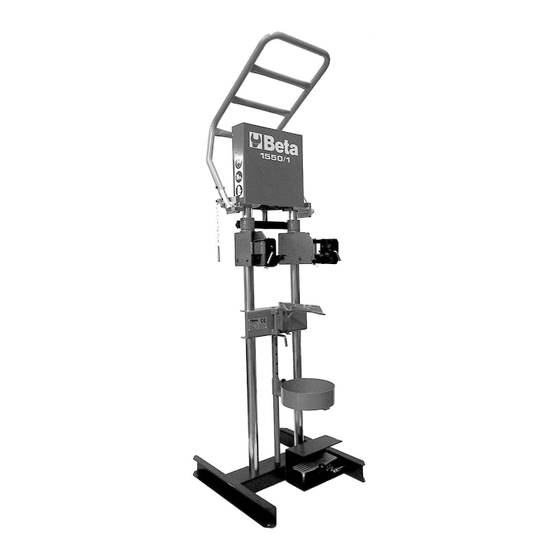
. jest mocno trzymana przez lapy inserire foto (photo 6). Il compressore 1550/1 è dotato di un cilindro pneumatico fissato alla struttura, la cui – opuscic oslone! (photo 7); estensione o compressione, consente la chiusura o il rilascio della molla dell’ammortizzatore. - Page 5 INSTRUKCJA OBSLUGI 1550/1 ISTRUZIONI PER L’USO 1550/1 A. Cilindro pneumatico ROZDZIAL 5 B. Asta di comando C. Bracci porta-griffe YTKOWANIE D. Griffe aggancio molle ammortizzatori E. Supporto inferiore Sciskacz nalezy uzywac wylacznie do sprezyn, dla których zostal F. Morsa registrabile per tenuta zaprojektowany.
-
Page 6: Prescrizioni Di Sicurezza
60 cm Maks. sila nacisku dla cis ´n. 6 bar: 735 kG Il compressore pneumatico 1550/1 è realizzato solo ed esclusivamente per intervenire Maks. sila nacisku dla cis ´n. 8 bar: 900 kG sulle molle degli ammortizzatori dei sistemi di sospensione dei veicoli. Il compressore... -
Page 7: Rozdzial 2
SEZIONE 4 MESSA IN SERVIZIO E CONTROLLI PRELIMINARI 2.2 S ´ RODKI OCHRONNE Fissare il pianale del compressore pneumatico 1550/1 con tasselli ad espansione al pavimento (adeguatamente in piano). Podczas obslugi sciskacza pneumatycznego 1550/1 operator musi uzywac obuwie Prima di iniziare le procedure di seguito riportate, assicurarsi che: ochronne, okulary ochronne i rekawice ochronne. - Page 8 ISTRUZIONI PER L’USO 1550/1 INSTRUKCJA OBSLUGI 1550/1 A. Silownik pneumatyczny SEZIONE 5 B. Cie ˛gno C. Ramiona lap górnych IMPIEGO D. Lapy górne Utilizzare il compressore esclusivamente con le molle ammortizzatori per cui è E. Podpora dolna stato progettato. Ogni utilizzo diverso da quello specificamente indicato è da F.
- Page 9 (foto Sciskacz 1550/1 jest wyposazony w silownik pneumatyczny przymocowany do ramy, który sterowany jest sprezonym powietrzem przy ruchu w obu kierunkach Abbassare la struttura di protezione umozliwiajac zarówno kontrolowane sciskanie jak i zwalnianie sprezyny srubowej (foto 7).
- Page 10 Sciskacz jest bezpieczny dla operatora, pod warunkiem, ze jest uzywany zgodnie z – Riportare la molla nella posizione iniziale. instrukcja dostarczona przez BETA UTENSILI. Solo a questo punto sollevare la struttura di protezione. Dopo avere smontato gli ammortizzatori procedere al rimontaggio nel seguente modo: –...
-
Page 11: Konserwacja I Naprawy S ´ Ciskacza
ISTRUZIONI PER L’USO 1550/1 ROZDZIAL 0 SEZIONE 6 SPIS TRES ´ CI Strony MOVIMENTAZIONE, TRASPORTO E IMBALLO ROZDZIAL 1 WSTE ˛P Queste operazioni sono riservate agli operatori addetti al trasporto e alla 1.1 WSTE ˛P DO INSTRUKCJI movimentazione. 1.2 GWARANCJA Il personale addetto deve indossare adeguate protezioni individuali (guanti e occhiali 1.3 IDENTYFIKACJA S ´... - Page 12 INSTRUCCIONES 1550/1 SECTION 0 SECCIÓN 6 CONTENTS Pages MOVIMIENTO, TRANSPORTE Y EMBALAJE SECTION 1 INTRODUCTION Estas operaciones están reservadas a los operarios destinados al transporte y el 1.1 INTRODUCTION TO MANUAL movimiento. 1.2 WARRANTY El personal destinado a dichas operaciones ha de llevar dispositivos de protección 1.3 IDENTIFICATION OF COMPRESSOR...
-
Page 13: Introduction To Manual
INSTRUCCIONES 1550/1 INSTRUCTIONS 1550/1 SECTION 1 INTRODUCTION 1.1 INTRODUCTION TO MANUAL DEAR CUSTOMER, This manual shall steadily be available to both the operator and the trained technician; in addition, it shall be kept throughout the lifetime of the machine and given up if the machine should be sold. -
Page 14: Identification Of Compressor
(foto 6); The compressor 1550/1 is provided with a pneumatic cylinder fixed to the frame; the cylinder can be stretched or compressed for the shock absorber spring to be shrunk ¡Bájese la estructura de protección or released. - Page 15 INSTRUCCIONES 1550/1 INSTRUCTIONS 1550/1 SECCIÓN 5 A. Pneumatic cylinder B. Control rod UTILIZACIÓN C. Jaws arms D. Jaws for shock absorber springs Utilícese el compresr exclusivamnete con los muelles de amortiguadores para E. Lower support los que ha sido diseñado. Toda utilización diferente de la indicada F.
-
Page 16: Safety Rules
Repítase la operación unas cuantas veces. Do not remove or tamper with the warning labels attached to the compressor 1550/1. Tras llevar a cabo todas las operaciones mencionadas arriba, el compresor neumático Replace any damaged warning labels immediately. -
Page 17: Prescripciones De Seguridad
El operador tendrá que llevar calzado de seguridad, gafas y guantes de protección para poder utilizar el compresor neumático 1550/1. Fix the platform of the pneumatic compressor 1550/1 to the floor (it must be level with Atención: it) by means of screw anchors. - Page 18 INSTRUCTIONS 1550/1 INSTRUCCIONES 1550/1 SECTION 5 A. Cilindro neumático B. Varilla de mando C. Brazos porta-garras D. Garras de enganche muelles de Use the compressor only with the shock absorber springs it has been designed amortiguadores for. If the compressor is used in any way other than the recommended one, it E.
-
Page 19: Declaración De Conformidad Ue
Pull down the protecting structure El compresor 1550/1 está dotado de un cilindro neumático fijado en la estructura, (photo 7)! cuya extensión o compresión permite cerrar o soltar el muelle del amortiguador. - Page 20 El compresor no plantea peligros para el – Take the spring back to the starting position. operador de utilizarse conforme a las instrucciones facilitadas por BETA UTENSILI. Now lift up the protecting structure.
- Page 21 INSTRUCTIONS 1550/1 SECCIÓN 0 SECTION 6 ÍNDICE Páginas HANDLING, TRANSPORT AND PACKAGING SECCIÓN 1 INTRODUCCIÓN These operations must be carried out by the staff responsible for transport and 1.1 INTRODUCCIÓN AL MANUAL handling, wearing suitable personal protective equipment (protective gloves and 1.2 GARANTÍA...
- Page 22 GEBRAUCHSANWEISUNG 1550/1 SECTION 0 KAPITEL 6 SOMMAIRE Page BEFÖRDERUNG, TRANSPORT UND VERPACKUNG SECTION 1 INTRODUCTION Diese Schritte sind dem für Transport und Beförderung zuständigen Personal vorbehalten. 1.1 INTRODUCTION AU MANUEL Das zuständige Personal muss angemessene, individuelle Schutzausrüstung 1.2 GARANTIE (Arbeitshandschuhe, Schutzbrille und Sicherheitsschuhe) tragen.
-
Page 23: Introduction Au Manuel
Le compresseur ne présente aucun danger pour – Die Feder wieder in die Ausgangsposition zurückbringen. l’opérateur s’il est utilisé en respectant les instructions fournies par BETA UTENSILI. Erst jetzt die Schutzvorrichtung anheben! Nachdem die Stoßdämpfer ausgebaut wurden, ist bei deren erneutem Einbau folgendermaßen vorzugehen:... -
Page 24: Identification Du Compresseur
(Foto 6); Le compresseur 1550/1 est muni d’un cylindre pneumatique fixé à la structure dont Die Schutzvorrichtung senken (Foto 7)! l’extension ou la compression, assure la fermeture ou la détente du ressort de l’amortisseur. - Page 25 GEBRAUCHSANWEISUNG 1550/1 MODE D’EMPLOI 1550/1 A. Cylindre pneumatique KAPITEL 5 B. Tige de commande C. Bras porte-griffes EINSATZ D. Griffes fixation ressorts amortisseurs E. Support inférieur Verwenden Sie den Luftfederspanner ausschließlich für die Stoßdämpferfedern, F. Etau réglable de tenue für die er konzipiert wurde. Jegliche andere Verwendung, die von der G.
-
Page 26: Mesures De Securite
Tiefe: 60 cm Max. Schubkraft bei 6 bar: 735 kg Le compresseur pneumatique 1550/1 a été conçu uniquement pour des opérations à Max. Schubkraft bei 8 bar: 900 kg effectuer sur les ressorts des amortisseurs des systèmes de suspension des... -
Page 27: Sicherheitsvorschriften
SECTION 4 MISE EN SERVICE ET CONTROLES PRELIMINAIRES 2.2 SCHUTZEINRICHTUNGEN Fixer le plateau du compresseur pneumatique 1550/1 à l’aide de chevilles expansibles Der Bediener muss beim Einsatz des Luftfederspanners vom Typ 1550/1 au sol (en procédant à la mise à niveau). - Page 28 MODE D’EMPLOI 1550/1 GEBRAUCHSANWEISUNG 1550/1 SECTION 5 A. Luftzylinder B. Führungsspindel UTILISATION C. Haltekrallen-Arme D. Armen für Stoßdämpferfedern Utiliser le compresseur uniquement avec les ressorts amortisseurs pour E. Unteres Stützlager lesquels il a été conçu. Tout autre usage que celui qui est recommandé doit être F.
- Page 29 (photo 6); verbrauchten Patrone. Baisser la structure de protection Der Federspanner vom Typ 1550/1 ist mit einem an der Konstruktion befestigten (photo 7). Luftzylinder ausgestattet, der dank seiner Ausdehnung oder Komprimierung das Spannen oder Entlasten der Stoßdämpferfeder ermöglicht.
- Page 30 Der Federspanner stellt keinerlei Gefahr für den Bediener dar, sofern er Après avoir démonté les amortisseurs, procéder aux opérations de remontage de la entsprechend den von BETA UTENSILI gegebenen Anweisungen eingesetzt wird. façon suivante: – installer la cartouche de rechange ou la tige en fonction du type d’amortisseur;...
- Page 31 MODE D’EMPLOI 1550/1 KAPITEL 0 SECTION 6 INHALTSVERZEICHNIS Seiten MANUTENTION, TRANSPORT ET EMBALLAGE KAPITEL 1 EINLEITUNG Ces opérations sont réservées aux opérateurs chargés du transport et de la 1.1 EINLEITUNG IN DIE BETRIEBSANLEITUNG manutention. Le personnel en question doit prendre les mesures de protection 1.2 GARANTIE...
- Page 32 GEBRUIKSAANWIJZING 1550/1 DEEL 0 DEEL 6 INHOUD Pagina’s VERPLAATSING, TRANSPORT EN VERPAKKING DEEL 1 INLEIDING Deze handelingen moeten uitsluitend door de voor transport en verplaatsing 1.1 INLEIDING AL MANUALE aangestelde bedieners worden uitgevoerd. 1.2 GARANTIE Het aangestelde personeel moet de juiste persoonlijke beveiligingsmiddelen dragen 1.3 IDENTIFICATIE VAN DE COMPRESSOR...
-
Page 33: Deel 1
De compressor biedt geen gevaar voor de bediener indien Hef nu pas het beveiligingshek hij hem volgens de door BETA UTENSILI verstrekte instructies gebruikt. Ga, na het demonteren van de schokdempers voor de hermontage als volgt te werk: –... -
Page 34: Identificatie Van De Compressor
(foto 6); het lege patroon. Verlaag het beveiligingshek (foto 7). De compressor 1550/1 is uitgerust met een pneumatische, op de structuur bevestigde cilinder, waarvan de extension of compressie, de sluiting of de vrijmaking van de veer van de schokdemper bewerkstelligt. -
Page 35: Deel 5
GEBRUIKSAANWIJZING 1550/1 GEBRUIKSAANWIJZING 1550/1 DEEL 5 A. Pneumatische cilinder B. Bedieningspook GEBRUIK C. Kaakarmen D. Kaakhaak schokdemperveren U moet de compressor alleen gebruiken met de schokdempende veren E. Lagere support waarvoor hij is ontworpen. Ieder ander, dan het specifiek hier vermelde gebruik F. -
Page 36: Deel 2
Diepte: 60 cm De luchtdrukcompressor 1550/1 is uitsluitend en alleen vervaardigd om op de veren Max. stootwaarde op 6 Bar: 735 kg van de schokdempers van het veringsysteem van voertuigen te worden gebruikt. De Max.