Beta 1881 Mode D'emploi

Pompes pneumatiques pour huile

Publicité

Les langues disponibles
  • FR

Les langues disponibles

  • FRANÇAIS, page 9

Liens rapides

POMPA PNEUMATICA PER OLIO
PNEUMATIC PUMPS FOR OIL DELIVERY
POMPES PNEUMATIQUE POUR HUILE
PNEUMATISCHE ÖLPUMPE
BOMBA NEUMÁTICA PARA ACEITE
PNEUMATISCHE OLIEPOMP
POMPA PNEUMATYCZNA DO OLEJU
ISTRUZIONI PER L'USO
I
INSTRUCTIONS FOR USE
GB
MODE D'EMPLOI
F
GEBRAUCHSANWEISUNG
D
INSTRUCCIONES
E
GEBRUIKSAANWIJZING
NL
INSTRUKCJA OBSLUGI
PL
1881

Publicité

Table des Matières
loading

Sommaire des Matières pour Beta 1881

  • Page 1 1881 POMPA PNEUMATICA PER OLIO ● PNEUMATIC PUMPS FOR OIL DELIVERY ● POMPES PNEUMATIQUE POUR HUILE ● PNEUMATISCHE ÖLPUMPE ● BOMBA NEUMÁTICA PARA ACEITE ● PNEUMATISCHE OLIEPOMP ● POMPA PNEUMATYCZNA DO OLEJU ● ISTRUZIONI PER L’USO INSTRUCTIONS FOR USE MODE D’EMPLOI...
  • Page 2 Parti Principali e Accessori - Main components and accessories - Principaux composants et Accessoires - Bauteile und Zubehör - Partes Principales y accesorios - Belangrijkste onderdelen en accessoires - Główne części i akcesoria...
  • Page 3: Campo Di Utilizzo

    ISTRUZIONI PER L’USO Descrizione La pompa funziona con aria compressa, pertanto richiede di essere collegata ad un impianto con pressione da 4 a 8 bar. Tutti i componenti hanno subito un trattamento superficiale che li protegge dalla corrosione. Le parti fondamentali della pompa sono: A –...
  • Page 4: Collegamento Pneumatico

    Collegamento tubo di mandata • Utilizzare un tubo da ½” o ¾” di ottima qualità e a norma DIN – SAE, comunque adeguato alla pressione e al liquido da pompare. • Collegare una estremità del tubo T al raccordo di uscita R (filetto G ½”o ¾” sferico) della pompa. •...
  • Page 5: Se L'inconveniente Persiste Rivolgersi Al Fabbricante

    Movimentazione • Il peso e le dimensioni d’ingombro della pompa sono riportate alle pag .24 e 25. • La pompa è pronta all’uso e imballata in maniera tale che nessuna delle sue parti subisca danni durante il trasporto. • L’imballo non deve essere disperso nell’ambiente. •...
  • Page 6: General Recommendations

    INSTRUCTIONS FOR USE Description The pump works with compressed air, therefore it is necessary to connect it to a system operating with a pressure of between 4 and 8 bar. All components have been treated and protected against corrosion. The pump consists of three main components: A - Transmits motion •...
  • Page 7: Pneumatic Connection

    Connecting the delivery pipe • Use a ½” or ¾” pipe of very good quality which conform with DIN-SAE regulations, make sure it is suitable to the pressure and to the liquid to be pumped. • Connect one end of the pipe T to the outlet fitting R (Thread G ½ or ¾”spheric) of the pneumatic pump.
  • Page 8: Transport

    Transport • Weight and overall dimensions of the pump are indicated on page 24 - 25. • The pump is ready for use and is packed in such a way that none of its components can be damaged during transportation. •...
  • Page 9: Secteur D'utilisation

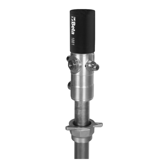
    MODE D’EMPLOI Description La pompe fonctionne avec une alimentation d’air comprimé comprise entre 6 à 8 bars. Tous les composants ont subi un traitement en surface qui les protège de la corrosion. Les parties essentielles de la pompe sont : A –...
  • Page 10: Raccordement Flexible De Refoulement

    Raccordement flexible de refoulement • Utiliser un flexible de ½” ou ¾” de très bonne qualité et à la norme DIN – SAE, dans tous les cas adapté à la pression et au liquide à pomper. • Raccorder une extrémité du flexible T au raccord de sortie R (filet G ½”ou 3/4” sphérique) de la pompe.
  • Page 11: Entretien Périodique

    Manutention • Le poids et les dimensions d’encombrement de la pompe sont indiqués pages 24 - 25. • La pompe est prête à être utilisée et est emballée de façon à ce qu’aucune des parties ne subissent de dommages durant le transport. •...
  • Page 12: Beschreibung

    BEDIENUNGSANLEITUNG Beschreibung Die Pumpe wird mit Druckluft betrieben, also ist für den Betrieb ein entsprechender Druckluftanschluss von 4 bis 8 Bar erforderlich. Alle Komponenten wurden einer Korrosions-Oberflächenbehandlung unterzogen. Die Pumpe hat folgende Hauptkomponenten: A – zur Bewegungsübertragung • Pneumatikmoto • Hubkolben D –...
  • Page 13: Anschließen Des Druckrohrs

    Anschließen des Druckrohrs • Verwenden Sie ein Rohr von ½“ oder ¾“ nach DIN – SAE, das für den verwendeten Druck und die geförderte Flüssigkeit geeignet ist. • Das eine Ende des Rohrs T an den Ausgang R (Gewinde G ½”) der Pumpe anschließen. (Buchstabe R nicht in der Zeichnung!) •...
  • Page 14: Transport Der Pumpe

    Transport der pumpe • Gewicht und Abmessungen der Pumpe siehe Seite 24 - 25. • Die Pumpe wird betriebsbereit und in einer Schutzverpackung ausgeliefert. • Das Verpackungsmaterial ordnungsgemäß entsorgen. • Die Lagerung und der Transport einer neuen Pumpe erfordert keine besonderen Vorsichtsmanah- men und ist mit keinen Risiken und Gefahren verbunden.
  • Page 15: Recomendaciones Generales

    INSTRUCCIONES DE USO Descripción La bomba trabaja con aire comprimido, asi pues es necesario conectarla a un sistema que trabaje entre 4 y 8 bares de presión. Todos los componentes deben de ser protegidos ante la corrosión. La bomba se compone de tres principales componentes. A –...
  • Page 16: Conexión De Manguera De Salida

    Conexión de Manguera de salida • Usar un enchufe de ½“ o ¾“ de máxima calidad , que sea conforme a la norma DIN-SAE asegurandonos que es válido para la presión y el liquido usado. • Colocar dicho enchufe de salida T en la posición R del despiece de la bomba neumática. •...
  • Page 17 Transporte • Los pesos y las medidas estan descritas en las paginas 24 y 25. • La bomba se suministra preparada para su uso en un embalaje que le permitirá llegar a destino sin ser golpeada. • El transporte de estas bombas no requiere ningun cuidado especial, ni tiene ningun riesgo. •...
  • Page 18 GEBRUIKSAANWIJZING Beschrijving De pomp werkt met perslucht en moet daarom op een installatie met een druk van 4 tot 8 bar wor- den aangesloten. Alle onderdelen hebben een oppervlaktebehandeling ondergaan, die ze tegen corrosie beschermt. De belangrijkste onderdelen van de pomp zijn: A -Brengt de beweging over •...
  • Page 19 • Als er geen filter of bodemverbindingsstuk op de pomp is aangebracht, moet er een ruimte van ongeveer 15 mm tussen de bodem van het vat en de aanzuigopening zijn. • Schroef het bovenste gedeelte van ring G1 weer aan tot de pomp vastzit. Aansluiting toevoerslang •...
  • Page 20: Storingen - Oplossing

    Verplaatsing • Het gewicht en de afmetingen van de pomp staan op pag, 24 en 25. • De pomp is klaar voor gebruik en zodanig verpakt dat geen van de onderdelen tijdens het vervoer beschadigd wordt. • De verpakking mag niet in het milieu achtergelaten worden. •...
  • Page 21: Instrukcja Obslugi

    INSTRUKCJA OBSLUGI Opis Pompa działa na sprężone powietrze, dlatego konieczne jest jej podłączenie do układu zasilania z ciśnieniem od 4 do 8 Bar. Wszystkie komponenty zostały zabezpieczone antykorozyjnie. Pompa składa się z czterech głównych części: A – Napędza pompę • Silnik pneumatyczny D –...
  • Page 22 Podłączenie węża podającego • Należy użyć wysokiej jakości węża ½” lub ¾” zgodnego z przepisami DIN-SAE i upewnić się, że jest on odpowiedni do ciśnienia, jakie będzie stosowane i do pompowanej cieczy. • Podłączyć końcówkę węża T do połączenia wylotowego R (gwint G ½ lub ¾”kulisty) pompy. •...
  • Page 23 Transport • Waga i całkowite wymiary pompy są podane na stronach 24 - 25. • Pompa jest gotowa do użytku i jest opakowana w taki sposób, aby żadna z jej części nie została uszkodzona w czasie transportu. • Nie należy wyrzucać opakowania poza miejscami do tego przeznaczonymi. •...
  • Page 24 Dati tecnici - Technical specifications - Caractéristiques techniques - Technische Daten – Datos técnicos - Technische gegevens - Dane techniczne Rapporto di compressione: Compression ratio: Rapport de compression : Verdichtungsverhältnis: Compressieverhouding: Ratio de compresión: Connessione entrata aria: Air inlet connection : Entrée d’air : Lufteinlassöffnung: ¼”...
  • Page 25 Dimensioni Ingombro - Overall dimensions - Dimensions et encombrements – Geräteabmessungen - Dimensiones Totales - Afmetingen - Wymiary A (mm) B (mm) C (mm) D (mm) E (mm) F (mm) G (mm) 1183...
  • Page 28 BETA UTENSILI S.p.A. via Alessandro Volta, 18 - 20050 Sovico (MB) ITALY Tel. +39 039.2077.1 - Fax +39 039.2010742 www.beta-tools.com - info@beta-tools.com...

Table des Matières