LEGRAND 0 026 72 Guide Rapide
Liens rapides
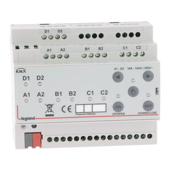
0 026 72/73/74/76/78/79
0 026 78/79
F1 F2
G1 G2 H1 H2
A1 A2 B1 B2
C1 C2 D1 D2
•
Les sorties comptent 5 sorties indépendantes (AB, CD, EF, GH, IJ)
•
Outputs contain 5 independent outputs (AB, CD, EF, GH, IJ)
•
Le uscite contengono 5 uscite indipendenti (AB, CD, EF, GH, IJ)
Éclairage
•
Lighting
•
Illuminazione
•
0 026 72/73
A1A2-B1B2 ... D1D2 A-B-C-D
0 026 74
A1A2-B1B2 ... F1F2
0 026 76
A1A2-B1B2 ... H1H2 A-B-C-D-E-F-G-H
0 026 78/79
A1A2-B1B2 ... J1J2
•
Pour la commande d'éclairage et moteur de volet en courant alternatif AC: Les canaux peuvent être utilisés individuellement, par
exemple : A1 et A2 peuvent être utilisés comme interrupteur pour l'éclairage et B1 et B2 peuvent être utilisés comme commande
de volet AC ...... comme indiqué par les rectangles de couleur rouge dans la figure ci-dessus.
Pour la commande de moteur de volet en courant continu DC, d'échangeur ventilé, de ventilateur et de vanne : Les canaux
consécutifs sont liés entre eux, par exemple : G1-G2 et H1-H2 doivent être utilisés ensemble pour la commande de volet DC ...
comme indiqué par les rectangles de couleur grise dans la figure ci-dessus.
•
For lighting and AC blinds: Channels can be used individually, in example: A1 and A2 can be used as a switch for lighting and B1
and B2 can be used as an AC blind ... as shown with red coloured drawings in above visual.
For DC blind, fan coil, fan control and valve control: Subsequent channels are linked together, in example: G1G2 and H1 H2 have
to be used together for DC blind... as shown with blue coloured drawings in above visual.
•
Per illuminazione e serrande CA: i canali possono essere usati singolarmente, nell'esempio: A1 e A2 possono essere usati come
interruttore per l'illuminazione mentre B1 e B2 possono essere usati come serranda CA ... come mostrato con i disegni colorati in
rosso nella figura sopra.
Per serranda CC, ventilconvettori, controllo ventole e controllo valvole: canali successivi sono collegati tra loro, nell'esempio:
G1 G2 e H1 H2 devono essere usati insieme per una serranda CC ... come mostrato con i disegni colorati in blu nella figura sopra.
0 026 78/79
I1 I2
J1 J2
E1 E2
Volet AC
•
AC blind
•
Serranda CA
•
A-B-C-D-E-F
A-B-C-D-E-F-G-H-I-J AB-CD-EF-GH-IJ
•
Boutons MARCHE/ARRÊT
HAUT/BAS
OUVRIR/FERMER
Volet DC
Commande d'échangeur
•
•
ventilé et de ventilateur
DC blind
•
•
Fan coil fan control
Serranda CC
•
•
Controllo della ventola
del ventilconvettore
AB-CD
AB-CD
AB-CD-EF
AB-CD-EF
AB-CD-EF-GH
AB-CD-EF-GH
AB-CD-EF-GH-IJ
21-30 V=
x = 6-10
1 x 2,5 mm2 / 2 x 1,5 mm2
4 x (Ø 0,6 mm <
< Ø 0,8 mm)
8 mm
- 5°C
+ 45°C
•
Boutons de sélection des canaux
•
Channel Selection Buttons
•
Pulsanti per la selezione del canale
•
Boutons de sélection manuelle
•
Manual Control Buttons
•
Pulsanti per il controllo manuale
•
ON/OFF
•
Pulsanti ON/OFF
UP/DOWN
SU/GIÙ
OPEN/CLOSE
APRI/CHIUDI
Buttons
Commande de vanne
•
Valve contro
•
Controllo della valvola
•
AB-CD
AB-CD-EF
AB-CD-EF-GH
AB-CD-EF-GH-IJ

Manuels Connexes pour LEGRAND 0 026 72


Sommaire des Matières pour LEGRAND 0 026 72
- Page 1 0 026 72/73/74/76/78/79 21-30 V= x = 6-10 1 x 2,5 mm2 / 2 x 1,5 mm2 4 x (Ø 0,6 mm < < Ø 0,8 mm) 8 mm - 5°C + 45°C 0 026 78/79 0 026 78/79 • Boutons de sélection des canaux •...
- Page 2 240 V~ 400 VA 1,6 A 2400 VA 10 A 1800 VA 2400 VA 10 A 4000 VA 17 A 1000 VA 0 026 72/73 • Moteur AC • AC Motor Ventola2 Ventola1 Ventola3 • Motore CA Fan1 Fan2 Fan3 D2 (NA) 0 026 74 Ventola2 •...
- Page 3 0 026 76 DC Motor (F, G) CC Motore (F, G) • Moteur AC • AC Motor • Motore CA DC Motor (F, G) CC Motore (F, G) • Moteur AC • AC Motor • Motore CA...
- Page 4 0 026 78/79 Ventola2 Ventola1 Ventola3 Fan1 Fan2 Fan3 B2 (NA) D2 (NA) DC Motor (D, E) • Moteur AC CC Motore (D, E) • AC Motor • Motore CA...