Publicité
Liens rapides
12/06 AWA2528+1251-2355
Montageanweisung
Istruzioni per il montaggio
Instrukcja montażu
Installation Instructions
Notice d'installation
Инструкция по монтажу
EASY223-SWIRE
A
AWB2528+1251-1589...
b
a
g
f
e
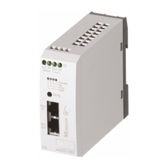
a Anschlussklemmen Gateway, 24 V DC für das Gateway
b Anschlussklemmen AUX, 24 V DC für die Schützspulen
c Buchse Out für SmartWire-Verbindungskabel 6-polig
d DIP-Schalter Betriebsart und Adresskodierung (siehe Tabelle)
e RJ-45-Buchsen Bus In und Bus Out, für easyNet-/CANopen-Anschluss
f Konfigurationstaste Config:
Mit der Konfigurationstaste erstellen Sie die SmartWire-Sollkonfiguration.
Drücken Sie die Config-Taste bis die Ready-LED schnell zu blinken beginnt
(ca. 1 sec.) Dann können Sie die Config-Taste loslassen.
g Status LEDs (von links): Ready, U-AUX, Bus, SmartWire
a Gateway terminals, 24 V DC for gateway
b AUX terminals, 24 V DC for contactor coils
c Out socket for SmartWire connection cable 6-pole
d DIP switch operating mode and address coding (see table)
e RJ-45 sockets Bus In and Bus Out, for easyNet/CANopen connection
f Configuration key Config:
Create the SmartWire setpoint configuration via the configuration key.
Press the Config key until the Ready LED starts flashing quickly (approx. 1 sec.).
Then release the Config key.
g Status LEDs (from left): Ready, U-AUX, Bus, SmartWire
a Bornes passerelle, 24 V CC
b Bornes AUX, 24 V CC pour les bobines contacteur
c Prise femelle de sortie pour câble de connexion SmartWire 6 pôles
d Sélecteur DIP mode de fonctionnement et codage d'adresses (voir tableau)
e Prises femelle RJ-45 bus d'entrée et bus de sortie, pour connexion easyNet/CANopen
f Bouton de configuration Config :
Pour réaliser la configuration de consigne SmartWire. Appuyer sur le bouton
Config jusqu'au clignotement rapide de la DEL Ready (1 sec. env.).
Relâcher ensuite le bouton.
g DEL d'état (de gauche) : Ready, U-AUX, Bus, SmartWire
c
d
Vor Montage/Demontage Steuerspannung abschalten!
Electric current! Danger to life!
Only skilled or instructed persons may carry out the
following operations.
Switch off the control voltage before fitting/removal!
Tension électrique dangereuse !
Seules les personnes qualifiées et averties doivent
exécuter les travaux ci-après. Couper la tension de
commande avant le montage/démontage !
Tensione elettrica: Pericolo di morte!
Solo persone abilitate e qualificate possono eseguire
le operazioni di seguito riportate.
Prima del montaggio/smontaggio, disinserire la
tensione di comando!
Prąd elektryczny! Zagrożenie życia!
Poniższe czynnosci mogą być wykonywane
tylko przez przeszkolony personel.
Wyłącz napięcie sterownicze przed wykonaniem
montażu/demontażu
Электрический ток! Опасно для жизни!
Только специалисты или проинструктированные
лица могут выполнять следующие операции.
Перед монтажом и демонтажем обязательно
отключить напряжение
a Morsetti di collegamento gateway, 24 V DC per il gateway
b Morsetti di collegamento AUX, 24 V DC per le bobine del contattore
c Presa out per cavo di collegamento SmartWire a 6 poli
d Interruttore DIP Modalità di funzionamento e codificazione indirizzo (vedere tabella)
e Presa RJ-45 bus in e bus out, per collegamento easyNet/CANopen
f Tasto di configurazione Config:
Con il tasto di configurazione si attiva la configurazione standard SmartWire.
Premere il tasto Config finché il LED Ready inizia a lampeggiare velocemente
(1 sec. ca.). Quindi si può rilasciare il tasto Config.
g LED di stato (da sinistra): Ready, U-AUX, bus, SmartWire
a Zaciski Gateway, 24 V DC dla Gateway
b Zaciski pomocnicze AUX, 24 V DC dla cewek styczników
c Gniazdo wyjsciowe dla 6-biegunowego kabla łączeniowego SmartWire
d Przełącznik DIP trybu pracy i adresowania (patrz tabela)
e Gniazdo RJ-45 Bus wejsciowe i wyjsciowe, dla przyłączenia easyNet/CANopen
f Przycisk konfiguracyjny Config:
Za pomocą przycisku konfiguracyjnego utwórz konfigurację dla setpoint SmartWire.
Wcisnij przycisk konfiguracyjny aż dioda LED-Ready zacznie szybko błyskać (ok.1s.)
Nastepnie zwolnij przycisk konfiguracyjny.
g Diody LED statusu (od lewej): Ready, U-AUX, Bus, SmartWire
a Терминалы обмена данными, 24 В постоянного тока для шлюза
b Терминалы AUX, 24 В постоянного тока для обмоток контактора
c Выходной разъем для соединительного кабеля SmartWire, 6-полюсн.
d DIP-переключатель рабочих режимов и адресного кодирования (см. табл.)
e Разъемы RJ-45 для входной и выходной шины, для быстрого открытого
соединения easyNet/CANopen
f Клавиша конфигурации Config:
Конфигурация заданной величины SmartWire создается с помощью
клавиши конфигурации. Нажмите клавишу Config и удерживайте ее,
пока светодиод Ready не начнет быстро мигать (примерно 1 с).
Затем отпустите клавишу Config.
g Светодиоды состояния (слева направо): Ready (Готов), U-AUX,
Bus (Шина), SmartWire
A
Lebensgefahr durch elektrischen Strom!
Nur Elektrofachkräfte und elektrotechnisch
unterwiesene Personen dürfen die im Folgen-
den beschriebenen Arbeiten ausführen.
1/12
Publicité

Sommaire des Matières pour Moeller EASY223-SWIRE
- Page 1 Montageanweisung Istruzioni per il montaggio Instrukcja montażu Installation Instructions Notice d’installation Инструкция по монтажу EASY223-SWIRE Lebensgefahr durch elektrischen Strom! Nur Elektrofachkräfte und elektrotechnisch unterwiesene Personen dürfen die im Folgen- den beschriebenen Arbeiten ausführen. Vor Montage/Demontage Steuerspannung abschalten! Electric current! Danger to life! AWB2528+1251-1589…...
- Page 2 1 = ON, 0 = OFF, 1…64 = address setting, (n) DIP single switch numbering # (0/1) the address settings 0 and 1 are evaluated as 127 by the EASY223-SWIRE. 1 = ON, 0 = OFF, 1…64 = réglage d’adresse, (n) numérotation chaque sélecteur DIP # (0/1) les réglages d’adresses 0 et 1 sont analysés par EASY223-SWIRE comme 127.
- Page 3 Sicherheitsvorkehrungen (NOT-AUS) in der äußeren Aux-Beschaltung des Effettuare le misure di sicurezza (arresto d’emergenza) nel circuito aux EASY223-SWIRE und SWIRE-PF vornehmen. esterno del EASY223-SWIRE e del SWIRE-PF. Gateway, Aux i opcjonalny moduł zasilający SmartWire SWIRE-PF Gateway, Aux and optionally used SmartWire power module SWIRE-PF must muszą...
- Page 4 Контроллер: easy800, MFD-CP8…, EC4-200, XC100/200 b Bus: easyNet oder CANopen b Шина: easyNet или CANopen c Passerelle SmartWire : EASY223-SWIRE (Maître SmartWire) c Шлюз SmartWire: EASY223-SWIRE (управляющ. SmartWire) d Câble de connexion SmartWire : SWIRE-CAB-… d Соединительный кабель SmartWire: SWIRE-CAB-…...
- Page 5 (bez żadnej stacji SmartWire, tylko zasilacz) e SmartWire termination connector: SWIRE-CAB-000 e Zacisk łączący SmartWire: SWIRE-CAB-000 a Passerelle SmartWire : EASY223-SWIRE (Maître SmartWire) a Шлюз SmartWire-Gateway: EASY223-SWIRE (управляющ. SmartWire) b Câble de connexion SmartWire : SWIRE-CAB-… b Соединительный кабель SmartWire: SWIRE-CAB-…...
- Page 6 Erstinbetriebnahme mit einem einzelnen EASY223-SWIRE als NET-Teilnehmer – Initial commissioning with a single EASY223-SWIRE as NET station – Première mise en service avec un seul EASY223-SWIRE comme participant NET – Prima messa in servizio con un singolo EASY223-SWIRE come utente NET –...
- Page 7 MFD-CP8-NT, EC4-200 z NET-ID 1 b easy800, MFD-CP8-NT, EC4-200 with NET-ID 1 c Połączenie logiczne z EASY223-SWIRE za pomocą easyNet i stacji 1 c Logical connection with EASY223-SWIRE via easyNet and station 1 a MFD-CP8-NT en mode terminal a MFD-CP8-NT в...
- Page 8 MFD-CP8-NT, EC4-200 z NET-ID 1 b easy800, MFD-CP8-NT, EC4-200 with NET-ID 1 c Połączenie logiczne z EASY223-SWIRE za pomocą easyNet i stacji 1 c Logical connection with EASY223-SWIRE via easyNet and station 1 a MFD-CP8-NT en mode terminal a MFD-CP8-NT в...
- Page 9 – easySoft-CoDeSys ab Version 2.3.5, mit dem aktuellen Service Pack – easySoft-CoDeSys dalla versione 2.3.5, con il Service Pack aggiornato – EDS-Datei zum EASY223-SWIRE zur Verwendung an einem beliebigen – File EDS per EASY223-SWIRE per l’uso su un qualsiasi master CANopen CANopen-Master Passi per la messa in servizio Inbetriebnahmeschritte 1) Azionare il contattore DIP sulla modalità...
- Page 10 LED-Status – LED status – DEL d’état – LED di stato – Diody LED-status - Светодиод состояния Ready-LED Keine Spannungsversorgung für das Gateway und die SmartWire-Teilnehmer vorhanden oder interner Fehler im Gateway. GRÜN dauernd Spannungsversorgung und SmartWire-Konfiguration OK, das SmartWire-Gateway und das zugeordnete, steuernde Gerät mit Schreibzugriff sind im RUN, über easyNet/CAN werden Nutzdaten ausgetauscht.
- Page 11 Bus-LED (easyNet) Kein easyNet-Betrieb GRÜN blinkend Gestörter easyNet-Betrieb. Verkabelungsfehler bzw. der Teilnehmer 1 oder ein konfigurierter und zuvor vorhandener anderer easyNet-Teilnehmer ist ausgefallen. GRÜN dauernd Störungsfreier easyNet-Betrieb No easyNet operation GREEN flashing Faulty easyNet operation. Wiring error or station 1 or a configured and another easyNet station has failed. GREEN permanent Trouble-free easyNet operation ARRET...
- Page 12 Некорректная связь по SmartWire, как минимум одна станция SmartWire более не быстро мигает отвечает (сбой питания, разрыв кабеля). Abmessungen – Dimensions – Dimensioni – Wymiary – [mm] Размеры 12/12 Moeller GmbH, Industrieautomation, D-53105 Bonn Änderungen 12/06 AWA2528+1251-2355 DE13 Doku/Eb © 2006 by Moeller GmbH vorbehalten...