Manfrotto 330B Mode D'emploi
I
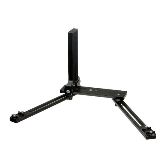
La staffa consente l'uso e l'orientamento di due piccoli lampeggiatori con
l'impiego della fotocamera sia in posizione orizzontale che in verticale.
1
2
ISTRUZIONI PER L'USO
E
1. Sfilare a destra e a sinistra i due bracci "G" allentando le due viti ad anello
"F", in modo da disporre sia il lato aperto delle slitte "H" che la vite ad anello
"D" dallo stesso lato del mirino.
2. Bloccare leggermente i due bracci con le viti ad anello "F".
3. Per fissare la fotocamera, allentare la vite ad anello "D" in modo da
permettere alla piastra "E" di sollevarsi per poter accedere alla vite di
fissaggio fotocamera "C".
4. Centrare il corpo macchina sulla piastra "E", fissare la fotocamera serrando
la vite "C". Fare scorrere la piastra "E" fino a riporla in posizione orizzontale
e quindi bloccarla con la vite "D".
5. Posizionare i due bracci "G" in modo che i lampeggiatori, inseriti nelle slitte
"H" siano rivolti verso il soggetto. Bloccare quindi in posizione con le viti ad
anello "F".
6. Qualora fosse necessario eseguire delle riprese verticali, allentare la vite ad
anello "D" in modo da portare la staffa "E" a 90° portandola all'estremo del
suo supporto (fig. 2) e bloccarla in posizione con la vite "D".
7. Il supporto di base è dotato di attacchi femmina da 1/4" "A" e da 3/8" "B"
per permettere il fissaggio a qualsiasi testa.
GB
The macro bracket support with horizontal and vertical camera attachment
facility is capable of supporting two small camera shoe type flash guns.
1
2
INSTRUCTION
&
1. Slide out left and right side arms "G" by loosening D ring bolts "F", so that
black plastic flash gun attachment shoes "H" face "open end" rearwards.
The brass bolt with D ring "D" should also face rearwards.
2. Partially clamp side arms with D ring bolts "F".
3. If shooting in Landscape format, attach camera to central cork covered
bracket arrangement by loosening brass bolt via D ring"D" so that top part
of central bracket can be hinged up in order to secure camera with platform
screw "C".
4. Arrange camera centrally on cork platform and secure. Now lower hinged
top bracket to base bracket and clamp with D ringed brass bolt "D".
5. Arrange side arms "G" at suitable angle, so that flash guns, when slipped
into receptacle shoes "H" will point at the close-up subject matter. Clamp
both side arms "G" with D ringed bolts "F" from underneath.
6. When subject matter requires "Upright" farmat, loosen D ringed brass bolt
"D" and erect hinged platform bracket "E" to 90°, then slide to opposite end
of bottom bracket and tighten via "D".
Now camera can be attached in Vertical format.
7. The lower central bracket is provided with both 1/4" "A" and 3/8" "B" female
screw sockets for attachment to any tripod head.
Cod. 330,18 - 09/04
Copyright © 2004 Manfrotto Bassano Italy
INSTRUCTIONS
330B
3278
USA

Manuels Connexes pour Manfrotto 330B

Sommaire des Matières pour Manfrotto 330B
- Page 1 Now camera can be attached in Vertical format. 7. The lower central bracket is provided with both 1/4” “A” and 3/8” “B” female 330B 3278 screw sockets for attachment to any tripod head. Cod. 330,18 - 09/04 Copyright © 2004 Manfrotto Bassano Italy...
- Page 2 La barrette permet de fixer facilement un boiter, soit en position verticale, soit en Con fijacion horizontal y vertical da la cámara y para acoplar dos pequeños position horizontale, ainsi que des flashs de petite taille aux deux extrémités sur flashes de pilas.