Ecco EC2014-C Instructions D'installation Et D'utilisation
Les langues disponibles
Les langues disponibles
IMPORTANT! Read all instructions before installing and using. Installer: This manual must be delivered to the end user.
WARNING!
Failure to install or use this product according to manufacturer's recommendations may result in property damage, serious injury, and/
or death to those you are seeking to protect!
Do not install and/or operate this safety product unless you have read and understood the safety information
contained in this manual.
1.
Proper installation combined with operator training in the use, care, and maintenance of emergency warning devices are essential to
ensure the safety of emergency personnel and the public.
2.
Emergency warning devices often require high electrical voltages and/or currents. Exercise caution when working with live electrical
connections.
3.
This product must be properly grounded. Inadequate grounding and/or shorting of electrical connections can cause high current arcing,
which can cause personal injury and/or severe vehicle damage, including fire.
4.
Proper placement and installation is vital to the performance of this warning device. Install this product so that output performance of
the system is maximized and the controls are placed within convenient reach of the operator so that they can operate the system without
losing eye contact with the roadway.
5.
Do not install this product or route any wires in the deployment area of an air bag. Equipment mounted or located in an air bag
deployment area may reduce the effectiveness of the air bag or become a projectile that could cause serious personal injury or death.
Refer to the vehicle owner's manual for the air bag deployment area. It is the responsibility of the user/operator to determine a suitable
mounting location ensuring the safety of all passengers inside the vehicle particularly avoiding areas of potential head impact.
6.
It is the responsibility of the vehicle operator to ensure daily that all features of this product work correctly. In use, the vehicle operator
should ensure the projection of the warning signal is not blocked by vehicle components (i.e., open trunks or compartment doors),
people, vehicles or other obstructions.
7.
The use of this or any other warning device does not ensure all drivers can or will observe or react to an emergency warning signal.
Never take the right-of-way for granted. It is the vehicle operator's responsibility to be sure they can proceed safely before entering an
intersection, drive against traffic, respond at a high rate of speed, or walk on or around traffic lanes.
8.
This equipment is intended for use by authorized personnel only. The user is responsible for understanding and obeying all laws
regarding emergency warning devices. Therefore, the user should check all applicable city, state, and federal laws and regulations. The
manufacturer assumes no liability for any loss resulting from the use of this warning device.
Installation and Operation Instructions
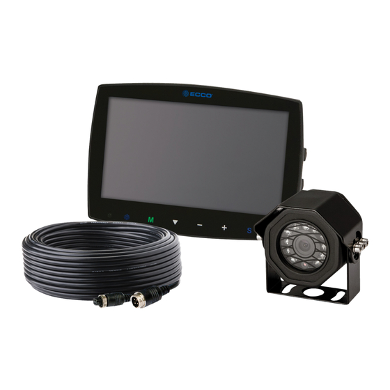
Camera/Monitor System
Page 1 of 10
Table des Matières

Manuels Connexes pour Ecco EC2014-C

Sommaire des Matières pour Ecco EC2014-C
- Page 22 Instructions d’installation et d’utilisation Système moniteur/camèra IMPORTANT! Lisez toutes les instructions avant d’installer et d’utiliser le produit. Installateur : ce manuel doit être remis à l’utilisateur final. AVERTISSEMENT! Lisez toutes les instructions avant d’installer et d’utiliser le produit. Installateur : ce manuel doit être remis à l’utilisateur final. N’installez pas et/ou n’utilisez pas ce produit de sécurité...
-
Page 23: Caractéristiques Techniques
Caractéristiques techniques Caméra EC2014-C 0,33 po. CMOS Couleur Image Pixels effectifs : 725 x 488 Tension nécessaire 12 V Consommation d'électricité Lentille F=2,8 mm/F=2,0 Angle de l'objectif 120° Audio Capteur de lumière Basculement auto noir et blanc DEL infrarouges 11 (visibilité de 10 M max.) Raccord en tire-bouchon : CAM Mâle 4 broches fileté... - Page 24 Écrans Écran ACL EC5603-M de 5,6 po. Écran ACL EC7003-M de 7 po. Image Couleur ACL de 5,6 po., 4:3 Couleur ACL de 7 po., 16:9 Contrôleur Interne/3 caméras Interne/3 caméras Tension 12/24 VCC 12/24 VCC Consommation d'électricité Effet de miroir Oui (via interrupteur moniteur et caméra) Oui (via interrupteur moniteur et caméra) Fonctionnalité...
-
Page 25: Installation, Câblage Et Fonctions
à la limite de leur capacité. Installation Modèle de caméra EC2014-C Important! Installez la caméra à l’endroit offrant le meilleur champ de vision possible sur la zone située immédiatement à l’arrière du véhicule. En général, ce sont les emplacements de montage situés vers le haut du véhicule qui fournissent le meilleur champ de vision possible. - Page 26 Câblage Important! Imperméabilisez tous les raccords, qu’ils se trouvent à l’intérieur ou à l’extérieur du véhicule, en y appliquant un scellant et en les enveloppant dans du ruban isolant. Enroulez fermement le ruban en faisant des chevauchements par demi-largeur pour qu’il n’y ait aucun espacement.
- Page 27 Écrans Modèles EC5603-M et EC7003-M ¡AVERTISSEMENT! Pour éviter les chocs accidentels, N’OUVREZ PAS LE BOÎTIER DU MONITEUR. Sinon, l’intérieur du moniteur sera exposé à des conditions pouvant nuire à son bon fonctionnement. Tout élément prouvant que les composants scellés ont été négligés annulera la garantie.
- Page 28 Instructions d'installation relatives à l'utilisation du socle 1. Choisissez l'emplacement adapté sur le véhicule et fixez le socle. (Figure 6) 2. Fixez le moniteur sur le socle et ajustez l'angle de vue. 3. Installez le pare-soleil et connectez le moniteur à l'aide du câble AV et du câble de conversion d'alimentation (Figure 5) Fixez le support de base sur le véhicule...
- Page 29 Funcionamiento del control remoto: Interrupteur Power Mute (Muet) (Alimentation) Basculement horizontal Basculement vertical Réglage sélection supérieure / Ou sélection d’entrée de caméra PLus de luminosité Moins de luminosité Menu Réglage sélection inférieure / Ou sélection d’entrée de caméra Call (Appel) Mode de l’image Timer (Minuteur) Sélectionnez CAM1/...
- Page 30 Identificacion des pieces: EC5603-M Sélection des menus & mode d’affichage EC7003-M Écran couleur capteur niveau d’ éclairage Sélection de Récepteur IR de signal à Touche de commutation I’appareil photo Haut- Port d'installation pour distance Augmentation de luminosité centrer le support de parleur montage Diminution de la luminosité...
-
Page 31: Normal/Miroir Normal/Miroir Normal/Miroir
Menu Opérations Appuyez sur le bouton Menu de la télécommande ou sur le bouton Menu de l’écran du moniteur. Appuyez plusieurs fois sur le bouton Menu pour passer d’un menu à un autre. Utilisez les touches haut/bas correspondant au canal de la télécommande ou la touche bas de l’écran du moniteur pour sélectionner un menu. - Page 32 833 West Diamond St, Boise, Idaho 83705 Le Service Client États-Unis 800-635-5900 Royaume-Uni +44 (0)113 237 5340 | AUS +61 (0)3 63322444 ECCOESG.com An ECCO SAFETY GROUP™ Brand ECCOSAFETYGROUP.com © 2012 ECCO, Inc. Tous droits réservés. 920-5202-00 Rev. M Page 11 sur 11...