Télécharger Imprimer la page

Publicité

Les langues disponibles
  • FR

Les langues disponibles

Liens rapides

Invective™ 120
Amplifier Head
Operating
Manual
www.peavey.com
1

Publicité

loading

Sommaire des Matières pour Peavey Invective 120

  • Page 1 Invective™ 120 Amplifier Head Operating Manual www.peavey.com...
  • Page 2 (2) I’utilisateur de I’appareil doit accepter tout brouillage radioélectrique subi, même si le brouillage est susceptible d’en compromettre le fonctionnement. Warning: Changes or modifications to the equipment not approved by Peavey Electronics Corp. can void the user’s authority to use the equipment.
  • Page 3 The new sound of metal is here. The Invective™ 120 is the culmination of nearly three decades of refinements and tweaks to Peavey’s legendary 6505 series with an all new clean channel and gobs of peripheral features that are staples for today’s developing musical styles. Designed in close conjunction with Misha Mansoor, of Periph- ery fame, the result is a monster of an amplifier capable of accurately reproducing tons and tons of the sickest tube amp tones imaginable….past, present, and future.
  • Page 4 FRONT PANEL CRUNCH MASTER PRE GAIN POST GAIN STANDBY POWER HIGH VOLUME LEAD NABLE ENABLE CLEAN GATE CRCH PRE GAIN LEAD INPUT HIGH POST THRESHOLD ENABLE ENABLE CHANNEL ENABLE ENABLE (1) POWER SWITCH Applies mains power to the unit. The red POWER STATUS LAMP (3) will illuminate when this switch is in the ON position.
  • Page 5 (6) POST GAIN This control, on the CRUNCH and LEAD channels, sets the overall level of its respective channel. (7) LOW, MID, and HIGH EQ These passive controls, on both the Crunch and Lead channels, provide the signature tone print of the Invective 120.
  • Page 6 Each jack is capable of providing up to 500mA of current. (20 and 21) EFFECTS LOOPS These series loops are used to route the Invective 120 signal path through external effects devices or signal pro- cessors.
  • Page 7 The “microphone” compensation very accurately reproduces the sound of whatever cab you are using in conjunction with the Invective 120. The LEVEL control adjusts the output level of the XLR jack, the TONE control adjusts the extreme high frequency response of the output to accommodate different high frequency drivers in PA systems, and the GROUND LIFT switch is used to break hum-inducing ground loops between the Invective 120 and outboard equipment.
  • Page 8 15 minutes. This should only be carried out by a technically competent person. (29) BIAS ADJUST Adjusting this will vary the bias supply. This should only be adjusted by a qualified Peavey technician, otherwise it could damage your tone, or worse, damage your power tubes.
  • Page 9 FOOTSWITCH (31) Remote Cable An eight-pin DIN connector is provided for connecting the footcontroller to the amplifier IN/FOOT (38) via the cable included in the carton. (32) Preset Mode Switches the footcontroller between NORMAL mode (default, LED off) and PRESET mode (LED red). Other LEDs will be red for Preset Mode, and green for Normal Mode.
  • Page 10 (37) Drive Boost / Preset #5 NORMAL mode: This turns Drive BOOST on and off for the current channel. When switching between chan- nels, this will remember what the last setting was for each. The LED will be green when Drive BOOST is on. PRESET mode: This selects Preset 5.
  • Page 11 LINKING TO ANOTHER AMP AND/OR EFFECTS UNITS WITH THE MIDI OUT You can connect the MIDI Out to the MIDI In of another Invective 120 to synchronize the two amps. With the footswitch connected to the first amp, any changes you make with the footswitch (or front panel) will be dupli- cated on the 2nd amp –...
  • Page 12 MIDI IMPLEMENTATION This amp is designed to be extremely functional with the included 10-button footswitch. The 8-pin footswitch jack also works as a standard 5-pin MIDI input - to go along with the standard 5-pin MIDI output. There are times when the amp will be run with other types of MIDI foot controllers, a PC in the studio, or by an automated rack rig - or linked to another Invective via MIDI.
  • Page 13 MIDI PROGRAM MIDI Program Changes are used to recall presets. Typically a preset will reconfigure all functions on the amp at one time. (Programs 9-11 below are exceptions as they only affect the channel.) NOTE: These messages when recevied will be echoed to the MIDI Out jack for sync’ing with another Invective. NOTE: The first nine presets are your custom presets.
  • Page 14 Factory Map: CHANNEL DRIVE BOOST MASTER BOOST GATE FX LOOP 1 FX LOOP 2 (decimal) (hex)
  • Page 15 Factory Map: CHANNEL DRIVE BOOST MASTER BOOST GATE FX LOOP 1 FX LOOP 2 (decimal) (hex)
  • Page 16 MIDI SYSEX MIDI System Exclusive Commands are used to do all kinds of things that standard commands don’t handle. The Invective uses Sysex for things like backing up or restoring the 9 user presets, or transferring them to a 2nd amp.
  • Page 17 PRESET FORMAT NOTE: commands that send nibbleized preset data send HIGH byte/nibble, then LOW. Preset Bit: 15 14 13 12 2 1 0 Definition: gate gate effects loop 2, 1 n/a CTL 4 master boost 1 for chan 3 1 for chan 1 Overboost 1 = active / CTL 9...
  • Page 18 SPECIFICATIONS Power Amplifier Section: Rated Power & Load: 120W(rms) into 16, 8, or 4 Ohms Power @ Clipping: (Typically @ 5% THD, 1kHz, 120VAC line) 130W(rms) into 16, 8, or 4 Ohms (Bias must be reduced to measure) Frequency Response: +0, -3dB, 50Hz to 20kHz, @ 100W(rms) into 8 Ohms Hum &...
  • Page 19 Effects Return: Impedance: Very High Z, 470K Ohms Designed Level: -10dBV, 300mV(rms) System Hum & Noise @ Nominal Level: (Clean Channel; 20Hz to 20kHz unweighted) Greater than 78dB below rated power Equalization: Custom Low, Mid & High passive type EQ Auxiliary Power Supply Jacks (x2): 9V DC (negative tip) @ 500mA Dimensions: 26.7”...
  • Page 20 Invective™ 120 Tête d'amplificateur Mode d’emploi www.peavey.com...
  • Page 21 9VDC pour l’ é valuation rapide des pédales ou pour alimenter une configuration sans fil. Le tout nouveau Invective™ 120 de Peavey® ..un successeur plus que digne à la suprématie de la conception existante à gain élevé Peavey.
  • Page 22 
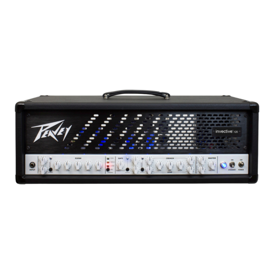
PANNEAU AVANT CRUNCH MASTER PRE GAIN POST GAIN STANDBY POWER HIGH VOLUME LEAD NABLE ENABLE CLEAN GATE CRCH PRE GAIN LEAD INPUT HIGH POST THRESHOLD ENABLE ENABLE CHANNEL ENABLE ENABLE (1) INTERRUPTEUR MARCHE/ARRÊT Met l’unité sous tension. Le VOYANT D’ÉTAT D’ A LIMENTATION rouge (3) s’allume lorsque ce commutateur est sur la position ON.
  • Page 23 (7) EG BASSES, MOYENNE ET AIGUS Ces commandes passives, à la fois sur les canaux Crunch et Lead, fournissent l’ e mpreinte de tonalité de signature de l’Invective 120. (8) PRÉ-GAIN Cette commande, sur les canaux Crunch et Lead, règle le gain/niveau de volume d’ e ntrée de son canal respectif.
  • Page 24 Chaque prise est capable de fournir jusqu’à 500 mA de courant. (20 et 21) BOUCLES D’EFFETS Ces boucles de série servent à acheminer le chemin du signal de l’Invective 120 par des systèmes d’ e ffets externes ou des processeurs de signaux.
  • Page 25 (23) SECTION MSDI Le circuit MSDI exclusif de Peavey fournit un signal direct simulé par microphone à l’ é quipement d’ e nregistre- ment externe et aux mixeurs. La compensation « microphone » reproduit très précisément le son de tout cab que vous utilisez en conjonction avec l’Invective 120.
  • Page 26 (29) RÉGLAGE DE LA POLARISATION Ce réglage peut modifier l’alimentation de polarisation. Il ne doit être réglé que par un technicien Peavey qualifié, autrement cela pourrait endommager votre tonalité, ou pire, endommager vos tubes de puissance. (30) POINTS DE TEST DE POLARISATION Ces points de test de tension sont mis à...
  • Page 27 PÉDALE (31) Câble de télécommande Un connecteur DIN à huit broches est prévu pour raccorder la commande à pédale de l’amplificateur IN/FOOT (38) via le câble inclus dans le carton. (32) Mode Preset (préréglé) Commute la commande à pédale entre le mode NORMAL (par défaut, LED éteinte) et le mode PRESET (LED rouge).
  • Page 28 (37) Commande Boost / Préréglage N° 5 Mode NORMAL : Cela permet d’activer ou de désactiver la commande BOOST pour le canal courant. Lors de la commutation entre les canaux, le dernier réglage pour chacun sera mémorisé. La LED sera verte lorsque la commande BOOST est activée.
  • Page 29 LIAISON À UN AUTRE AMPLI ET/OU À DES UNITÉS D’EFFETS AVEC LA SORTIE MIDI Vous pouvez connecter la Sortie MIDI à l'entrée MIDI d'un autre invective 120 pour synchroniser les deux amplis. Avec la commande à pédale connectée au premier ampli, toutes les modifications que vous effectuez avec le pédalier (ou le panneau avant) seront dupliquées sur le 2ème ampli, si le 2ème ampli est sur le même canal...
  • Page 30 CONFIGURATION DU MIDI Cet ampli est conçu pour être extrêmement fonctionnel avec le pédalier à 10 boutons intégré. La prise de pé- dalier à 8 broches fonctionne aussi comme une entrée MIDI standard à 5 broches - pour correspondre avec la sortie MIDI standard à...
  • Page 31 PROGRAMME MIDI Les changements de programme MIDI sont utilisés pour rappeler les préréglages. Généralement, un préréglage reconfigurera toutes les fonctions de l'amplificateur à un moment donné. (Les programmes 9 à 11 ci-dessous sont des exceptions, car ils n'affectent que le canal.) REMARQUE : Ces messages lorsqu’ils sont reçus seront renvoyés à...
  • Page 32 Carte d’usine : CANAL COMMANDE BOOST MASTER BOOST PORTE BOUCLE EFFET 1 BOUCLE EFFET 2 (décimale) (hex)
  • Page 33 Carte d’usine : CANAL COMMANDE BOOST MASTER BOOST PORTE BOUCLE EFFET 1 BOUCLE EFFET 2 (décimale) (hex)
  • Page 34 MIDI SYSEX Les commandes système MIDI exclusives sont utilisées pour faire toutes sortes de choses que les commandes standard ne gèrent pas. L'Invective utilise Sysex pour des choses comme la sauvegarde ou la restauration des 9 préréglages d'utilisateur, ou leur transfert à un 2ème ampli. REMARQUE : Sauf si indiqué...
  • Page 35 FORMAT PRÉRÉGLÉ REMARQUE : les commandes qui envoient des données préréglées divisées envoient un octet/semi-octet HAUT, puis BAS. Bit préréglé : 15 14 13 12 2 1 0 Définition : porte porte boucle d’ e ffets 2, 1 n/a CTL 4 master boost 1 pour can 3 1 pour can 1 suramplification 1 = active...
  • Page 36 CARACTÉRISTIQUES Section d'amplificateur de puissance : Puissance nominale & charge : 120 W (rms) en 16, 8 ou 4 ohms Puissance @ Ecrêtage : (typiquement @ 5% THD, 1 kHz, ligne 120 VAC) 130 W (rms) en 16, 8 ou 4 ohms (La polarisation doit être réduite à...
  • Page 37 Retour d’ e ffets : Impédance : Très haute Z, 470K ohms Niveau prévu : -10 dBV, 300 mV (rms) Bruit & bourdonnement du système @ niveau normal : (Canal Clean ; 20 Hz à 20 kHz non pondéré) Plus de 78 dB en dessous de la puissance nominale Égalisation : ÉG type passive personnalisé...
  • Page 38 Invective™ 120 Verstärker-Topteil Betriebs- anleitung www.peavey.com...
  • Page 39 Speichern von Voreinstellungen. Wir haben außerdem einen internen, direkten analogen MSDI-Aufnahme-/ Mikrofonausgang und zwei zusätzliche 9-V DC-Versorgungsbuchsen für die schnelle Auswertung von Pedalen oder die Stromversorgung eines drahtlosen Setups. Der komplett neue Peavey® Invective™ 120 ... ist ein mehr als würdiger Nachfolger der Geschichte von Peaveys Überlegenheit im Hochverstärkungsbereich.
  • Page 40 FRONTPLATTE CRUNCH MASTER PRE GAIN POST GAIN STANDBY POWER HIGH VOLUME LEAD NABLE ENABLE CLEAN GATE CRCH PRE GAIN LEAD INPUT HIGH POST THRESHOLD ENABLE ENABLE CHANNEL ENABLE ENABLE (1) AN-/AUS-SCHALTER Versorgt das Gerät mit Netzstrom. Die rote STROMVERSORGUNGSKONTROLLLEUCHTE (3) leuchtet auf, wenn sich dieser Schalter in der Position „ON“...
  • Page 41 (7) LOW, MID, HIGH EQ (FREQUENZAUSGLEICH IM NIEDRIGEN, MITTLEREN und HOHEN BE- REICH) Diese passiven Regler liefern sowohl auf dem Crunch- als auch dem Lead-Kanal den typischen Tondruck des Invective 120. (8) PRE GAIN (VORVERSTÄRKUNG) Dieser Regler legt die Eingangslautstärke/Verstärkung des jeweiligen Kanals für die Crunch- und Lead-Kanäle fest.
  • Page 42 Pedalen oder andere Peripheriegeräte gedacht. Jede Buchse kann bis zu 500 mA Strom liefern. (20 und 21) EFFECTS LOOPS (EFFEKTSCHLEIFEN) Diese Serienschleifen werden verwendet, um den Signalweg des Invective 120 durch externe Effektgeräte oder Signalprozessoren zu leiten. Hinweis: Die Schleifen sind auf dem Signalweg hinter dem Master-Verstärker, aber vor der Gesamtlautstärke angeordnet.
  • Page 43 Mischpulte, das ein Mikrofon simuliert. Der Mikrofonausgleich („microphone“) reproduziert sehr genau den Klang einer beliebigen Verstärkerbox, die Sie in Verbindung mit dem Invective 120 verwenden. Der LE- VEL-Regler stellt den Ausgangspegel der XLR-Buchse ein, der TONE-Regler stellt den Hochfrequenzgang des Ausgangs für verschiedene Hochtontreiber in Lautsprecheranlagen ein, und der GROUND-LIFT-Schalter wird...
  • Page 44 Verstärker wurde mindestens 15 Minuten lang ausgeschaltet. Dies sollte nur von einer technisch kom- petenten Person durchgeführt werden. (29) BIAS ADJUST (VORSPANNUNGSEINSTELLUNG) Diese Steuerung variiert die Vorspannungsversorgung. Sie sollte nur von einem qualifizierten Peavey-Techni- ker angepasst werden, da der Klang sonst beeinträchtigt werden oder, was schlimmer ist, Ihre Endstufenröhren beschädigen werden könnten.
  • Page 45 FUSSSCHALTER (31) Remote Cable (Fernkabel) Ein achtpoliger DIN-Stecker dient dem Anschluss des Fußschalters an den Verstärker IN/FOOT (38) über das in der Verpackung mitgelieferte Kabel. (32) Preset mode (Voreingestellungsmodus) Schaltet den Fußschalter zwischen dem NORMAL-Modus (Standard, LED aus) und dem PRESET-Modus (LED leuchtet rot).
  • Page 46 (37) Drive Boost / Preset # 5 (Zusatzverstärkung/Voreinstellung # 5) NORMAL-Modus: Schaltet die Zusatzverstärkung für den aktuellen Kanal ein- und aus. Wenn Sie zwischen den Kanälen wechseln, bleibt die jeweils letzte Einstellung für die einzelnen Kanäle gespeichert. Die LED leuchtet grün, wenn die Drive-BOOST-Funktion eingeschaltet ist.
  • Page 47 VERBINDUNG ZU EINEM ANDEREN VERSTÄRKER UND/ ODER EFFEKTGERÄTEN MITHILFE DES MIDI-AUSGANGS Sie können den MIDI-Ausgang mit dem MIDI-Eingang eines anderen Invective 120 verbinden, um die beiden Verstärker zu synchronisieren. Ist der Fußschalter mit dem ersten Verstärker verbunden, werden alle Ände- rungen, die Sie über den Fußschalter (oder die Frontplatte) vornehmen, auf dem zweiten Verstärker dupliziert,...
  • Page 48 MIDI-IMPLEMENTIERUNG Dieser Verstärker ist durch den mitgelieferten 10-Tasten-Fußschalter äußerst funktionell ausgelegt. Die 8-polige Fußschalterbuchse fungiert auch als standardmäßiger 5-poliger MIDI-Eingang - passend zum standardmäßi- gen 5-poligen MIDI-Ausgang. Es gibt Situationen, in denen der Verstärker über andere MIDI-Fußsteuerungen, einen Studio-PC oder einen automatisierten Verstärker-Rack betrieben wird - oder über MIDI mit einem ande- ren Invective verbunden ist.
  • Page 49 MIDI-PROGRAMM MIDI-Programmänderungen werden verwendet, um Voreinstellungen abzurufen. In der Regel konfiguriert eine Voreinstellung gleichzeitig alle Funktionen des Verstärkers neu. (Nachfolgende Programme 9-11 sind Ausnah- men, da sie nur den Kanal betreffen.) HINWEIS: Diese Befehle werden nach Empfang in Richtung MIDI-Out-Buchse zurückgegeben, um sie mit einem anderen Invective zu synchronisieren.
  • Page 50 Werkeinstellungen: KANAL DRIVE-BOOST MASTER-BOOST GATE FX-SCHLEIFE 1 FX-SCHLEIFE 2 (dezimal) (hex)
  • Page 51 Werkeinstellungen: KANAL DRIVE-BOOST MASTER-BOOST GATE FX-SCHLEIFE 1 FX-SCHLEIFE 2 (dezimal) (hex)
  • Page 52 SYSEX-MIDI-BEFEHLE Systemexklusive MIDI-Befehle werden für alle möglichen Funktionen verwendet, die nicht durch Standardbe- fehle bewältigt werden. Der Invective verwendet Sysex für das Sichern oder Wiederherstellen der 9 Benutzervor- einstellungen oder die Übertragung auf einen zweiten Verstärker. HINWEIS: Wenn nicht unten angegeben, werden diese Befehle bei Empfang NICHT in Richtung MI- DI-Out-Buchse zurückgegeben.
  • Page 53 VOREINSTELLUNGSFORMAT HINWEIS: Befehle, die „abgespeckte“ voreingestellte Daten senden, senden HIGH-Byte/Nibble und dann LOW-Byte. Voreingestelltes Bit: 15 14 13 12 11 2 1 0 Begriffsbestimmung: Gate Gate Effektschleife 2, 1 n/a CTL 4 Master-Boost 1 für Kanal 3 1 für Kanal 1 Overboost 1 = aktiv / CTL 9...
  • Page 54 TECHNISCHE DATEN Endstufe: Nennleistung & Last: 120 W (Effektivwert) in 16, 8 oder 4 Ohm Strom @ Clipping: (Normalerweise @ 5% THD, 1 kHz, 120 V AC-Leitung) 130 W (Effektivwert) in 16, 8 oder 4 Ohm (Vorspannung muss entsprechend reduziert werden) Frequenzgang: +0, -3 dB, 50 Hz bis 20 kHz bei 100 W (Effektivwert) in 8 Ohm Brummen und Rauschen:...
  • Page 55 Effekterückkehr: Impedanz: Sehr hoch Z, 470 K Ohm Standard-Pegel: -10 dBV, 300 mV (Effektivwert) System-Brummen & -Rauschen bei Nominalpegel: (Sauberer Kanal; 20 Hz bis 20 kHz ungewichtet) Über 78 dB, unterhalb der Nennleistung Entzerrung: Benutzerdefiniert Niedrig, Mittel & Hoch; passiver EQ Hilfsstromversorgungsbuchsen (x2): 9 V DC (negative Spitze) @ 500 mA Abmessungen: 26,7”...
  • Page 56 Invective™ 120 増幅器ヘッ ド 取扱 説明書 www.peavey.com...
  • Page 57 日本語 金属の新風が登場。 Invective™ 120 は、 Peavey 伝説の 6505 シリーズのおおよそ30年にわたる改良と微 調整の集大成です。 今日進化を続ける音楽スタイルの定番となった、 斬新なクリーンチャンネルを搭載 し、 周辺機能も満載。 Periphery で有名なミシャ ・ マンソールの協力による設計で、 過去、 現在そしてこれ から考えられる多数の最大チューブアンプトーンを正確に再生できる、 増幅器のモンスターが完成しまし た。 3つの個別チャンネル (クリーン/クランチ/リード) と、 独立した2つの入力ブースト (1つはクリーン、 も う1つは高ゲインチャンネル用) で、 イマジネーションを自由に活用する音のパレッ トが生まれます。 入力 音を速やかに消音し、 より 「高精度の」 消音特性を実現する、 両方のゲインチャンネル入力では、 他製品を...
  • Page 58 正面パネル CRUNCH MASTER PRE GAIN POST GAIN STANDBY POWER HIGH VOLUME LEAD NABLE ENABLE CLEAN GATE CRCH PRE GAIN LEAD INPUT HIGH POST THRESHOLD ENABLE ENABLE CHANNEL ENABLE ENABLE (1) 電源スイッチ 装置の主電源を入れます。 このスイッチがON (オン) 位置にあると、 赤色電源ステータスランプ (3) .が点灯 します。 (2) スタンバイスイッチ ウォームアップ後すぐに作動するように、...
  • Page 59 (6) ポストゲイン クランチとリード上のこの制御は、 各チャンネルのレベル全体を設定します。 (7) 低、 中および高 EQ クランチとリードチャンネルの両方にあるこれらの受動制御は、 Invective 120 の署名トーンプリントとなり ます。 (8) プレゲイン クランチとリードチャンネルの両方にあるのこの制御は、 各チャンネルの入力音量/ゲインを制御します。 この制御でプリアンプの歪みとサステインを増やします。 (9) ブーストセクション この制御群は、 クランチとリードチャンネルのスイッチ切替可能なブーストセクションの音に指示を出しま す。 アンプの高ゲインセクションを引き上げ、 最大エッジに対応するゲートに対抗する入力音量ブーストで す。 (10) ゲート閾値 クランチとリードチャンネルの両方にあるこのスイッチ切替可能な制御を上げて、 入力ゲートが作用して 入力信号を消音するレベルを制御します。 (11) チャンネル このモーメンタリスイッチで、 3つのチャンネル間での選択が可能になります。 チャンネル アクティベーショ ン LED は、 どのチャンネルがアクティブかを表します。 チャンネルスイッチは、 付属のフッ トスイッチでも切...
  • Page 60 説明は、 本説明書の MIDI セクションを参照してください。 (19) 9VDC 補助電源供給 これらのペダル標準 9VDC (陰極) バレルジャックは、 各種ペダルまたはその他周辺機器にすぐに電源を接 続できるために付属しています。 各ジャックは最大 500mA の電流供給まで対応できます。 (20 と 21) エフェク トループ これらのシリーズループは、 外部エフェク ト機器または信号プロセッサから Invective 120 信号パスをルー ティングするのに使用します。 注記: これらのループは、 マスタブーストの後ですが、 信号パスの主音量の前です。 これで、 マスタブーストが 周囲のエフェク ト トレイルをブースト/カッ トしないようにできます。 (22) マスタブースト...
  • Page 61 (23) セクション 専用 Peavey MSDI 回路は、 マイクシミュレートした直接信号を均衡させ、 録音ギヤとミキサーを取り外しま す。 「 マイク」 補正は Invective 120 とあわせて使用しているキャブの種類には関係なく 、 音を非常に正確に 再生します。 レベル制御は、 XLR ジャックの出力レベルを調節、 トーン制御は、 出力の極度に高い周波数応 答を調節して PA システム内の各種高周波数ドライバーに対応し、 接地リストスイッチは、 Invective 120 と 着脱式装置の間のハム誘発接地ループを遮断するのに使用します。 (24) スピーカー出力 併設の ¼” モノラル (TS) ジャックは、 スピーカーエンクロージャの接続用に付属しています。 インピーダン...
  • Page 62 交換時は、 良質チューブ4本を使用し、 バイアスが下記のとおり、 正しく設定されていることを確認してくだ さい。 V7 と V9 は、 ハーフパワーモードで回路から切り替えされます。 注記:高温になるため、 増幅器の電源を少なく とも15分間オフにしていない場合は、 チューブを交換しない でください。 この作業は、 技術資格のある者のみ実施してください。 (29) バイアス調節 この調節で、 バイアス供給が変わってきます。 この作業は、 Peavey の有資格技術者のみが実施してくださ い。 技術者以外が作業に当たると、 トーンが損傷したり、 悪い場合は、 電源チューブが破損する可能性があ ります。 (30) バイアス テストポイント これらの電圧テストポイントは、 技術者が、 各電源チューブのプレート電流を速やかに確定するために使 用する目的で付属しています。 DC ミリボルト (mV) メーターを使用すると、 所定のチューブについて赤色テ...
  • Page 63 フッ トスイッチ (31) リモートケーブル 8ピン DIN コネクタは、 フッ トコントローラをカートンに付属のケーブルを使用して増幅器イン/フッ ト (38) に接続するために付属しています。 (32) プリセッ トモード フッ トコントローラをノーマル (デフォルト、 LED オフ) とプリセッ トモード (LED 赤色) との間で切り替えを 行います。 他の LED は、 プリセッ トモードでは赤色、 ノーマルモードでは緑色になります。 (10ページの 「プリ セッ トモードの使用」 を参照してください) (33) エフェク トループ 1 / プリセッ ト # 1 ノーマルモード:これでエフェク...
  • Page 64 (37) ドライブブースト / プリセッ ト #5 ノーマルモード:これで、 現在のチャンネルのドライブブースをオン ・ オフにします。 チャンネルの切替時、 それぞれ最後の設定が何かがこれで記憶されます。 ドライブブースがオンの場合、 LED は緑色になります。 プリセッ トモード:これでプリセッ ト5を選択します。 選択した場合、 LED が赤色になります。 (38) チャンネル選択 1 / プリセッ ト #6 ノーマルモード:これでチャンネル1を選択します。 LED は緑色に点灯します。 もう一度押すと、 チャンネルが 前の設定に戻ります。 これで、 スイッチ1つで2チャンネル間の変更が簡単にできます。 プリセッ トモード:これでプリセッ ト6を選択します。 選択した場合、 LED が赤色になります。 (39) チャンネル選択...
  • Page 65 ように (モード/プリセッ トの赤色 LED)、 ブーストが無効なときは 9/マスタブースト LED が点滅します。 (プ リセッ ト9のとき、 赤色と緑色が切り替わることで、 プリセッ ト番号とマスタブーストオンが表示されます)。 MIDI アウトによる別のアンプやエフェク トユニッ トとのリンク MIDI アウトを別の Invective 120 の MIDI インに接続して、 2つのアンプを同期化することができます。 フッ トスイッチを最初のアンプに接続した状態で、 フッ トスイッチ (またはフロントパネル) で行った変更は第2 アンプにコピーされます ー 第2アンプが同じ MIDI チャンネルの場合。 MIDI プログラムセクション (13ペー...
  • Page 66 MIDI 実装 このアンプは10ボタンフッ トスイッチを加えることで機能を高度化するように設計されています。 8ピンフッ トスイッチジャックはまた、 標準 5ピン MIDI インとして機能します - 標準5ピン MIDI アウトに対応。 アンプ を他のタイプの MIDI フッ トコントローラ、 スタジオの PCとともに、 あるいは自動ラックリグで実行する、 ま たは MIDI を介して 別のInvective にリンクされる場合があります。 これは、 他のMIDI デバイスにこのアンプ を合わせるために必要な情報です。 注記:MIDI アウトはデータを別の Invective (機能同期) または PC (リモートコントロールやプリセッ トダン プ時の2ウェイ通信) に送ります。...
  • Page 67 MIDI プログラム MIDI プログラム変更を使用して、 プリセッ トを呼び出します。 一般的に、 プリセッ トは、 アンプ上ですべての 機能を一度に再構成します。 (下のプログラム 9~11 は、 チャンネルのみに影響を及ぼすため、 例外です。 ) 注記:これらのメッセージを受信した場合、 別の Invective と同期する MIDI アウトジャックに反映されます。 注記:はじめの9つのプリセッ トはカスタムプリセッ トです。 フッ トスイッチで保存した内容を呼び出します。 チャンネル ドライブブースト マスタブースト CC 4 ゲート FX LOOP 1 FX ループ 2 (プリセッ...
  • Page 68 ファク トリマップ: チャンネル ドライブブースト マスタブースト ゲート FX ループ 1 FX ループ 2 (十進数) (六進数) 該当なし 該当なし 該当なし 該当なし 該当なし 該当なし 該当なし 該当なし 該当なし 該当なし 該当なし 該当なし 該当なし 該当なし 該当なし 該当なし...
  • Page 69 ファク トリマップ: チャンネル ドライブブースト マスタブースト ゲート FX ループ 1 FX ループ 2 (十進数) (六進数) 該当なし 該当なし 該当なし 該当なし 該当なし 該当なし 該当なし 該当なし 該当なし 該当なし 該当なし...
  • Page 70 MIDI SYSEX MIDI システム専用コマンドは、 標準コマンドが取り扱わない内容をすべて対応するのに使用しま す。 Invective は Sysex を使用して、 9つのユーザープリセッ トをバックアップまたは復元するか、 2番目のア ンプに転送します。 注記:下記事項を除き、 これらのメッセージを受信しても、 MIDI アウトジャックには反映されません。 ただ し、 メッセージに最初のアプリの一致する MIDI チャンネルがない場合、 2番目のアンプが一致した場合に 反映されます。 9つのプリセッ ト ダンプ 要求: F0h MIDI chan - 1 (0~15) (データなし) アンプがこのコマンドを受信すると、 9つのプリセッ トダンプメッセージ (下記参照) を MIDI アウトジャック に送信します。...
  • Page 71 プリセッ トフォーマッ ト 注記:ニブルプリセッ トデータが高バイト/ニブル、 次に低バイトを送信するコマンド。 プリセッ トビッ ト: 15 14 13 12 11 2 1 0 定義: 該当なし ゲート ゲート エフ ェク トループ 2, 1 該当なし CTL 4 マスタブースト チャンネル3は1 チャンネル1は1 オーバーブースト 1 = アクティブ / CTL 9 チャンネル1または2は0 チャンネル2または3は0 チャンネル 3、 2、 1 (該当なし...
  • Page 72 仕様 出力増幅器セクション: 定格出力と負荷 : 120W(rms) から 16、 8、 または 4 Ωへ クリッピング時出力: (一般的に @ 5% THD、 1kHz、 120VAC ライン) 130W(rms) から 16、 8、 または 4 Ω (測定のためバイアス削減が必要) 周波数応答: +0、 -3dB、 50Hz ~ 20kHz、 @ 100W(rms) から 8 Ω ハムとノイズ : 定格出力以下で...
  • Page 73 エフェク ト戻り: インピーダンス:非常に高い Z、 470K Ω 設計レベル:-10dBV、 300mV(rms) システムハムとノイズ @ 公称レベル: (クリーンチャンネル、 20Hz ~ 20kHz 比重なし) 定格出力以下で 78dB 以上 均等化: カスタム低、 中および高受働タイプ EQ 補助出力供給ジャック (x2): 9V DC (陰極) @ 500mA 寸法:26.7” W x 11.8” D x 10.0” H (678mm W x 300mm D x 254mm H) 重量:48.3lbs (21.9kg) 注記:仕様は、...
  • Page 74 Invective™ 120 Cabezal amplificador Manual de operación www.peavey.com...
  • Page 75 Ha llegado el nuevo sonido del metal. El Invective™ 120 es la culminación de casi tres décadas de ajustes y cambios a la legendaria serie 6505 de Peavey con un canal limpio totalmente nuevo una variedad de funciones periféricas que son íconos del estilo musical en evolución de la actualidad. Diseñado conjuntamente con Misha Mansoor, del renombrado Periphery, el resultado es un amplificador excepcional que puede reproducir con precisión toneladas de los tonos de amplificación más difíciles que se pueden imaginar...
  • Page 76 PANEL DELANTERO CRUNCH MASTER PRE GAIN POST GAIN STANDBY POWER HIGH VOLUME LEAD NABLE ENABLE CLEAN GATE CRCH PRE GAIN LEAD INPUT HIGH POST THRESHOLD ENABLE ENABLE CHANNEL ENABLE ENABLE (1) INTERRUPTOR DE ENCENDIDO Aplica corriente de la red a la unidad. La LÁMPARA roja de ESTADO DE ENCENDIDO (3) se enciende cuan- do el interruptor está...
  • Page 77 (7) ECUALIZACIÓN DE GRAVES, MEDIOS, AGUDOS Estos controles pasivos, en los canales de Aplastamiento y Distorsión, proporcionan la impresión del tono exclu- sivo del Invective 120. (8) PRE GANANCIA Este control, en los canales de Aplastamiento y Distorsión, controla el nivel/ganancia del volumen de su canal respectivo.
  • Page 78 500 mA de corriente. (20 y 21) BUCLES DE EFECTOS Estos bucles de serie se utilizan para conducir la ruta de señal del Invective 120 por los dispositivos de efectos externos o los procesadores de señales. Nota: los bucles son posteriores a la amplificación maestra, pero anteriores al volumen maestro en la ruta de señal.
  • Page 79 La compensación del “micrófono” reproduce con precisión el sonido de la cabina que use junto con el Invective 120. El control de NIVEL ajusta el nivel de salida del enchufe XLR, el control de TONO ajusta le respuesta de frecuencia extrema alta de la salida para ajustarse a los diferen- tes controladores de alta frecuencia en los sistemas de anuncios públicos, y el interruptor de ELEVACIÓN DE...
  • Page 80 (29) AJUSTE DE SESGO Este ajuste variará el suministro de sesgo. Solo debe ser ajustado por un técnico calificado de Peavey, o podría dañar su tono o, lo que es peor, dañar sus tubos de potencia. (30) PUNTOS DE PRUEBA DE SESGO Estos untos de prueba de voltaje se incluyen para que los técnicos puedan determinar rápidamente la corrien-...
  • Page 81 PEDAL (31) Cable remoto Se incluye un conector DIN de ocho clavijas para conectar el controlador de pie al amplificador ENTRADA/PIE (38) a través del cable incluido en la caja. (32) Modo predefinido Conmuta el controlador de pie entre el modo NORMAL (predeterminado, LED apagado) y el modo PREDEFI- NIDO (LED rojo).
  • Page 82 (37) Amplificación de transmisión/ Ajuste predefinido N.° 5 Modo NORMAL: Activa y desactiva la AMPLIFICACIÓN del canal actual. Al conmutar entre canales, recordará el último ajuste de cada uno. El LED se encenderá en verde cuando se activa la AMPLIFICACIÓN de transmi- sión.
  • Page 83 CONEXIÓN DE OTRO AMPLIFICADOR Y/O UNIDADES DE EFECTOS CON LA SALIDA DE MIDI Puede conectar la salida de MIDI a la entrada de MIDI de otro Invective 120 para sincronizar los dos amplifica- dores. Con el pedal conectado al primer amplificador, los cambios que realice con el pedal (o el panel delantero) se duplicarán en el segundo amplificador, si el segundo amplificador está...
  • Page 84 IMPLEMENTACIÓN DE MIDI Este amplificador está diseñado para ser extremadamente funciona con el pedal de 10 botones incluido. El enchufe del pedal de 8 clavijas también funciona como entrada MIDI estándar de 5 clavijas, para acoplarse a la salida MIDI estándar de 5 clavijas. En ocasiones, el amplificador funcionará con otros tipos de controladores de pie de MIDI, una PC en el estudio, o por medio de una plataforma automatizada de bastidores, o conectado a otro Invective mediante MIDI.
  • Page 85 PROGRAMA MIDI Los Cambios del programa MIDI se utilizan para seleccionar ajustes predefinidos. Típicamente, un ajuste prede- finido reconfigurará todas las funciones en el amplificador a la vez. (Los Programas 9-11 siguientes son excepcio- nes, ya que solo afectan el canal). NOTA: Estos mensajes, cuando se reciben, se enviarán el enchufe de salida de MIDI para la sincronización con otro Invective.
  • Page 86 Mapa de Fábrica: CANAL AMPLIFICACIÓN DE TRANSMISIÓN AMPLIFICACIÓN MAESTRA COMPUERTA FX BUCLE 1 FX BUCLE 2 (decimal) (hex)
  • Page 87 Mapa de Fábrica: CANAL AMPLIFICACIÓN DE TRANSMISIÓN AMPLIFICACIÓN MAESTRA COMPUERTA FX BUCLE 1 FX BUCLE 2 (decimal) (hex)
  • Page 88 MIDI SYSEX Los comandos exclusivos del sistema MIDI se usan para hacer todos los tipos de cosas que los comandos están- dar no manejan. El Invective usa Sysex para funciones como respaldo o restauración de los 9 ajustes predefinidos del usuario, o para transferirlos a un segundo amplificador. NOTA: Con excepción de lo señalado a continuación, estos mensajes, cuando se reciben, NO se transferirán al enchufe de salida de MIDI.
  • Page 89 FORMATO PREDEFINIDO NOTA: Comandos que envían datos predefinidos divididos HIGH byte/porción, luego BAJO. Bit predefinido: 15 14 13 12 2 1 0 Definición: compuerta compuerta bucle de efectos 2, 1 n/a CTL 4 amplificación maestra 1 para can 3 1 para can 1 Amplificación superior 1 = activo / CTL 9...
  • Page 90 ESPECIFICACIONES Sección del amplificador de potencia: Potencia y carga nominales: 120 W (rms)a 16, 8, o 4 Ohmios Potencia en la limitación: (Típicamente a 5% THD, 1 kHz, línea de 120 VCA) 130 W (rms) a 16, 8, o 4 Ohmios (Se debe reducir el sesgo para medir) Respuesta a la frecuencia: +0, -3 dB, 50 Hz a 20 kHz, a 100 W (rms) a 8 Ohmios...
  • Page 91 Efectos de retorno: Impedancia: Muy alta Z, 470 K Ohmios Nivel diseñado: -10 dBV, 300 mV (rms) Zumbido y ruido del sistema al nivel nominal: (Canal limpio; 20 Hz a 20 kHz sin ponderación) Mayor a 78dB inferior a la potencia nominal Ecualización: Ecualización personalizada baja, media y alta de tipo pasivo Enchufes auxiliares de suministro de energía (x2):...
  • Page 92 Warranty registration and information for U.S. customers available online at www.peavey.com/warranty or use the QR tag below Features and speci cations subject to change without notice. Peavey Electronics Corporation 5022 Hartley Peavey Drive Meridian, MS 39305 (601) 483-5365 FAX (601) 486-1278 Logo referenced in Directive 2002/96/EC Annex IV (OJ(L)37/38,13.02.03 and defined in EN 50419: 2005...