Publicité

Les langues disponibles

Les langues disponibles

Liens rapides

INSTRUCTION MANUAL
Keep this manual in a safe place for future reference
DIRECT-ACTING PRESSURE REDUCING
VALVES FOR STEAM AND/OR AIR
MODEL DR20/A-DR20
EINBAU- UND BETRIEBSANLEITUNG
Gebrauchsanleitung leicht zugänglich aufbewahren
DIREKT WIRKENDE DRUCKREDUZIERVENTILE
FÜR DAMPF UND/ODER DRUCKLUFT
TYP DR20/A-DR20
MANUEL D UTILISATION
Conserver ce manuel dans un endroit facile d'accès
DÉTENDEURS-RÉGULATEURS À ACTION
DIRECTE POUR VAPEUR ET/OU AIR
MODÈLE DR20/A-DR20
DR20
A-DR20
Copyright (C) 2021 by TLV CO., LTD. All rights reserved.

Publicité

Table des Matières
loading

Sommaire des Matières pour TLV DR20

  • Page 1 DIREKT WIRKENDE DRUCKREDUZIERVENTILE FÜR DAMPF UND/ODER DRUCKLUFT TYP DR20/A-DR20 MANUEL D UTILISATION Conserver ce manuel dans un endroit facile d'accès DÉTENDEURS-RÉGULATEURS À ACTION DIRECTE POUR VAPEUR ET/OU AIR MODÈLE DR20/A-DR20 DR20 A-DR20 Copyright (C) 2021 by TLV CO., LTD. All rights reserved.
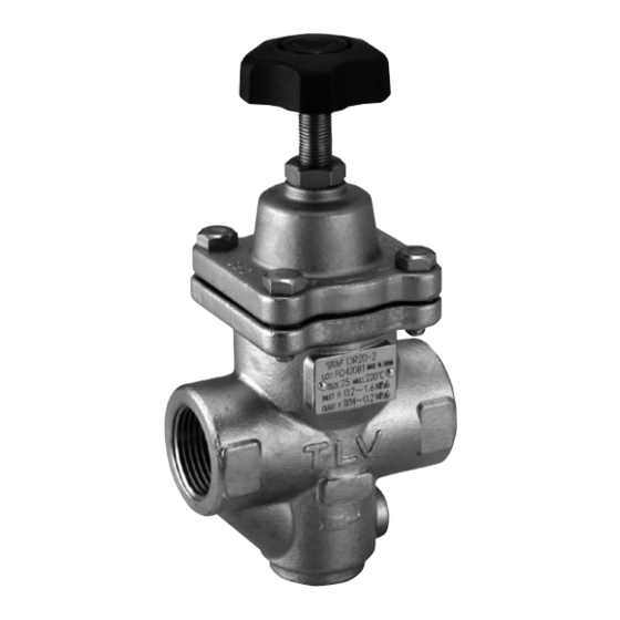
  • Page 2 Keep the manual in a safe place for future reference. The DR20 direct-acting pressure reducing valve for steam and air is capable of reducing from primary pressures of between 0.2 and 1.6 MPaG (30 – 230 psig) to secondary pressures between 0.014 and 1.0 MPaG (2 –...
  • Page 3: Safety Considerations

    • The three types of cautionary items above are very important for safety; be sure to observe all of them, as they relate to installation, use, maintenance, and repair. Furthermore, TLV accepts no responsibility for any accidents or damage occurring as a result of failure to observe these precautions.
  • Page 4: Sicherheitshinweise

    • Diese drei Warnzeichen sind wichtig für Ihre Sicherheit. Sie müssen unbedingt beachtet werden, um den sicheren Gebrauch des Produktes zu gewährleisten und Einbau, Wartung und Reparatur ohne Unfälle oder Schäden durchführen zu können. TLV haftet nicht für Unfälle oder Schäden, die durch Nichtbeachtung dieser Sicherheitshinweise entstehen.
  • Page 5: Règles De Sécurité

    • Ces 3 indicateurs sont importants pour votre sécurité ; observez les précautions de sécurité énumérées dans ce manuel pour l’installation, l’utilisation, l'entretien et la réparation du produit. TLV n’accepte aucune responsabilité en cas d’accident ou de dommage survenant à la suite d'un non-respect de ces précautions.
  • Page 6 ② ⑪ und als Einlage im Hauptventil ⑲ integriert. ⑩ ㉓ Pour le A-DR20 : Le caoutchouc (en ⑨ standard : fluoré) est utilisé sur la surface d'usure. Le caoutchouc est serti dans la vanne principale. ⑦ ⑥ Soft Seat (Fluorine rubber) ⑤...
  • Page 7: Exploded View Einzelteile Pièces Détachées

    Le palier lisse et l'anneau élastique ne peuvent pas être retirés seuls puisqu'ils sont fixés à l'entretoise. Pour remplacer ces pièces, il faut remplacer l'entretoise en entier. Pour le A-DR20 : Le caoutchouc est serti dans la vanne principale et ne peut être enlevé. La vanne principale doit être remplacée.
  • Page 8: Specifications Technische Daten Données Techniques

      Größe/DN   Dimension/DN Applicable Fluids D. Primary Pressure Range Verwendbare Medien   Vordruckbereich Fluide applicables   Plage de pression amont DR20 A-DR20 E. Maximum Operating Temperature Steam, Air   Maximale Betriebstemperatur Dampf, Luft Luft   Température de fonctionnement maximale Vapeur, air F.
  • Page 9 Operating Range Betriebsdaten Plage de fonctionnement DR20-2 DR20-6 DR20-10 Model Typ Modèle Primary Pressure Range 0.2 – 1.6 MPaG 0.6 – 1.6 MPaG Vordruckbereich 2 – 16 barg 6 – 16 barg Plage de pressions amont 30 – 230 psig 85 –...
  • Page 10 5. Piping and Installation • Installation, inspection, maintenance, repairs, disassembly, adjustment and CAUTION valve opening/closing should be carried out only by trained maintenance personnel. • Take measures to prevent people from coming into direct contact with product outlets. • Install for use under conditions in which no freeze-up will occur. •...
  • Page 11 If an on-off valve is required to stop the supply of steam or air to the equipment, install it on the inlet side of the DR20/A-DR20. If a solenoid valve is installed at the outlet of the DR20/A-DR20, it will cause heavy chattering and may lead to damage of the DR20/A-DR20. (When the on-off valve...
  • Page 12: Accessories

    5.7 Piping Supports / Maintenance Space Install the Leave sufficient DR20/A-DR20, paying space for attention to avoid maintenance, excessive load, inspection and bending and vibration. repair. Supporting the inlet and outlet pipes securely is recommended. (6″ ) (6″ ) 5.8 Piping Size / Diffuser If the secondary side flow velocity is expected to be more than 30 m/s (100 ft/s), install a diffuser in order to keep the flow velocity below 30 m/s (100 ft/s).
  • Page 13: Adjustment

    Loosen the locknut adjustment handle  4. Slowly, fully open the shut-off valve at the inlet of the DR20/A-DR20.  5. Slightly open the shut-off valve at the outlet of the DR20/A-DR20.  6. Turn the adjustment handle clockwise until the desired outlet pressure is obtained. Wait   several minutes.
  • Page 14: Inspection And Maintenance

    Check for warping or damage Gaskets Wait for the body to cool before attempting to remove the DR20/A-DR20 from the line. Then remove the DR20/A-DR20 from the piping and secure it in a vise to perform the inspection. 7.1 Disassembling the Adjustment Section...
  • Page 15 Body spring and the screen. Main Valve* * For A-DR20: The rubber is inlaid in the main valve and cannot be removed. The main valve itself must be replaced. 7.4 Cleaning After inspection and removal of any abnormality, clean and reassemble the parts.
  • Page 16 This product is shipped after stringent checks and inspection, and should perform its intended function for a long period of time without failure. However, should there be any problem encountered in the operation of the DR20/A-DR20, Consult the troubleshooting guide below. Problem...
  • Page 17 5. Rohrleitungsführung und Einbauhinweise • Einbau und Ausbau, Inspektion, Wartungs- und Reparaturarbeiten, VORSICHT Öffnen/Schließen von Armaturen, Einstellung von Komponenten, dürfen nur von geschultem Wartungspersonal vorgenommen werden. • In sicherer Entfernung von Auslassöffnungen aufhalten und andere Personen warnen, sich fern zu halten. •...
  • Page 18 Magnetventils auf der Austrittsseite von DR20/A-DR20 kann zu heftigen Schwingungen bzw. Druckstößen führen, die eine Beschädigung von DR20/A-DR20 bewirken können (wenn ein AUF/ZU-Ventil öffnet, ändert sich der Minderdruck von DR20/A-DR20 von 0 auf Einstelldruck, und durchläuft dabei ein Reduktionsverhältnis unterhalb 1:30, was mit DR20/A-DR20 nicht regelbar ist.
  • Page 19 DR20/A-DR20 und dem Verbraucher groß ist, muss der entsprechende Druckverlust bei der Auslegung der Leitung beachtet werden. Rohrerweiterung Länge gerader Leitung 10 d oder länger vor DR20/A-DR20, 15 d oder länger nach DR20/A-DR20 5.9 Druckreduzierung in 2 Stufen Die Druckreduzierung in zwei Stufen wird empfohlen, wenn der benötigte Minderdruck wegen der vorliegenden Betriebsbedingungen mit nur einem Druckminderventil nicht erreicht werden kann.
  • Page 20 6. Einstellung Die beschriebenen Schritte zur Einstellung von DR20/A-DR20 befolgen. Besonders in einem Dampfsystem muss das Druckminderventil DR20 sorgfältig eingestellt werden, um den Dampfverbraucher vor Wasserschlag zu schützen  1. Vor Beginn müssen alle Rohrleitungen durchgeblasen werden.  Das Durchblasen ist besonders wichtig wenn die Leitungen längere Zeit außer Betrieb waren.
  • Page 21: Inspektion Und Wartung

    Faltenbalg Auf Verformung, Risse und Beschädigung prüfen. Dichtungen Auf Verformung oder Beschädigung prüfen Warten, bis das Gehäuse abgekühlt ist. Dann DR20/A-DR20 aus der Rohrleitung ausbauen und zur Inspektion in einen Schraubstock spannen. 7.1 Ausbau der Teile im Einstell-Bereich Haltering* Die Kontermutter lösen und den Einstellgriff Einstellgriff vollständig herausschrauben.
  • Page 22 Hauptventil, Druckfeder und Schmutzsieb aus dem Gehäuse Gehäuse herausnehmen. Hauptventil* * Für A-DR20: Die Kunststoffeinlage im Hauptventil kann nicht entnommen werden. Zum Austausch das Hauptventil ersetzen. 7.4 Reinigung Nach Inspektion und Wartung alle Teile reinigen und das Ventil zusammenbauen. Die folgenden Teile müssen gereinigt werden...
  • Page 23 8. Fehlersuche Unsere Druckminderventile werden einer strengen Endkontrolle mit einer genauen Funktions- prüfung unterzogen. Sollte jedoch trotzdem eine Störung am Druckminderventil DR20/A-DR20 auftreten, gehen Sie bitte nach der folgenden Anleitung vor. Fehler Ursache Gegenmaßnahmen Kein Dampf/keine Luft vorhanden Einlass-/Auslassleitungen und Einlass- Minderdruck /Auslassventil überprüfen...
  • Page 24: Tuyauterie Et Installation Correcte

    5. Tuyauterie et installation correcte • Tout installation, inspection, entretien, réparation, démontage, réglage et ATTENTION ouverture/fermeture de vanne doit être fait uniquement par une personne formée à l'entretien. • Éviter que des personnes n'entrent en contact direct avec les orifices du produit. •...
  • Page 25: Installation D'une Vanne Tor

    Si une vanne TOR est requise pour stopper l’alimentation de vapeur ou d’air du système, il faut l’installer du côté entrée du DR20/A-DR20. Si une électrovanne est installée à la sortie du détendeur, elle entraînera un broutage important et pourrait endommager le piston et la soupape principale.
  • Page 26: Support Des Conduites / Espace D'inspection

    5.7 Support des conduites / Espace d’inspection Installer le Laisser DR20/A-DR20 en suffisamment prenant soin d’éviter d’espace pour toute charge excessive, pouvoir effectuer courbure ou vibration. les inspections et Prévoir des supports les réparations. pour les conduites d’entrée et de sortie.
  • Page 27 6. Réglage Veuillez suivre les procédures suivantes pour régler le DR20/A-DR20. Surtout si le détendeur DR20 est installé sur un système vapeur, il doit être correctement réglé afin de protéger l'équipement contre les coups de bélier.  1. Il est indispensable de purger toutes les conduites à fond.
  • Page 28: Contrôle Et Entretien

    7. Contrôle et entretien Pour garantir une longue durée de vie au DR20/A-DR20, les inspections et entretiens suivants doivent être faits régulièrement, au moins une fois par an. Il est particulièrement important d’effectuer une inspection immédiatement après le premier usage d'une nouvelle ligne, ou bien avant ou après qu’une pièce d'équipement comme un réchauffeur soit mis à...
  • Page 29: Démontage De La Section De La Soupape

    Corps soupape, le ressort hélicoïdal et la crépine. Soupape principale* * Pour le A-DR20 : Le caoutchouc est serti dans la vanne principale et ne peut être enlevé. La vanne principale doit être remplacée. 7.4 Nettoyage Après un examen minutieux, nettoyer et remonter les pièces. Les pièces suivantes doivent être nettoyées :...
  • Page 30: Détection Des Problèmes

    8. Détection des problèmes Ce produit est expédié après avoir subi de nombreux tests et une inspection rigoureuse. Il devrait remplir ses fonctions pendant une longue période sans défaillance. Toutefois, si un problème devait survenir pendant le fonctionnement, consulter le guide de détection des problèmes ci-dessous.
  • Page 31: Product Warranty

    2) Champ d’application de la garantie : TLV CO., LTD. garantit à l’acheteur originel que ce produit est exempt de tout vice de fabrication ou de qualité du matériau. Sous cette garantie, le produit sera réparé ou remplacé, au choix de TLV CO., LTD. sans aucun frais de pièces ou de main d’œuvre.
  • Page 32 Contact your TLV representative or your regional TLV office. Für Reparatur und Wartung: Wenden Sie sich bitte an Ihre TLV Vertretung oder an eine der TLV Niederlassungen. Pour tout service ou assistance technique: Contactez votre agent TLV ou votre bureau régional TLV.

Ce manuel est également adapté pour:

A-dr20

Table des Matières