Publicité
Liens rapides
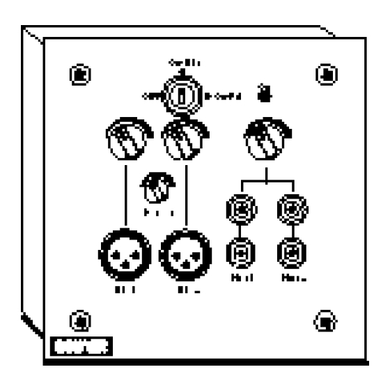
I - DESCRIPTION
La platine AP 104 est un préamplificateur pour
montage encastré ou en saillie sur une paroi (Fig. I
et II).
Elle comporte 4 entrées (2 MIC - 2 AUX) en façade
et une sortie ligne 0dB sur bornier. Plusieurs pla-
tines peuvent être montées en cascade sur une
seule ligne audio. La mise en service est obtenue
par un interrupteur à clé.
Une alimentation extérieure est à prévoir.
II-CARACTERISTIQUES TECHNIQUES
• Alimentation ..................................24V
• Interrupteur à clé 3 positions
Extraction possible de la clé à chaque position :
Position 1 - OFF
Position 2 - ON : entrées MIC et AUX mélangées
Position 3 - ON : entrées MIC prioritaire sur AUX
Chaque platine est livrée avec 2 clés.
Les Clés sont identiques pour toutes les platines.
• Entrées microphone ........................symétriques
Pour micro électrodynamique ou électret, Prise
XLR
Sensibilité ..................................................-55 dB
Bande passante (3 dB)..................55 Hz à 16 kHz
• Entrées Auxiliaire ..........................asymétriques
Prises Cinch double
Sensibilité ..................................................-10 dB
Bande passante (3 dB) ................ 20 Hz à 22 kHz
• Entrée cascadable ............................asymétrique
Entrée sur bornier interne
Niveau nominal..............................................0 dB
• Sortie ligne ............symétrique (transformateur)
Sortie sur bornier interne
Niveau nominal..............................................0 dB
• Priorité MIC/AUX :
Par détection de modulation
Réglage par le bouton "Detect" en façade
Le taux d'atténuation est à prérégler à la mise en
service par PT5, à côté du bornier interne.
Réglage de -6dB à atténuation totale.
• Sortie télécommande :
La platine délivre une télécommande (0V
actif),soit à la mise en service, soit par détection
lier interne (SW1)
• Dimensions ..........................145 x 145 x 45 mm
• Poids ..............................................................1 kg
I - DESCRIPTION
The AP 104 is preamplifier to be surface or flush
mounted to a wall (Fig. I and II).
It offers 4 inputs (2 MIC - 2 AUX) and a 0 dB out-
put on terminal. Several panels may be put in
parallel on a single audio line. A key allows to
switch on the panel.
It is necessary to have an external power sup-
plier.
II - TECHNICAL SPECIFICATIONS
• Power supply ..................................24V
50mA
• Switch ON key with 3 positions
Extraction possible de la clé à chaque position :
Position 1 - OFF
Position 2 - ON : Mic and Aux inputs are mixed
Position 3 - ON : Mic inputs have priority over
Aux inputs. Each panel is provided with 2 keys.
The keys are identical to every panel.
• Mic input ................................................balanced
For electret and dynamic microphone, XLR
socket
Sensitivity ................................................-55 dB
Bandwidth (3 dB) ......................55 Hz to 16 kHz
• Aux input ............................................unbalanced
Dual Cinch sockets
Sensitivity..................................................-10 dB
Bandwidth (3 dB) ...................... 20 Hz to 22 kHz
• Parallel input......................................unbalanced
Input on internal terminal
Nominal level ................................................0 dB
• Line output....................balanced on transformer
Output on internal terminal
Nominal level ................................................0 dB
• MIC/AUX priority :
by detection of modulation
Set up by using "Detect" button
The muting level is achieved by using PT 5
Adjustment of -6 dB up to total muting
• Remote control output :
The panel provides a remote control (OV active),
either by switching ON, or by modulation detec-
tion of the mic selection is mode by using jum-
-
per SW1.
• Dimensions ..........................145 x 145 x 45 mm
• Weight ............................................................1 kg
480, avenue de Paris • 82042 MONT AUBAN CEDEX • FRANCE
Tél : +33 (0)5 63 21 30 00 • Fax : +33 (0)5 63 03 08 26
E-mail : bouyer@bouyer-audio.com • http://www .bouyer-audio.com
A
P
1
A
P
1
PREAMPLIFICATEUR
PREAMPLIFIER
Montage encastré
50mA
Fig. I
Montage en saillie
Fig. II
0
4
0
4
Publicité

Manuels Connexes pour Bouyer AP 104


Sommaire des Matières pour Bouyer AP 104
- Page 1 I - DESCRIPTION Montage encastré La platine AP 104 est un préamplificateur pour The AP 104 is preamplifier to be surface or flush montage encastré ou en saillie sur une paroi (Fig. I mounted to a wall (Fig. I and II).
- Page 2 Relier le blindage, d’une part, à la masse du préamplificateur (socle de la prise Link the screen to the earth of preamplifier (base of DIN or XLR plug) and to DIN ou XLR), et d’autre part à la masse de l’AP 104 (cosse Fig. IV). the earth of AP 104 (terminal Fig. IV) Les sorties S0-S1 attaquent l’entrée symétrique (1 et 3 DIN ou 3 et 2 XLR).