LiftMaster PROTECTOR SYSTEM CPS-UN4 Mode D'emploi
Les langues disponibles
Les langues disponibles
INTRODUCTION
APPLICATION
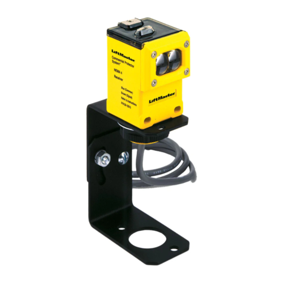
NOTE: The images throughout this manual are for reference and
your product may look different.
The Commercial Protector System is suitable for use in
applications where the photoelectric sensors will be exposed to
moisture. The CPS-UN4 and CPSUN4G are LiftMaster Monitored
Entrapment Protection (LMEP) devices and are compatible with
the following operators:
LiftMaster
Models FDC, FDCL, FDO, and LGE, Medium
Commercial Door
Duty Logic, Logic 3, Logic 4, and Logic 5
Operators
LiftMaster Legacy
Models CSL24V, CSW24V, RSL12V,
Gate Operators
RSW12V, LA400, LA412 and LA500
LiftMaster 2016
Models HCTDCU, LA400PKGU, LA412PKGU,
UL 325 Gate
LA500PKGU, CSL24U, CSW24U, RSL12U,
Operators
RSW12U, CSW200501U, CSW200101U,
SL3000501U, SL3000101U, SL585U family,
and SL595U family
IMPORTANT INFORMATION ABOUT THE
PHOTOELECTRIC SENSOR
Be sure power to the operator is disconnected.
When properly connected and aligned, the photoelectric sensor
will detect an obstruction in the path of its invisible light beam.
If an obstruction breaks the light beam while the door/gate is
closing, the operator will stop and typically reverse to the full open
position.
The sensors must be installed so that the emitter and receiver
sensors face each other across the entrapment zone and the beam
is no more than 6" (15 cm) above the fl oor for a commercial door
and no more than 27.5" (69.8 cm) above grade for a gate for
entrapment protection. Either can be installed on the left or right of
the entrapment zone as long as the sun never shines directly into
the receiver eye lens.
The brackets must be securely fastened to a solid surface such as
the wall framing. If installing in masonry construction, add a piece
of wood at each location to avoid drilling extra holes in masonry if
repositioning is necessary.
The invisible light beam path must be unobstructed. No part of
the gate or door (or door tracks, springs, hinges, rollers or other
hardware) may interrupt the beam while the door/gate is closing.
If it does, use a piece of wood to build out each sensor mounting
location to the minimum depth required for light beam clearance.
For commercial doors, additional photoelectric sensors may
be added at heights greater than 6" (15 cm) above the fl oor for
vehicle/property detection.
COMMERCIAL PROTECTOR SYSTEM
MODELS CPS-UN4 AND CPSUN4G
To prevent possible SERIOUS INJURY or DEATH from a closing
gate or door:
• Entrapment protection devices MUST be installed per the
operator owner's manual for each entrapment zone.
• Be sure to DISCONNECT POWER to the operator BEFORE
installing the photoelectric sensor.
• The gate or door MUST be in the fully opened or closed
position BEFORE installing the LiftMaster Monitored
Entrapment Protection device.
• Correctly connect and align the photoelectric sensor.
• For entrapment protection, install the photoelectric sensor
BEAM NO HIGHER than 6" (15 cm) above the fl oor for door
and 27.5" (69.8 cm) above grade for gate operators.
WARNING: This product can expose you to chemicals including
lead, which are known to the State of California to cause cancer
or birth defects or other reproductive harm. For more information
go to www.P65Warnings.ca.gov
Photoelectric
Sensor
Vehicle/Property Detection
Photoelectric
Sensor
6" (15 cm)
Monitored Entrapment Protection
Facing the door from inside the garage
(installation procedures are the same for all door types).
Photoelectric
Sensors
Invisible Light Beam
Protection Area
27.5"
(69.8 cm)
max.
Photoelectric Sensor
Invisible Light Beam
Protection Area
1
DOOR
Invisible Light Beam
Protection Area
Entrapment Zone
SWING GATE
Invisible Light Beam
Protection Area
Photoelectric
SLIDE GATE
Photoelectric
Sensor
®
Photoelectric
Sensor
Photoelectric
Sensor
6" (15 cm)
Sensors
27.5"
(69.8 cm)
max.

Manuels Connexes pour LiftMaster PROTECTOR SYSTEM CPS-UN4

Sommaire des Matières pour LiftMaster PROTECTOR SYSTEM CPS-UN4
- Page 7 à l’humidité. Les modèles CPS-UN4 et CPSUN4G sont des dispositifs • S’assurer de DÉBRANCHER L’ALIMENTATION à l’actionneur surveillés de protection contre le piégeage LiftMaster compatibles AVANT l’installation du capteur photoélectrique. avec les actionneurs suivants : •...
- Page 8 INSTALLATION ASSEMBLER ET MONTER LES SUPPORTS S’assurer que les supports sont alignés de sorte que les capteurs photoélectriques se fassent face de chaque côté de la zone de piégeage. Les supports peuvent être montés sur le sol, les guides de porte ou au mur. PORTAIL PORTE Monter les capteurs à...
- Page 9 INSTALLATION CONNEXIONS DES CONDUITES 1. Déconnecter l’alimentation de l’actionneur. 2. Se servir d’un raccord étanche aux liquides (commercial de 1.3 cm [1/2 po]) avec une rondelle d’étanchéité pour connecter les capteurs. Les capteurs sont fournis avec des fi ls d’alimentation de 91,4 cm (36 po) de long. Nous recommandons l’utilisation d’une boîte de connexion étanche aux liquides à...
- Page 10 INSTALLATION Pour les actionneurs LOGIC 4 et Installation recommandée pour des portes adjacentes et plus d’un jeu de capteurs photoélectriques. LOGIC 5, une CARTE CPS3 est exigée pour câbler un deuxième ensemble de capteurs à cellule photoélectrique. PORTE NO 1 PORTE NO 2 PORTE NO 3 Détection de véhicules/de la propriété...
- Page 11 CÂBLAGE Les capteurs à cellule photoélectrique peuvent être câblés de manière à fonctionner pour le cycle d’ouverture ou de fermeture, selon l’endroit où ils sont câblés sur le tableau de commande. Consulter le manuel d’installation de votre actionneur de barrière pour plus d’information.
-
Page 12: Dépannage
à l’acheteur initial de ce produit que celui-ci est exempt de tout défaut matériel ou de fabrication pendant une période d’un an suivant la date d’achat. POUR OBTENIR UN SERVICE OU COMMANDER DES PIÈCES DE RECHANGE, COMPOSER : 1-800-528-2806 LiftMaster.com © 2015, LiftMaster All Rights Reserved 01-35688F Tous droits réservés...