Publicité
Liens rapides
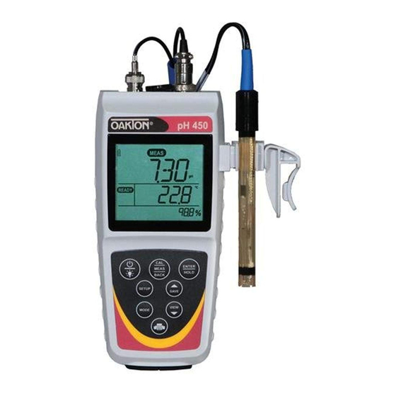
450 Series Waterproof Handheld Meter
Ion Selective Electrode (ISE) Operation Instructions
Model:
pH 450
pH/mV/ISE/Temperature
Getting Started/Connections
After installing (2) AA batteries and/or connecting the optional 110/220
VAC power supply, connect the desired sensors to the corresponding ports.
ATC:
6-Pin ATC
A/C Power
er
Adapter
Output (USB or RS232 – PC
O
o
or Printer Communication)
12 mm and 16 mm probes can utilize the Grip-Clip
sensors to a beaker and to the instrument as needed. The stand can be
extended as shown above or used for wall-mounting.
Keypad Functions
Press once to power ON in the mode that was previously
used. Press again to turn backlight on for one minute or off.
Hold for 3 seconds to power OFF.
Toggle between measurement and calibration modes.
In SETUP mode, BACK serves to return to the previous
menu option or setting.
Confi rm calibration values in CAL mode.
Confi rm selections in SETUP mode.
Freeze or release the measured reading.
Customize instrument settings and preferences.
(See also Setup Programs)
Toggle between available measurement types.
Save measurement into memory. Increase value or scroll
up in SETUP or manual calibration.
Recall saved values from memory. Decrease value or scroll
down in SETUP or manual calibration.
Send output data to printer or computer.
Setup Programs
To access the settings below, press SETUP. Up/down arrows will display the
available options. Press ENTER to accept the desired setting, or BACK to
return to the previous option and/or exit.
Confi guration Options
• Ready indicator ON / OFF / or Automatic HOLD when stable
• Choose ºCelsius or ºFahrenheit
ISE Standard Options
• Choose standard group:
GRP.1 for 0.10, 1.00, 10.0, 100.0 & 1000 (5 points)
GRP.2 for 0.20, 2.00, 20.0, 200.0 & 2000 (5 points)
GRP.3 for 0.50, 5.00, 50.0 & 500.0 (4 points)
• Choose number of calibration points
Select Calibration Due Reminder
• Set number of days from 0-60 for desired parameter
View Calibration Data
• Press ENTER to view each point that is calibrated
View Electrode Data
• Press ENTER to view electrode data
System Settings
• Data Logging:
MANUAL upon key press only.
TIMED interval. Choose (SEC / MIN / HOUR) interval.
• Automatic shut off after 10 minutes. Choose ON or OFF.
• Clock Settings:
Date: Choose USA (MM/DD/YYYY) or Euro (DD/MM/YYYY).
Time: Choose (24HR or 12HR). If 12HR, choose AM or PM.
• Set Printer Type:
CSV (Comma Separated Values) – best format for computer.
Printer (Text) – best format for printer.
Choose Manual (MAN) upon key press or TIMED interval.
BNC:
If timed, choose (SEC / MIN / HOUR).
pH, mV/ORP or
Reset
Ion Selective
• NO. Exits from reset menu options without action.
• FACTORY RESET. Returns all settings except date/time and ATC
calibration to factory default values after ENTER is pressed then
restarts meter.
• DATA RESET. Erases data stored in memory while retaining other
settings after ENTER is pressed.
• CALIBRATION RESET. Erases non-ATC calibration data while retaining
other settings after ENTER is pressed.
ISE Calibration
The pH 450 can measure ion concentration such as ammonia or fl uoride
when using an ion selective electrode (ISE) for the specifi c ion of interest.
See Setup to select one of (3) ISE standard groups based on your intended
standards and range. Use a minimum of 2 values for calibration and prepare
the corresponding ion calibration solutions. For best results always begin
with your lowest standard value, followed by the next lowest standard.
Refer to your Ion Selective Electrode instruction manual for details on
™
to attach one or more
conditioning, storage, maintenance, calibration standard preparation, Ionic
Strength Adjustment, trouble-shooting, etc. Each ISE is unique and requires
care and operation that is specifi c to the electrode and ion of interest.
1. Connect the ISE and press MODE as needed to view ppm. The primary
display will show "- - - -" without a stored ion calibration.
2. Rinse the ISE with clean water and dip into your lowest calibration
standard and stir. Press CAL.
3. Use t/s keys to match the primary display to your desired ion
calibration standard (0.10, 1.0, 10, etc). The secondary display is the
corresponding mV.
4. Press ENTER when the reading is stable to accept the calibration. ERR
indicates that the calibration for the current point was not successful.
This occurs when the slope (mV change between standards) is
<15 mV/decade or >90 mV/decade. The primary display will show the
next highest calibration standard. Use t/s keys to select a different
ion calibration standard if needed.
5. Rinse the ISE then dip into the corresponding calibration standard
and stir. Repeat Steps 3 & 4 as needed. If the number of calibration
points has been reached, the display will return to measurement mode.
Note: The mV/decade slope value will be displayed in during
measurement mode on the lower display upon a successful calibration.
The value corresponds to the slope of the active reading.
mV Offset Adjustment
1. While in mV measurement mode, dip the ORP and ATC sensors into
a solution with a known mV value (i.e. Zobel, Light's, quinhydrone, or
iodide/triiodide) and stir.
2. When the "READY" indicator appears, use up/down arrows to adjust the
primary reading to match the mV value at the measured temperature,
then press ENTER. The meter allows an adjustable maximum value of
±200 mV from the factory default mV value. When an offset has been
stored successfully, R.mV replaces mV.
Temperature Calibration/Manual ATC
1. Press CAL from any measurement, then press MODE.
2. Skip to step 3 for manual ATC, otherwise, dip the temperature sensor
into a solution with a known accurate temperature. The upper display
shows the active temperature while the lower display shows the factory
default temperature without adjustment.
3. Use up/down arrows to adjust the upper display. Press ENTER to accept
the calibration temperature. The maximum adjustable value is ±10 ºC
(or ±18 ºF) from factory default.
(for the parameter being measured)
(for the parameter being measured)
Error Messages
"ERR" will appear when an error condition exists or the incorrect
key is pressed. Common examples include:
• Pressing ENTER during calibration before the "READY" indicator
appears. Wait for the "READY" indicator before pressing ENTER.
• The calibration point was not successful. The allowable mV difference is
15 to 90 mV/decade.
• UR (Under Range) • OR (Over Range)
Intended Use, Maintenance & Precautions
These handheld meters use sensors to detect various parameters for
water-based measurements. For routine maintenance disconnect the
power cord or battery, then dust or wipe the display using a damp cloth.
If necessary, warm water or a mild water based detergent can be used.
Immediately remove any spilled substance from contact with the meter
using the proper cleaning procedure for the type of spill.
• Do not use this equipment in potentially explosive atmospheres.
• Refer to the electrode instructions for use, storage and cleaning.
• Ensure that no liquid enters the instrument.
• Do not use any aggressive cleaning chemicals (solvents or similar
agents).
• There are no user serviceable parts inside. Attempts to service internal
parts may void the warranty.
• Not intended for medical applications or patient use.
• WARNING: No modifi cation of this equipment is allowed.
Instrument Operating Conditions
Operating Ambient Temp.
5 to 45 ºC
Operating Relative Humidity
5 to 85 %, non-condensing
Storage Temp.
-20 to +60 ºC
Storage Relative Humidity
5 to 85 %, non-condensing
Pollution
Degree 2
Overvoltage
Category II
Weight
500 g
Size (L x W x H)
21.15 x 9.87 x 5.85 cm
Regulatory & Safety
CE, TUV 3-1, FCC Class A
Power Rating
DC Input: 9 VDC 1 A
2 x AA (LR6) 1.5 V batteries (replace
Battery Requirement
batteries when battery sign blinks)
Vibration
Shipping/handling per ISTA #1A
Shock
Drop test in packaging per ISTA #1A
Enclosure (Designed To Meet)
IP67 (using rubber covers)
Universal Power Adapter Operating Conditions
Operating Ambient Temp.
0 to 50 ºC
Operating Relative Humidity
0 to 90 %, non-condensing
Storage Temp.
-20 to +75 ºC
Storage Relative Humidity
0 to 90 %, non-condensing
Pollution
Degree 2
Overvoltage
Category II
I/P: 100 - 240 V, 50/60 Hz, 0.3A
Power Rating
O/P: 9 VDC 1 A
Oakton Instruments
625 East Bunker Court, Vernon Hills, IL, 60061, USA
Tel: 1-888-462-5866 • Fax: 1-847-247-2984
info@4oakton.com • www.4oakton.com
68X651905 09/15 Rev1
Publicité

Manuels Connexes pour Oakton 450 Serie

Sommaire des Matières pour Oakton 450 Serie
- Page 1 Confi guration Options default temperature without adjustment. • Ready indicator ON / OFF / or Automatic HOLD when stable Oakton Instruments 3. Use up/down arrows to adjust the upper display. Press ENTER to accept • Choose ºCelsius or ºFahrenheit the calibration temperature. The maximum adjustable value is ±10 ºC...
- Page 2 Cuando un offset se haya guardado exitosamente, Opciones de Confi guración mV es reemplazado por R.mV. Oakton Instruments • Indicador listo ON / OFF / o HOLD (Mantenimiento) automático si estable Calibración de temperatura/ATC Manual 625 East Bunker Court, Vernon Hills, IL, 60061, USA •...
- Page 3 à la pente de la lecture active. Appuyer sur ENTER (Entrée) pour valider le réglage désiré, ou sur BACK Ajustement du décalage mV Oakton Instruments (Retour) pour revenir à l’option précédente et/ou quitter. Options de confi guration 625 East Bunker Court, Vernon Hills, IL, 60061, USA 1.
- Page 4 BACK (Zuruck), um zur vorherigen Option zurückzukehren und/oder 1. Während im mV-Messmodus tauchen Sie die ORP- und ATC-Sensoren zu beenden. Oakton Instruments in eine Lösung mit einem bekannten mV-Wert (z. B. Zobel, Quinhydron Konfi gurationsoptionen 625 East Bunker Court, Vernon Hills, IL, 60061, USA nach Light oder Iodid/Triiodid) und rühren Sie.