Table des Matières
Publicité
Les langues disponibles
Les langues disponibles
Liens rapides
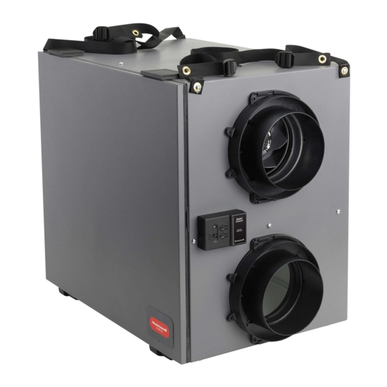
ERV/HRV Ventilation Systems
Systèmes de ventilation VRÉ/VRC
INCLUDED IN THIS BOX
A
1
A
3
Tools required to install ERV/HRV
Aluminum foil tape (UL181B)
Standard screwdriver
Crescent wrench
Hex driver (1/4 in.)
Accessories (not included)
6 in. Dia. insulated duct (VNT5150, VNT5200,
VNT6150 & VNT6200)
6 in. Dia. duct (VNT5150, VNT5200)
Two 6 in. Dia. weather hoods (VNT5150, VNT5200 ,
VNT6150 & VNT6200)
5 in. Dia. insulated flex duct (VNT5070)
5 in. Dia. flex duct (VNT5070)
6 in. Dia. matrix hood, 50063805-009
*
6 in. to 5 in. reducer required
GUIDE D'INSTALLATION
A
2
E
F
(VNT5070)*
PROFESSIONAL INSTALLATION
B
D
G
1
G
G
4
5
OPTIONAL CONTROLS SOLD SEPARATELY
ERV/HRV VNT5150H1000, VNT5150E1000 or
A
1
VNT6150H1000
ERV/HRV VNT5200H1000, VNT5200E1000 or
A
2
VNT6200H1000
ERV/HRV VNT5070H1000 or VNT5070E1000
A
3
Heat/Energy Recovery Core (1)
B
Filter (2)
C
Round Duct Collars (4) (VNT5150 and VNT5200,
D
1
VNT6150 & VNT6200)
Oval Duct Collars (VNT5070)
D
2
Installation Kit (flex included with 5150 and 5200,
E
VNT6150 & VNT6200)
Wall Mount Bracket (VNT5070)
F
Optional Controls: 1 Prestige IAQ Kit, 2 DG115 IAQ Control,
G
3 - Dehumidistat H8908D, 4 - T10 Pro Smart,
5 - 20/40/60 Minute Boost Control,
6 - W8150 Ventilation Control
7 - Vent Boost Remote, 8 - VisionPRO Wi-Fi
GUIDE.
PROFESSIONNELLE.
C
D
1
2
G
G
2
3
G
G
G
6
7
8
69-2480EF-19
Publicité
Chapitres
Table des Matières
Dépannage

Manuels Connexes pour Honeywell Home ERV Série


Sommaire des Matières pour Honeywell Home ERV Série
- Page 1 ERV/HRV Ventilation Systems Systèmes de ventilation VRÉ/VRC PROFESSIONAL INSTALLATION GUIDE. GUIDE D’INSTALLATION PROFESSIONNELLE. INCLUDED IN THIS BOX OPTIONAL CONTROLS SOLD SEPARATELY Tools required to install ERV/HRV ERV/HRV VNT5150H1000, VNT5150E1000 or VNT6150H1000 Aluminum foil tape (UL181B) ERV/HRV VNT5200H1000, VNT5200E1000 or Standard screwdriver VNT6200H1000 Crescent wrench ERV/HRV VNT5070H1000 or VNT5070E1000...
-
Page 2: Installation Checklist
Installation Checklist Liste de vérification pour l’installation Included in This Box Contenu A1 ERV/HRV VNT5150H1000, VNT5150E1000 or A1 VRE/VRC VNT5150H1000, VNT5150E1000 ou VNT6150H1000 VNT6150H1000 A2 ERV/HRV VNT5200H1000, VNT5200E1000 or A2 VRE/VRC VNT5200H1000, VNT5200E1000 ou VNT6200H1000 VNT6200H1000 A3 ERV/HRV VNT5070H1000 or VNT5070E1000 A3 ERV/HRV VNT5070H1000 ou VNT5070E1000 B Heat/Energy Recovery Core B Noyau de récupération de chaleur et d’énergie... -
Page 3: Table Des Matières
ERV/HRV Balanced Ventilation Systems ABOUT THE ERV/HRV VENTILATION SYSTEM MAINTAINENCE Benefits.....................2 Maintenance ................33 Determining Your Ventilation Needs .........3 Cleaning Steps ................34 Specifications ................4 Troubleshooting ................35 External Control Options ............13 OS and Parts List ..............38 Parts Illustration: VNT5150, VNT5200, VNT6150 & VNT6200 ............39 INSTALLATION Parts Illustration: VNT5070 ..........40 Install to Fit Your Application ..........14... -
Page 4: About The Erv/Hrv Ventilation System
About the ERV/HRV Ventilation System The ERV/HRV Balanced Ventilation System provides improved indoor air quality through its high performance and efficiency. Benefits • Ventilation with sensible heat recovery (ERV and HRV) • Ventilation with latent heat recovery (ERV only) • Simplified mounting (hanging) •... -
Page 5: Determining Your Ventilation Needs
Determining Your Ventilation Needs How much fresh air do you need? Good air quality is based in part on the capacity of the home’s ventilation system. Usually, the unit’s capacity is measured in CFM (Cubic Feet per Minute) or L/s (Liters per second) of fresh air being distributed in the living space. -
Page 6: Specifications
Specifications Dimensions in inches (mm) of VNT5150, VNT5200, VNT6150 and VNT6200 FRONT CLEARANCE OF 25 INCHES (635 MM) IS REQUIRED FOR SERVICING UNIT. ALL DUCT CONNECTIONS ARE 6 IN. (150 MM). VNT5150H1000, VNT5150E1000 or VNT6150H1000: H = 22 1/2 in. (572 mm), W = 11 1/2 in. (295 mm), L = 29 1/2 in. (749 mm) VNT5200H1000, VNT5200E1000 or VNT6200H1000: H = 22 1/2 in. - Page 7 Specifications (continued) VNT5150H1000 Ventilation Performance Gross Air Flow External Static Pressure Net Supply Air Flow Supply Exhaust in. W.C. VNT5150H1000 AIR FLOW (L/S) EXTERNAL EXTERNAL STATIC STATIC PRESSURE PRESSURE (IN. W. C) (PA) NET SUPPLY AIR FLOW M32358A AIR FLOW (CFM) VNT5150H1000 Energy Performance Average Sensible...
- Page 8 Specifications (continued) VNT5200H1000 Ventilation Performance Gross Air Flow External Static Net Supply Air Flow Pressure Supply Exhaust in. W.C. VNT5200H1000 AIR FLOW (L/S) EXTERNAL EXTERNAL STATIC STATIC PRESSURE PRESSURE (IN. W. C) (PA) NET SUPPLY AIR FLOW AIR FLOW (CFM) M32354 VNT5200H1000 Energy Performance Average...
- Page 9 Specifications (continued) VNT5150E1000 Ventilation Performance Gross Air Flow External Static Pressure Net Supply Air Flow Supply Exhaust in. W.C. VNT5150E1000 AIR FLOW (L/S) EXTERNAL EXTERNAL STATIC STATIC PRESSURE PRESSURE (IN. W. C) (PA) NET SUPPLY AIR FLOW M32370A AIR FLOW (CFM) VNT5150E1000 Energy Performance Average Sensible...
- Page 10 Specifications (continued) VNT5200E1000 Ventilation Performance Gross Air Flow External Static Net Supply Air Flow Pressure Supply Exhaust in. W.C. VNT5200E1000 AIR FLOW (L/S) EXTERNAL EXTERNAL STATIC STATIC PRESSURE PRESSURE (IN. W. C) (PA) NET SUPPLY AIR FLOW M32369A AIR FLOW (CFM) VNT5200E1000 Energy Performance Average Sensible...
- Page 11 Specifications (continued) VNT5070H1000 Ventilation Performance Gross Air Flow External Static Net Supply Air Flow Pressure Supply Exhaust in. W.C. VNT5070H1000 AIR FLOW (L/S) EXTERNAL EXTERNAL STATIC STATIC PRESSURE PRESSURE (IN. W. C) (PA) NET SUPPLY AIR FLOW AIR FLOW (CFM) M33685 VNT5070H1000 Energy Performance Average...
- Page 12 Specifications (continued) VNT5070E1000 Ventilation Performance Gross Air Flow External Static Net Supply Air Flow Pressure Supply Exhaust in. W.C. VNT5070E1000 AIR FLOW (L/S) EXTERNAL EXTERNAL STATIC STATIC PRESSURE PRESSURE (PA) (IN. W. C) AIR FLOW (CFM) M33684 VNT5070E1000 Energy Performance Average Sensible Apparent...
- Page 13 Specifications (continued) VNT6150H1000 Ventilation Performance Gross Air Flow External Static Pressure Net Supply Air Flow Supply Exhaust in. W.C. VNT6150H1000 AIR FLOW (L/S) EXTERNAL EXTERNAL STATIC STATIC PRESSURE PRESSURE (IN. W. C) (PA) NET SUPPLY AIR FLOW M34365 AIR FLOW (CFM) VNT6150H1000 Energy Performance Average Sensible...
- Page 14 Specifications (continued) VNT6200H1000 Ventilation Performance Gross Air Flow External Static Net Supply Air Flow Pressure Supply Exhaust in. W.C. VNT6200H1000 AIR FLOW (L/S) EXTERNAL EXTERNAL STATIC STATIC PRESSURE PRESSURE (IN. W. C) (PA) NET SUPPLY AIR FLOW M34366 AIR FLOW (CFM) VNT6200H1000 Energy Performance Average Sensible...
-
Page 15: External Control Options
External Control Options The ERV/HRV unit may be used with one of the following external controls: T10 Pro Smart Thermostat • Controls both heating/cooling and ventilation. • Ventilation programming for time of day or Ashrae standards. • Optional ventilation lockouts for high/low temp or humidity conditions using Internet weather when registered to the app. -
Page 16: Install To Fit Your Application
This application uses a devoted duct system for the supply and the exhausting of stale air accumulated in the home. Honeywell Home recommends installing fresh air grilles in all bedrooms and living areas and to exhaust the stale air from the bathroom, kitchen, and laundry room. - Page 17 NOTE: For the minimum distance between the fresh air connection and the forced air system, check with your local building codes and forced air system manufacturer. NOTE: For dwellings with multiple forced air systems, Honeywell Home recommends one ERV/HRV unit per system.
- Page 18 Install to Fit Your Application (continued) Exhaust and Supply in the Return TO LIVING SPACE FORCED AIR SYSTEM HRV / ERV M28985 When using this application make sure that there is a minimum of 6 feet between the fresh air and exhaust air connections of the ERV/HRV unit in the return air duct.
-
Page 19: Installation Steps
Installation Steps Installation Kit Ensure that you have all of the following installation items: 4 Round Duct Collars (VNT5150, VNT5200, Installation Kit: VNT6150 & VNT6200) • 2 Flexible 6 in. Vinyl Ducts (VNT5150, VNT5200, VNT6150, VNT6200) • 1 Condensation Drain Line (10 in.) •... - Page 20 Installation Steps (continued) Hanging the VNT5150, VNT5200, VNT6150 or VNT6200 The ERV/HRV unit enables you to save time and effort by offering a simplified hanging system. TIP: Removing the core unit makes installation easier since the unit weighs less without the core inside. 1.
- Page 21 Installation Steps (continued) Mounting the VNT5070 1. Fix the control module bracket to the top of the 2. Slide the control module onto the bracket VNT5070 using the supplied mounting screws. using the key holes. 3. Fix the wall mount bracket to two 2x4s or to 4.
- Page 22 Installation Steps (continued) Installing the flex duct to the ERV/HRV TIP: Honeywell Home recommends using approximately 16 inches of flexible duct (supplied in kit with VNT5150, VNT5200, VNT6150 and VNT6200) between the unit and the rigid duct for noise dampening. The flex duct is mounted to the unit the same way as the insulated flex.
- Page 23 Installation Steps (continued) Installing the condensation drain line Insert the threaded drain adapter through the bottom of the unit and hand tighten the plastic nut supplied with the drain kit. Use a wrench to tighten the nut another half turn to ensure a complete seal.
-
Page 24: Connecting The Power Cord
Avoid connecting the unit to the wall receptacle with an extension cord. Honeywell Home does not recommend the use of an extension cord. Ensure that the receptacle’s polarization is correct. NOTE: If the LED light on the ERV/HRV control panel remains green, the motors do not energize, and the controls do not operate;... - Page 25 Installation Steps (continued) Optional Matrix hood (50063805-009) installation for fresh air and exhaust air NOTE: Only for applications up to 115 CFM maximum speed. Higher airflow rates are limited by higher static pressures and the potential of cross-contamination between the supply and exhaust air streams.
-
Page 26: Automated Defrost
Automated Defrost The ERV and HRV units are equipped with an automatic defrost feature to eliminate any ice build up on the core. • Automatic defrost is initiated once every hour when the fresh air supply temperature drops to 23°F (-5°C) or colder. -
Page 27: Wiring With Remote Controls
Wiring (continued) Wiring with Remote Controls CONT mode - Ventilator runs continuously on low speed. A ventilation call from a control boosts the ventilator into high speed. INT mode - The ventilator is OFF until a ventilation call from a wall control turns it on in high speed.. Controls Wiring THM5421R (24 VAC) - Page 28 Wiring (continued) INTERLOCK TIMER RLY1 Follow this diagram LVC – L1 General Ventilator Wiring (not interlocked POWERED with equipment fan) COM PORT VENTILATOR THERMOSTAT Vectouch CASE GND REMOTES VENTILATION CONTACTS FURNACE 24-VOLT TERMINAL BLOCK ERV/HRV is used in conjunction with a conventional HEAT/COOL thermostat or other wall control. M28990A INTERLOCK TIMER...
- Page 29 Wiring (continued) VENT Follow this diagram if using VENT DG115 IAQ Control. DEHUM DEHUM M28993 Follow this diagram if using a Dehumidistat. M28994 EARD6TZ AT120 Follow this diagram if using a W8150 Ventilation Control XFMR W8150A FAN TIMER M28995A ERV/HRV Ventilation Systems 69-2480EF—19...
-
Page 30: Control Panel
Wiring (continued) Follow this diagram if using the 20/40/60 Minute Boost Control Timer. Note: Multiple timers can be wired in parallel. M28996 Control Panel The control panel has a 3-position selector switch Speed – and “ ” and “ ” buttons for speed control. The color Control of the LED indicator indicates the current function of the selector switch. -
Page 31: Speed Control Used As A Mode Control
Control Panel (continued) Speed Control used as a Mode Control When the LED indicator is green, the selector switch functions as a Mode Selector. The selections are: • INTER (Intermittent): When the selector switch is in the intermittent position the unit will run only when there is a call for ventilation by any external control. - Page 32 Balancing Steps (continued) a. Use a pitot tube or flow station to measure the air flow in the fresh air duct and exhaust air FRESH AIR DUCT STALE AIR DUCT (LEFT) (RIGHT) duct. (For the VNT5070, make airflow measurements by following the procedure on page 30.) b.
-
Page 33: Balancing Reset
Balancing Reset NOTE: Once balancing is completed, balancing cannot be changed without resetting the unit. To reset: Speed 1. Press the (+) and (–) buttons simultaneously for 10 seconds. Control 2. Indicator light will turn yellow at 5 seconds. Open for 3. - Page 34 Airflow Measurements - VNT5070 only (continued) PRESSURE PORT MAGNEHELIC EXHAUST AIR HIGH HIGH FRESH AIR MAGNEHELIC M33131 Pre & Post Balancing Steps a. Install the flexible duct inner liner (vapor barrier) over the collar and seal with tape, mastic, etc. Note-flexible insulation should be pulled back and away from the duct collar to allow access to pressure ports.
-
Page 35: Maintenance
Maintenance Quarterly or as Needed Filters. Four times per year or as needed, vacuum the filters. Replace filters as needed. Annually or as Needed Inside the Unit. Once a year or as needed, clean the interior of the unit (walls and drain pan) with a mild and non abrasive soap. -
Page 36: Cleaning Steps
Cleaning Steps 2. Open the side door panel by opening the two latches on the top of the side panel and lowering the panel to its fully open position Remove both 1. Disconnect the AC power from the unit or the filters from the top left and right sides of the wall. -
Page 37: Troubleshooting
Troubleshooting CAUTION: Servicing the ERV/HRV unit with its electrical circuitry can cause personal injury. Always make sure that power to the unit is disconnected prior to making any connections. Failure to disconnect the power could result in electrical shock. Service should only be performed by a qualified service technician. - Page 38 Troubleshooting (continued) Problem Possible Cause or Test Procedure Solution Symptom • HRV/ERV • Dehumidistat of • Disconnect all wall controls • Ensure all wall controls operating the wall controls from unit and Speed Control only on high activated. • Ensure all other wall controls wire connections speed, no •...
- Page 39 Troubleshooting (continued) Problem Possible Cause or Test Procedure Solution Symptom • Exhaust Fan • Wiring of fans • Unplug unit, remove access • Ensure wiring activated incorrect on HVC panel from Exhaust Fan (right corresponds to wiring Supply Fan Controller motor mount) .
-
Page 40: Os And Parts List
OS and Parts List OS List OS Number Controls Ventilator Type VNT5070H1000 VNT5070E1000 VNT5150H1000 VNT5150E1000 VNT5200H1000 VNT5200E1000 VNT6150H1000 VNT6200H1000 Parts List (see illustration on page 39 or page 40 for figure number references) Fig. Description VNT5070 VNT5150 VNT5200 VNT6150 VNT6200 Polypropylene HRV Core 50063805-001 50053952-001... -
Page 41: Parts Illustration: Vnt5150, Vnt5200, Vnt6150 & Vnt6200
Parts Illustration (VNT5150, VNT5200, VNT6150 & VNT6200) See the Parts List table on page 38 for items referenced by figure numbers 1 through 16 in the exploded illustration below. M34367 ERV/HRV Ventilation Systems 69-2480EF—19... -
Page 42: Parts Illustration: Vnt5070
Parts Illustration (VNT5070) See the Parts List table on page 38 for items referenced by figure numbers 1 through 11 in the exploded illustration below (VNT5150 and VNT5200). NOT SHOWN M33093 ERV/HRV Ventilation Systems 69-2480EF—19... -
Page 43: 5-Year Limited Warranty
5-Year Limited Warranty Resideo warrants this product to be free from defects in workmanship or materials, under normal use and service, for a period of five (5) years from the date of first purchase by the original purchaser. If at any time during the warranty period the product is determined to be defective due to workmanship or materials, Resideo shall repair or replace it (at Resideo’s option). - Page 44 ERV/HRV Ventilation Systems 69-2480EF—19...
-
Page 45: Systèmes De Ventilation Équilibrée Vre/Vrc
Systèmes de ventilation équilibrée VRE/VRC À PROPOS DU SYSTÈME DE VENTILATION VRE/VRC ENTRETIEN Avantages ..................44 Entretien ..................74 Évaluez vos besoins en matière de ventilation ..45 Nettoyage ..................75 Caractéristiques ................46 Dépannage ..................76 Commandes externes en option ........55 Liste des modèles et des pièces ........79 Illustration des pièces (VNT5150, VNT5200, VNT6150 et VNT6200) ............80 INSTALLATION... -
Page 46: À Propos Du Système De Ventilation Vre/Vrc
À propos du système de ventilation VRE/VRC Le système de ventilation équilibrée améliore la qualité de l’air intérieur grâce à sa haute performance et son efficacité. Avantages • Ventilation avec récupération de la chaleur sensible (VRE et VRC) • Ventilation avec récupération de la chaleur latente (VRE seulement) •... -
Page 47: Évaluez Vos Besoins En Matière De Ventilation
Évaluez vos besoins en matière de ventilation De quelle quantité d’air frais avez-vous besoin? Une bonne qualité d’air dépend en partie de la capacité du système de ventilation de la maison. On mesure habituellement la capacité d’un appareil en pi /min (pieds cubes par minute) ou en l/s (litres par seconde) d’air frais redistribué... -
Page 48: Caractéristiques
Caractéristiques Dimensions en mm (pouces) du VNT5150, VNT5200, VNT6150 et VNT6200: UN DÉGAGEMENT DE 635 MM (25 PO) EST NÉCESSAIRE DEVANT L’APPAREIL POUR SON ENTRETIEN. TOUS LES RACCORDS DE CONDUIT ONT UN DIAMÈTRE DE 150 MM (6 PO). VNT5150H1000, VNT5150E1000 ou VNT6150H1000 : H = 572 mm (22,50 po), l = 295 mm (11,50 po), L = 749 mm (29,50 po) VNT5200H1000, VNT5200E1000 ou VNT6200H1000 : H = 572 mm (22,50 po), l = 422 mm (16,50 po), L = 749 mm (29,50 po) MF28919A Dimensions en pouces (mm) du VNT5070 :... -
Page 49: Caractéristiques (Suite)
Caractéristiques (suite) Performance du VNT5150H1000 en matière de ventilation Débit d’air brut Pression statique externe Débit d’air fourni net Débit d’air fourni Sortie po c.e. /min /min /min VNT5150H1000 DÉBIT D’AIR (l/s) PRESSION PRESSION STATIQUE STATIQUE EXTERNE EXTERNE (po c.e) (Pa) DÉBIT D’AIR FOURNI NET MF32358A... - Page 50 Caractéristiques (suite) Performance du VNT5200H1000 en matière de ventilation Débit d’air brut Pression statique Débit d’air fourni net externe Débit d’air fourni Sortie po c.e. /min /min /min VNT5200H1000 DÉBIT D’AIR (l/s) PRESSION PRESSION STATIQUE STATIQUE EXTERNE EXTERNE (Pa) (po c.e) DÉBIT D’AIR FOURNI NET DÉBIT D’AIR (pi /min)
-
Page 51: Débit D'air Fourni Net
Caractéristiques (suite) Performance du VNT5150E1000 en matière de ventilation Débit d’air brut Pression statique externe Débit d’air fourni net Débit d’air fourni Sortie po c.e. /min /min /min VNT5150E1000 DÉBIT D’AIR (l/s) PRESSION PRESSION STATIQUE STATIQUE EXTERNE EXTERNE (Pa) (po c.e) DÉBIT D’AIR FOURNI NET MF32370B DÉBIT D’AIR (pi... - Page 52 Caractéristiques (suite) Performance du VNT5200E1000 en matière de ventilation Débit d’air brut Pression statique Débit d’air fourni net externe Débit d’air fourni Sortie po c.e. /min /min /min VNT5200E1000 DÉBIT D’AIR (l/s) PRESSION PRESSION STATIQUE STATIQUE EXTERNE EXTERNE (po c.e) (Pa) DÉBIT D’AIR FOURNI NET MF32369B∑...
- Page 53 Caractéristiques (suite) Performance du VNT5070H1000 en matière de ventilation Débit d’air brut Pression statique Débit d’air fourni net externe Débit d’air fourni Sortie po c.e. /min /min /min VNT5070H1000 DÉBIT D’AIR (l/s) PRESSION PRESSION STATIQUE STATIQUE EXTERNE EXTERNE (po c.e) (Pa) DÉBIT D’AIR FOURNI NET DÉBIT D’AIR (pi3/min)
- Page 54 Caractéristiques (suite) Performance du VNT5070E1000 en matière de ventilation Débit d’air brut Pression statique Débit d’air fourni net externe Débit d’air fourni Sortie po c.e. /min /min /min VNT5070E1000 DÉBIT D’AIR (l/s) PRESSION PRESSION STATIQUE STATIQUE EXTERNE EXTERNE (po c.e) (Pa) DÉBIT D’AIR FOURNI NET DÉBIT D’AIR (pi3/min)
- Page 55 Caractéristiques (suite) Performance du VNT6150H1000 en matière de ventilation Débit d’air brut Pression statique externe Débit d’air fourni net Débit d’air fourni Sortie po c.e. /min /min /min VNT6150H1000 DÉBIT D’AIR (l/s) PRESSION PRESSION STATIQUE STATIQUE EXTERNE EXTERNE (po c.e) (Pa) DÉBIT D’AIR FOURNI NET MF34365...
- Page 56 Caractéristiques (suite) Performance du VNT6200H1000 en matière de ventilation Débit d’air brut Pression statique Débit d’air fourni net externe Débit d’air fourni Sortie po c.e. /min /min /min VNT6200H1000 DÉBIT D’AIR (l/s) PRESSION PRESSION STATIQUE STATIQUE EXTERNE EXTERNE (po c.e) (Pa) DÉBIT D’AIR FOURNI NET MF34366...
-
Page 57: Commandes Externes En Option
Commandes externes en option Le VRE/VRC peut être utilisé avec l’une des commandes externes suivantes : Thermostat intelligent T10 Pro • Règle à la fois le chauffage-refroidissement et la ventilation. • Programmation de la ventilation selon l’heure du jour ou les normes Ashrae. -
Page 58: Installation Selon Votre Utilisation
Honeywell Home recommande l’installation de grilles à air frais dans tous les espaces habités (dont les chambres à coucher) et d’évacuer l’air vicié des salles de bain, de la cuisine et de la salle de lavage. -
Page 59: Installation Selon Votre Utilisation (Suite)
REMARQUE : Pour connaître la distance minimale nécessaire entre le raccord d’air frais et le système à air pulsé, consultez les codes du bâtiment locaux et le fabricant du système à air pulsé. REMARQUE : Dans les habitations comportant plusieurs systèmes à air pulsé, Honeywell Home recommande l’utilisation d’un VRE/VRC par système. -
Page 60: Évacuation Et Apport Dans La Conduite De Retour
Installation selon votre utilisation (suite) Évacuation et apport dans la conduite de retour VERS LES ESPACES HABITÉS VRE SYSTÈME À AIR PULSÉ VRC / VRE MF28985 Si vous choisissez cette configuration, assurez-vous que les raccords des conduits d’air frais et d’air vicié du VRE/VRC au conduit de retour d’air sont situés à... -
Page 61: Procédure D'installation
Procédure d’installation Trousse de quincaillerie Assurez-vous d’avoir les articles suivants en main avant d’installer le produit : 4 colliers de conduit ronds (VNT5150, Trousse de quincaillerie : VNT5200, VNT6150 et VNT6200) • 2 gaines flexibles en vinyle de 6 po (VNT5150, VNT5200, VNT6150 et VNT6200) •... -
Page 62: Procédure D'installation (Suite)
Procédure d’installation (suite) Suspension du VRE/VRC (VNT5150, VNT5200, VNT6150 et VNT6200) Le système de suspension simplifié du VRE/VRC permet une installation rapide et facile. CONSEIL : Le fait de retirer le noyau allège l’appareil et facilite l’installation de ce dernier. 1. -
Page 63: Montage Du Vnt5070
Montage du VNT5070 1. Attachez le support du module de commande 2. Faites glisser le module de commande sur en haut du VNT5070 à l’aide des vis de le support en utilisant les boutonnières. montage fournies. 3. Attachez le support de montage mural à deux 4. -
Page 64: Installation De La Gaine Flexible Au Vre/Vrc
Procédure d’installation (suite) Installation de la gaine flexible au VRE/VRC CONSEIL : Honeywell Home recommande d’utiliser 40,64 cm (16 po) de gaine flexible (fournie dans la trousse avec VNT5150, VNT5200, VNT6150 and VNT6200) entre l’appareil et le conduit rigide afin d’atténuer le bruit. -
Page 65: Installation Du Tuyau D'évacuation Des Condensats
Procédure d’installation (suite) Installation du tuyau d’évacuation des condensats Insérez l’adaptateur de tuyau d’évacuation fileté sous l’appareil et resserrez à la main l’écrou en plastique fourni dans l’ensemble du tuyau d’évacuation. Utilisez une clé pour serrer l’écrou d’un demi-tour supplémentaire afin d’assurer l’étanchéité du raccord. Installez le tuyau d’évacuation de condensation en poussant le tube de plastique transparent autour de l’adaptateur de tuyau. -
Page 66: Cordon D'alimentation Du Vre/Vrc
IMPORTANT : Ne branchez pas encore le cordon d’alimentation dans le mur. Prise murale Honeywell Home recommande que l’appareil soit branché à une prise réservée de 120 V c.a. Évitez d’utiliser une rallonge électrique pour brancher l’appareil à une prise murale. -
Page 67: Installation De La Hotte À Matrice Pour L'air Frais Et L'air Évacué
Procédure d’installation (suite) Installation de la hotte à matrice pour l’air frais et l’air évacué REMARQUE : Réservé aux applications d’une vitesse maximale de 115 pi3/min. Les débits d’air supérieur sont limités par des pressions statiques supérieures et le potentiel de contamination croisée entre les flux d’air d’arrivée et d’évacuation. -
Page 68: Dégivrage Automatique
Dégivrage automatique Les appareils VRE et VRC sont munis d’une fonction de dégivrage automatique afin d’éliminer la glace susceptible de se former sur le noyau. • Lorsque la température de l’air frais qui entre dans le système est inférieure à -5 °C (23 °F) ou moins, la fonction de dégivrage automatique se met en marche une fois l’heure. -
Page 69: Câblage Pour Un Fonctionnement Avec Commande À Distance
Câblage (suite) Câblage pour un fonctionnement avec commande à distance Mode CONT (continu) : Le ventilateur fonctionne en continu à basse vitesse; une commande augmente ensuite la vitesse. Mode INTER (intermittent) : Le ventilateur est éteint jusqu’à ce qu’on le mette en marche en haute vitesse, à partir d’une commande murale. - Page 70 Câblage (suite) Suivez ce schéma pour ALIMENTATION câblage général DU VENTILATEUR du ventilateur (sans verrouillage avec THERMOSTAT le ventilateur de CONTACTS l’équipement). DE BORNIER BLOC DE RACCORD 24 VOLTS POUR L’APPAREIL DE CHAUFFAGE MF28990 Le VRE/VRC est utilisé de concert avec un thermostat à commande de chauffage et de refroidissement classique ou un autre type de commande murale.
- Page 71 Câblage (suite) VENT. Suivez ce schéma si vous VENT. utilisez un Régulateur DÉSHUM numérique DG115 IAQ. DÉSHUM MF28993 Suivez ce schéma si vous utilisez un déshumidistat. M28994 EARD6TZ Suivez ce schéma si vous utilisez un régulateur W8150. AT120 XFMR W8150A MINUTERIE MF28995A Suivez ce schéma si vous...
-
Page 72: Panneau De Commande
Panneau de commande Le panneau de commande dispose d’un sélecteur Speed à trois positions et de boutons « + » et « – » pour Control régler la vitesse. La couleur du voyant DEL indique à quelle fonction est réglé le sélecteur. Open for •... -
Page 73: Procédure D'équilibrage
Procédure d’équilibrage REMARQUE : Avant l’équilibrage, assurez-vous que le ventilateur du système CVCA est en marche (si l’appareil VRE/VRC est connecté à un tel système). a. Assurez-vous que le sélecteur de vitesse est à la position INTER ou CONT. b. Appuyez simultanément sur les boutons + et – simultanément pendant 5 secondes jusqu’à ce que le voyant DEL vire au jaune, ce qui indique que vous êtes au mode équilibrage. -
Page 74: Réinitialisation De L'équilibrage
Réinitialisation de l’équilibrage REMARQUE : L’appareil doit être réinitialisé avant chaque nouvelle procédure d’équilibrage. Réinitialisation : Speed Control 1. Appuyez simultanément sur les touches + et – pendant 10 secondes. Open for Instructions 2. Le voyant deviendra jaune après 5 secondes. 3. -
Page 75: Mesures De Débit D'air - Vnt5070 Uniquement (Suite)
Mesures de débit d’air – VNT5070 uniquement (suite) ORIFICE DE PRESSION DÉBITMÈTRE À HÉLICE AIR D'ÉVACUATION HAUTE HAUTE BASSE BASSE AIR FRAIS UN DÉBITMÈTRE À HÉLICE MF33131 Étapes avant et après l’équilibrage a. Installez le revêtement interne (pare-vapeur) du conduit flexible sur le collier et scellez avec du ruban à... -
Page 76: Entretien
Entretien Aux trois mois (ou selon le besoin) Filtres. Nettoyez les filtres à l’aide d’un aspirateur (quatre fois par an, ou au besoin). Remplacez les filtres au besoin. Tous les ans (ou selon le besoin) Intérieur de l’appareil. Une fois par an ou au besoin, nettoyez l’intérieur de l’appareil (parois et bac à récupération) avec un savon doux non abrasif. -
Page 77: Nettoyage
Nettoyage 2. Ouvrez le panneau de porte latérale en ouvrant les deux loquets situés en haut et en abaissant le panneau jusqu’à ce qu’il soit complètement 1. Coupez l’alimentation en c.a. en retirant la fiche ouvert. Retirez les deux filtres situés en haut, à enfoncée dans l’appareil ou celle qui est gauche et à... -
Page 78: Dépannage
Dépannage MISE EN GARDE : L’entretien du VRE/VRC et de son système électrique peut entraîner des blessures. Assurez-vous que l’alimentation électrique est débranchée avant d’effectuer toute connexion. Le non-respect de cette directive peut causer une décharge électrique. L’entretien doit être effectué seulement par un technicien qualifié. Problème Cause ou symptôme Procédure de test... -
Page 79: Dépannage (Suite)
Dépannage (suite) Problème Cause ou symptôme Procédure de test Solution possible • L’unité VRE/ • Le déshumidistat • Débranchez toutes les • Assurez-vous que VRC ne des commandes commandes murales de toutes les commandes fonctionne murales est activé. l’unité. murales et les qu’à... - Page 80 Dépannage (suite) Problème Cause ou symptôme Procédure de test Solution possible • Ventilateur • Câblage des • Débranchez l’unité, retirez • Assurez-vous que le d’évacuation ventilateurs le panneau d’accès du câblage correspond au activé. incorrect sur le ventilateur d’évacuation schéma de câblage. Ventilateur contrôleur de (montant de moteur droit).
-
Page 81: Liste Des Modèles Et Des Pièces
Liste des modèles et des pièces Liste des modèles Référence Commande Type de ventilateur Référence Commande Type de ventilateur VNT5070H1000 VNT5200H1000 VNT5070E1000 VNT5200E1000 VNT5150H1000 VNT6150H1000 VNT5150E1000 VNT6200H1000 Liste des pièces (reportez-vous à l’illustration de la page 80 pour obtenir la référence visuelle associée à chaque numéro) Numéro Description... -
Page 82: Illustration Des Pièces (Vnt5150, Vnt5200, Vnt6150 Et Vnt6200)
Illustration des pièces (VNT5150, VNT5200, VNT6150 et VNT6200) Voir le tableau Liste des pièces à la page 79 : les articles sont référencés par numéros (1 à 16) correspondant aux numéros de la vue éclatée ci-dessous. M34367 Systèmes de ventilation VRE/VRC 69-2480EF—19... -
Page 83: Illustration Des Pièces (Vnt5070)
Illustration des pièces (VNT5070) Consultez la liste des pièces à la page 79 pour les articles référencés de 1 à 11 dans l’illustration éclatée ci-dessous (VNT5150 et VNT5200). NON ILLUSTRÉ MF33093 Systèmes de ventilation VRE/VRC 69-2480EF—19... -
Page 84: Garantie Limitée De 5 Ans
© 2020 Resideo Technologies, Inc. All rights reserved. The Honeywell Home trademark is used under license from Honeywell International, Inc. This product is manufactured by Resideo Technologies, Inc. and its affiliates. Tous droits réservés. La marque de commerce Honeywell Home est utilisée avec l’autorisation d’Honeywell International, Inc.