SKF TKSA 20 Guide De Démarrage Rapide
Table des Matières
Les langues disponibles
Les langues disponibles
Liens rapides
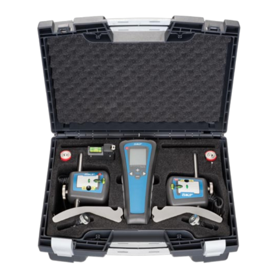
TKSA 20 Measuring Unit (Annex 2)
TKSA 20 Display Unit
Movable / Stationary
(Annex 1)
/mils
mm
A
S
B
F 1
M
C
F 2
1 Laser emission
1 Connector for MU on
Stationary machine
2 Laser warning signal
2 Connector for MU on
3 Laser detector
Movable machine
4 Vertical fine
adjustment
5 Spirit levels
Guideline for the maximum acceptable misalignment (Annex 3)
rpm
mm/100 mm
mm
0 - 1000
0.10
0.13
1000 - 2000
0.08
0.10
2000 - 3000
0.07
0.07
3000 - 4000
0.06
0.05
4000 - 6000
0.05
0.03
Measurement unit setting
The tool is delivered with a pre-selection for measurements in
millimeters (metric).
To change into inches (imperial), press the "-" key while switching
on the unit.
To revert back to millimeters, press the "+" key while switching on
the unit.
SKF TKSA 20
Safety recommendations
• Always turn off the power of the
drive machine before you start
working.
• Do not expose the equipment to
rough handling or heavy impacts.
• Always read and follow the operating instructions.
• The tool uses two laser diodes with an output power below
1 mW (class 2). Still, never stare directly into the laser
transmitter.
• Calibrate the equipment regularly.
• Never aim the laser line into someone's eyes.
• Opening the housing of the measuring unit may result in
hazardous light exposure and voids warranty.
• The equipment should not be used in areas where there is a
risk for explosion.
• Do not expose the equipment to high humidity or direct
contact with water.
• All repair work should be taken care of by an SKF repair shop.
6 Release / Tightening
knob
7 Connection rod
8 Chain fixation screw
9 Locking chain
We, SKF Maintenance Products, Kelvinbaan 16,
10 M echanical fixture
3439 MT Nieuwegein, The Netherlands, declare that the
has been designed and manufactured in accordance with
EMC DIRECTIVE 2004/108/EC as outlined in the harmonized norm for
Emission: EN 61000-6-3:2007
Immunity: EN 61000-6-2:2005, EN 61000-4-2, -3
0.001"/1"
0.001"
1.0
5.1
Directive RoHS, 2002/95/EC
0.8
3.9
0.7
2.8
The laser is classified in accordance with the EN 60825-1:2007.
0.6
2.0
The laser complies with 21 CFR 1040.10 and 1040.11 except for
0.5
1.2
deviations pursuant to Laser Notice No. 50, dated June 24, 2007
The Netherlands, March 2010
Sebastien David
Manager Product Development and Quality
The contents of this publication are the copyright of the publisher and may not be reproduced
(even extracts) unless prior written permission is granted. Every care has been taken to ensure the
accuracy of the information contained in this publication but no liability can be accepted for any loss
or damage whether direct, indirect or consequential arising out of use of the information contained
herein.
SKF Maintenance Products
Publication MP5370E · 2010/03 · © SKF 2010
® SKF is a registered trademark of the SKF Group
5
EC Declaration of conformity
SKF Shaft Alignment Tool TKSA 20
www.mapro.skf.com
www.skf.com/mount
SKF Shaft Alignment Tool
TKSA 20
Table des Matières

Manuels Connexes pour SKF TKSA 20


Sommaire des Matières pour SKF TKSA 20
-
Page 3: Guide De Défaut D'alignement Maximum Admissible
Recommandations de sécurité Appareil de mesure TKSA 20 (Annexe 2) Unité de visualisation • Toujours couper l’alimentation de la Mobile / Fixe TKSA 20 (Annexe 1) machine motrice avant de vous mettre à l’oeuvre. • Evitez de manipuler brutalement ou de faire tomber l’équipement. • Lire et respecter toujours les instructions d’utilisation. /mils • L’appareil contient deux diodes laser d’une puissance de sortie inférieure à 1mW. Cependant, il ne faut jamais regarder directement l’émetteur laser. SKF Shaft Alignment Tool TKSA 20 • Etalonner régulièrement l’équipement. - Page 4 Position des appareils de mesure des opérations 1 à 3, positionnez les appareils de mesure à 12h00. Appuyez Résultat vertical / ajustement Résultat horizontal / ajustement simultanément sur les boutons + et - 12h00 3h00 Affichage de pied mou pour obtenir le mode pied mou. Appuyez sur le bouton « Suivant » pour remettre à zéro les valeurs de pied mou affichées. Pour contrôler un pied mou, desserrez le boulon du pied. Suivez la valeur F1 pour un pied avant et la valeur F2 pour un pied arrière. Notez cette valeur. a) Mesurez les distances A, B et C de l’application. Si la valeur est inférieure à 0,05 mm (2 mils), le support est correct. Serrez à nouveau le boulon et contrôlez un autre pied. b) Ajustez chaque valeur affichée à l’écran avec les boutons + et -. Si la valeur est supérieure à 0,05 mm (2 mils), ce pied peut être le pied mou. Serrez à nouveau le boulon et contrôlez le pied diamétralement opposé. Le pied mou est celui présentant la c) Confirmez la saisie de chaque valeur en appuyant sur déviation la plus importante. Une fois tous les pieds contrôlés, corrigez le pied mou, le cas échéant. SKF TKSA 20 SKF TKSA 20 SKF TKSA 20...