Table des Matières
Publicité
Les langues disponibles
Les langues disponibles
Liens rapides
Publicité
Chapitres
Table des Matières
Dépannage

Manuels Connexes pour Beta 1760DGT/2


Sommaire des Matières pour Beta 1760DGT/2
- Page 1 1760DGT/2 Multimetro digitale con oscilloscopio Manuale d’uso...
-
Page 2: Table Des Matières
Contenuto Dichiarazione sul copyright / Dichiarazione di conformità UE……………….….3 Riassunto generale sulla sicurezza………………………………………………..4 Termini e simboli di sicurezza……………………………………………………..5 Rottamazione del prodotto………………………………………………………….5 Breve introduzione…………………………………………………………………..6 Guida introduttiva……………………………………………………………………7 Ispezione generale…………………………………………………………….…….8 Uso della serratura di sicurezza……………………………………………………8 Regolare la staffa…………………………………………………………………….9 Pannello frontale…………………………………………………………………...10 L'interfaccia utente…………………………………………………………………11 Controllo funzionale………………………………………………………………..11 Verifica della sonda……………..………………………………………………….12 Introduzione alle funzioni……..…………………………………………………...14 Menu e tasti di controllo…………………………………………………………...15... -
Page 3: Dichiarazione Sul Copyright / Dichiarazione Di Conformità Ue
Dichiarazione sul copyright Tutti i diritti riservati; nessuna parte di questo documento può essere riprodotta o trasmessa in qualsiasi forma o con qualsiasi mezzo, elettronico o meccanico, senza previa autorizzazione scritta del produttore. Il produttore si riserva tutti i diritti di modificare questo documento senza preavviso. -
Page 4: Riassunto Generale Sulla Sicurezza
Riassunto generale sulla sicurezza Leggere le seguenti precauzioni di sicurezza per evitare lesioni e prevenire danni al prodotto o ai prodotti ad esso collegati. Per eludere i potenziali pericoli, utilizzare questo prodotto solo come specificato. Solo personale qualificato dovrebbe eseguire la manutenzione. Evitare incendi o lesioni personali. -
Page 5: Termini E Simboli Di Sicurezza
Termini e simboli di sicurezza Termini sul prodotto. I seguenti termini possono apparire sul prodotto: Pericolo Rappresenta che i danni possono essere causati all’utente se si esegue l'operazione. Avviso Rappresenta che i danni latenti possono essere causati all'utente se si esegue l'operazione. Avviso Rappresenta il danno eventualmente causato al prodotto o ad altre proprietà... -
Page 6: Breve Introduzione
Breve introduzione Questo oscilloscopio è compatto e portatile; il display TFT LCD a colori con il menu a comparsa migliora notevolmente la produttività dell'utente. Questo strumento è potente con prestazioni superiori ed è economico. La frequenza di campionamento in tempo reale può arrivare a 250MSa / S, può... -
Page 7: Guida Introduttiva
Guida introduttiva Questo oscilloscopio è uno strumento portatile piccolo e leggero, ha un pannello frontale pratico e facile da usare, è possibile eseguire test di base. Ispezione generale Uso della serratura di sicurezza Regolare la staffa Pannello frontale ... -
Page 8: Ispezione Generale
Ispezione generale Si prega di controllare lo strumento come segue dopo averlo ricevuto; Controllare se il contenitore di spedizione presenta danni; Conservare il contenitore di spedizione danneggiato o il materiale di imbottitura finché il contenuto della spedizione non è stato controllato per verificarne la completezza e la funzionalità... -
Page 9: Regolare La Staffa
Regolare la staffa Quando si utilizza lo strumento, l'utente può aprire la staffa di supporto per inclinare lo strumento verso l'alto per facilitare l'operazione e l'osservazione. Quando lo strumento non è in uso, l'utente può chiudere la staffa di supporto per riporre lo strumento o tenerlo in posizione orizzontale su un piano. -
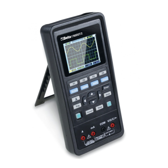
Page 10: Pannello Frontale
Pannello frontale Lo schema seguente descrive brevemente il pannello anteriore di questo oscilloscopio in modo che possiate comprenderlo nel più breve tempo possibile. -
Page 11: L'interfaccia Utente
L’interfaccia utente Controllo funzionale Seguire i seguenti passaggi per eseguire un rapido controllo funzionale del proprio oscilloscopio. 1. Potenza Premere il tasto di accensione e il dispositivo si accende. Premere di nuovo il tasto di accensione e il dispositivo si spegnerà. Prima di accenderlo, si prega di controllare che la batteria abbia abbastanza potenza. -
Page 12: Verifica Della Sonda
2. Osservare la forma d'onda 1) Impostare l'interruttore sulla sonda su 1X e collegare la sonda al Canale 1 dell'oscilloscopio. Innanzitutto, allineare la fessura nel connettore della sonda con la protuberanza sul CH1 BNC e premere per connettersi; quindi, girare a destra per bloccare la sonda in posizione;... - Page 13 segnale di uscita come onda quadra 2V @ 1KHz; Il terminale Gen Out dell'oscilloscopio senza funzione di generatore di segnale emette automaticamente un'onda quadra da 2 V a 1 KHz. Premere il pulsante [Auto]. 2. Controllare la forma della forma d'onda visualizzata. Compensated correctly Overcompensated Undercompensated...
-
Page 14: Introduzione Alle Funzioni
Introduzione alle funzioni Questo capitolo introdurrà in dettaglio le funzioni dell'oscilloscopio. Menu e tasti di controllo Connettori Impostato automaticamente Impostazione predefinita Sistema orizzontale Sistema verticale Sistema di trigger Salva forma d'onda Forma d'onda di riferimento ... -
Page 15: Menu E Tasti Di Controllo
Menu e tasti di controllo Scope: modalità oscilloscopio. DMM: modalità multimetro. AWG: generatore di forme d'onda. Menu: menu delle funzioni. Trig: menu di impostazione Trigger. Enter: salvare le impostazioni definite dall'utente dell'oscilloscopio; Nel generatore, premere il pulsante per confermare dopo aver inserito il carattere. Auto: regola automaticamente le scale orizzontale e verticale dell'oscilloscopio automaticamente e imposta l'accoppiamento del trigger, il tipo, la posizione, la pendenza, il livello e la modalità, ecc., Per acquisire una visualizzazione della forma d'onda stabile. -
Page 16: Connettori
Nel generatore, dopo aver scelto un parametro, il tasto di direzione sinistro e inferiore ridurrà il valore del parametro, il tasto di direzione destra e alto aumenterà il valore del parametro; è anche usato per la selezione digitale della tastiera virtuale. F1/F2/F3/F4 Il tasto multifunzione, in ciascuna modalità... -
Page 17: Imposta Automaticamente
Imposta automaticamente Il set automatico è uno dei vantaggi che hanno gli oscilloscopi digitali. Quando si preme il pulsante Auto, l'oscilloscopio identificherà il tipo di forma d'onda (onda sinusoidale o quadra) e regolerà i controlli in base ai segnali di ingresso in modo che possa visualizzare accuratamente la forma d'onda del segnale di ingresso. -
Page 18: Sistema Orizzontale
Menu o Opzione, Pulsante Settaggio Sistema o Manopola di Default Tipo Sorgente Cursore Orizzontale ±4div (ampiezza) Verticale (tempo) ±4div Display Formato Posizione 0.00s Orizzontale SEC/DIV 500μs Misurazione On o Off Sorgente Pendenza Crescente Trigger (Edge) Modo Auto Livello 0.00v Limite larg.di banda Illimitato Accoppiamento Verticale... -
Page 19: Sistema Verticale
2. Manopola di posizione orizzontale: utilizzata per controllare la posizione del trigger rispetto al centro dello schermo. Premere il pulsante Time e i pulsanti Destra o Sinistra per spostare la forma d'onda a destra o a sinistra. La risoluzione chiave varia in base alla base dei tempi. -
Page 20: Sistema Trigger
3. Menu impostazione canale Opzione Settaggio Commento Attiva la visualizzazione della forma d’onda. On/Off Disattiva la visualizzazione della forma d’onda. La corrente continua trasmette sia le componenti CC che quelle CA del segnale di ingresso. AC blocca la componente DC del segnale di Coupling ingresso e attenua i segnali inferiori a 10Hz. -
Page 21: Salvare La Forma D'onda
Premere il pulsante Trig per accedere al menu trigger. Sorgente trigger: selezionare il segnale sorgente trigger su CH1 o CH2. È possibile utilizzare le opzioni della sorgente di trigger per selezionare il segnale che l'oscilloscopio utilizza come trigger. Pendenza: selezionare la pendenza del trigger per salire, scendere, salire e scendere. Trigger Mode: è... -
Page 22: Forma D'onda Di Riferimento
Per salvare la forma d’onda attenersi alla seguente procedura: 1. Premere F1 per selezionare la posizione di archiviazione delle forme d’onda. 2. Premere F2 per salvare i dati della forma d’onda nella posizione specificata. Premendo a lungo il pulsante per accedere e selezionare F4->F2 (salvataggio dati) come scelta rapida. -
Page 23: Misurazione
Misurazione Misurazione della scala Reticolo: questo metodo consente di effettuare una stima rapida e visiva e di effettuare una semplice misurazione attraverso le divisioni del reticolo e il fattore di scala. Ad esempio, è possibile effettuare misurazioni semplici contando le divisioni di reticolo maggiore e minore coinvolte e moltiplicando per il fattore di scala. -
Page 24: Utilità
4. Premere F4 per accedere alla seconda pagina, premere F1 o F2 per selezionare Cursore1 o Cursore2, premere su, giù, sinistra e destra per spostare Cursore1 o Cursore1; 5. Il risultato della misurazione del cursore verrà visualizzato nel menu del cursore. Misura automatica L'oscilloscopio fornisce 2 tipi di misurazioni automatiche, tra cui frequenza e ampiezza. - Page 25 5 Minuti 10 Minuti Spegnimento Imposta il tempo di spegnimento 20 Minuti automatico automatico. 30 Minuti Illimitato Start Avvia l'autocalibrazione. Calibrazione Return Esci dall'auto-calibrazione. Nota: 1. Il tempo di retroilluminazione e il tempo di spegnimento automatico non verranno eseguiti quando l'oscilloscopio viene collegato a un dispositivo di ricarica esterno o collegato a un computer tramite un cavo USB.
- Page 26 Premere il pulsante una volta e fai clic su F1 per confermare per richiamare le impostazioni personalizzate. Salvare I dati: premere a lungo il pulsante per accedere, e selezionare F4->F1 (Data Save) come tasti di scelta rapida. Premere Menu -> Save per accedere al menu Salva, selezionare la posizione, premere il pulsante una volta per salvare i dati della forma d'onda corrente.
-
Page 27: Dmm
Questo capitolo introduce la funzione multimetro. Interfaccia I tipi di misurazione includono tensione continua (V, mV), tensione AC, corrente continua (A, mA), corrente AC (A, mA), resistenza, capacità, diodo e test on-off. Misurazione 1. Misura della tensione DC e AC. a) Premere il pulsante di accensione per accendere, quindi premere il pulsante "DMM"... - Page 28 2. Misura della corrente DC e AC a) Premere il pulsante di accensione per accendere, quindi premere il pulsante "DMM" per accedere all'interfaccia della funzione multimetro; b) Per misurare la corrente DC superiore a 200 mA, premere su, giù, sinistra e destra tasti o tasti multifunzione F1, F2, F3, F4 per selezionare "DC A"...
- Page 29 c) Inserire la spina del puntale nero nell’ingresso della presa a banana COM e inserire la spina del puntale rosso nell’ingresso della presa a banana V / Ω / C; d) Collegare i puntali rosso e nero al punto da misurare. Il valore del diodo verrà visualizzato sullo schermo.
-
Page 30: Generatore
Generatore Questo capitolo introduce la funzione del generatore di forme d’onda. Interfaccia Descrizione operazioni Premere il pulsante di accensione per accendere, quindi premere il pulsante "AWG" per accedere all'interfaccia della funzione del generatore di forme d'onda. 1. Imposta tipo Premere il tasto F1 per selezionare la forma d'onda del segnale desiderata, il tipo di forma d'onda opzionale include quadra, triangolare, seno, trapezoidale e quattro arbitrari. - Page 31 per impostare il parametro di frequenza, selezionare "OK" e premere il pulsante "Enter" per confermare. 3. Impostare l'ampiezza Premere il tasto F3 per selezionare Amplitude, quindi utilizzare la i tasti di direzione su, giù, sinistra e destra per regolare la frequenza, premere il tasto F3 per aprire nuovamente la tastiera digitale, utilizzare i tasti su, giù, sinistra, destra e "Enter"...
-
Page 32: Emettere La Forma D'onda Sinusoidale
Emettere la forma d’onda sinusoidale Emettere una forma d'onda sinusoidale con 10KHz / 2.5Vpp come segue: 1. Premere il pulsante AWG per accedere all'interfaccia della funzione del generatore di forme d'onda. 2. Premere F1 per selezionare "Sine"; 3. Frequenza: prima premere il tasto F2 per selezionare Frequency, quindi utilizzare i tasti su, giù, sinistra e destra per regolare la frequenza. -
Page 33: Emettere La Forma D'onda Arbitraria
7. La forma d'onda osservata da un oscilloscopio è la seguente: Emettere la forma d’onda arbitraria 1. Installare il software. Scarica il software più recente sul sito Web ufficiale, fai doppio clic su Setup.exe per l'installazione. 2. Installare il driver Collegare l'oscilloscopio al computer tramite il cavo USB. - Page 34 6. Seleziona "Arb Channel" come Arb1 / Arb2 / Arb3 / Arb4. Ogni canale arb può salvare solo una forma d'onda arbitraria che è stata scaricata l'ultima volta. Riaccendere dopo lo spegnimento e richiamare automaticamente. 7. Disegnare le onde arbitrarie nell'area della forma d'onda con il mouse. 8.
-
Page 35: Carica
Carica Quando la cornice della batteria sullo schermo viene visualizzata come vuota, indica che la batteria sta per esaurirsi. Quando la carica della batteria è troppo bassa, l'oscilloscopio richiederà "Spegni dopo 5 secondi". Per evitare lo spegnimento automatico dell'oscilloscopio a causa di un'alimentazione insufficiente, caricarlo per tempo. Se si preme il pulsante di alimentazione, l'oscilloscopio non reagirà, indicando che la batteria potrebbe essere scarica. - Page 36 Aprire la staffa di supporto, ci sono due viti. Rimuovere le viti e rimuovere il coperchio della batteria, vedrete le batterie. Ora è possibile rimuovere le batterie e sostituirle. Attenzione: prestare attenzione ai poli positivo e negativo delle batterie quando si sostituiscono le batterie.
-
Page 37: Risoluzione Dei Problemi
Risoluzione dei problemi 1. Se l'oscilloscopio non si avvia all'accensione, attenersi alla seguente procedura: 1) Controllare se la batteria è installata e controllare se il livello della batteria è sufficiente. 2) Se il livello della batteria non è sufficiente, utilizzare l'alimentatore per caricare. 3) Riavviare lo strumento dopo che il livello della batteria è... -
Page 38: Cura Generale E Pulizia
Cura generale e pulizia Cura generale Non mettere o lasciare il dispositivo in un luogo in cui il display LCD sarà esposto alla luce solare diretta per lunghi periodi di tempo. Nota: per evitare danni all'oscilloscopio o alle sonde, non utilizzare spray, liquidi o solventi. - Page 39 Specifiche Oscilloscopio Orizzontale Larghezza di banda 40MHz ≤8.75ns Tempo di salita Intervallo di frequenza di 250MSa/s (singolo canale), 125MSa/s (doppio canale) campionamento Interpolazione delle forme (sin x)/x d’onda Max. Campioni 6K per canale singolo, Campioni 3K per Lunghezza record doppio canale Gamma SEC/DIV 5ns/div~500s/div 1, 2, 5 sequenza Verticale...
- Page 40 Ingresso Accoppiamento DC, AC o GND Inpedenza di ingresso 25pF±3 pF,1MΩ±2% DC accoppiata Attenuazione sonda 1X, 10X Fattori di attenuazione 1X, 10X, 100X, 1000X della sonda supportati Tensione di protezione 150V ingresso Misurazione Differenza di tensione tra I cursori: △V Cursori Differenza di tempo tra I cursori: △T Misurazioni automatiche...
- Page 41 Generatore di forme d’onda arbitrarie Sine: 1Hz~25MHz Square: 1Hz~10MHz Frequenza forma d’onda Ramp: 1Hz~1MHz EXP: 1Hz~5MHz Campionatura 250MSa/s 2.5Vpp (50Ω) Ampiezza 5Vpp (alta impedenza) Risoluzione frequenza 0.10% 1CH uscita della forma d’onda Canale Profondità forma d’onda 512Sa Risoluzione verticale 12 bit 50 Ω...
- Page 42 200.0mA 100uA ±(1.5% + 2) 4.000A ±(1.8% + 2) 10.00A ±(3% + 2) 10mA Protezione da sovraccarico: Fusibile auto ripristinante: 200mA/250V, 4A e 10A gamma senza fusibile. 40.00mA 10uA ±(1.3% + 2) 400.0mA ±(1.8% + 2) 100uA 4.000A ±(2% + 3) Corrente AC 10.00A 10mA...
-
Page 43: Appendice B: Accessori
Appendice B: Accessori Accessori standard • Sonda passiva (1,5 m), 1: 1 (10: 1) • Adattatore di alimentazione • Cavo USB • Cavetti BNC / Pinze a coccodrillo • Puntali multimetro • CD con software • Guida rapida • Riassunto generale sulla sicurezza... - Page 44 1760DGT/2 Digital multimeter with oscilloscope User Manual...
- Page 45 Content Copyright declaration / EU declaration of conformity…………………………..46 General Safety Summary…………………………………………………………47 Safety Terms and Symbols……………………………………………………….48 Product Scrapping…………………………………………………………………48 Brief Introduction…………………………………………………………………...49 Getting Started……………………………………………………………………...50 General Inspection…………………………………………………………………51 Use of safety keyhole………………………………………………………………51 Adjust the bracket…………………………………………………………………..52 Front Panel………………………………………………………………………….53 The user interface………………………………………………………………….54 Functional Check…………………………………………………………………..54 Probe Check………………………………………………………………………..55 Function Introduction………………………………………………………………57 Menu and Control Keys……………………………………………………………58 Connectors………………………………………………………………………….59 Automatically set……………………………………………………………………60...
-
Page 46: Copyright Declaration / Eu Declaration Of Conformity
Copyright Declaration All rights reserved; no part of this document may be reproduced or transmitted in any form or by any means, electronic or mechanical, without prior written permission from manufacturer. The manufacturer reserves all rights to modify this document without prior notice. Please contact manufacturer for the latest version of this document before placing an order. -
Page 47: General Safety Summary
General Safety Summary Read the following safety precautions to avoid injury and prevent damage to this product or any products connected to it. To evade potential hazards, use this product only as specified. Only qualified personnel should perform maintenance. Avoid fire or personal injury. Use suitable power cord. -
Page 48: Safety Terms And Symbols
Safety Terms and Symbols Terms on the product. The following terms may appear on the product: Danger It represents that harms may be caused to you at once if you perform the operation. Warning It represents that latent harms may be caused to you if you perform the operation. -
Page 49: Brief Introduction
Brief Introduction This series oscilloscope is compact, portable, and flexible operation; Using color TFTLCD and pop-up menus to display; to achieve its ease of use, greatly improving the user productivity. In addition, this product has superior performance and it is powerful, affordable, high cost. The real-time sampling rate can be as high as 250MSa/S,can meet the market demand of complex signals and capture speed;... -
Page 50: Getting Started
Getting Started This oscilloscope is a small, lightweight portable instrument,to provide users with a convenient and easy to operate front panel, you can perform basic tests. General Inspection Use of safety keyhole Adjust the bracket Front Panel ... -
Page 51: General Inspection
General Inspection Please check the instrument as following steps after receiving an oscilloscope: Check the shipping container for damage: Keep the damaged shipping container or cushioning material until the contents of the shipment have been checked for completeness and the instrument has been checked mechanically and electrically. -
Page 52: Adjust The Bracket
Adjust the bracket When using the instrument, the user can open the support foot as a support to tilt the instrument upward for easy operation and observation. When the instrument is not in use, the user can close the support foot to facilitate placement or handling. After adjusting the rack, the instrument can be suspended on the vertical plane. -
Page 53: Front Panel
Front Panel The following diagram briefly describes the front panel of this series oscilloscope, so that you can be familiar with it in the shortest possible time. -
Page 54: The User Interface
The user interface Functional Check Follow the steps below to perform a quick functional check to your oscilloscope. 1. Power Press the power key and the device starts. Press the power key again, and the device will shut down. Before start it, please confirm that the battery has enough power. -
Page 55: Probe Check
should be inserted into the Gen Out output terminal, and the probe grounding clamp should be clamped on the metal outer ring of the Gen Out output terminal. Recommended input ~2V@1KHz peak-peak square wave. 3) Press the [Auto] button and you should see within a few seconds a square wave of about 2V peak-to-peak at 1KHz in the display. - Page 56 3. If necessary, use a nonmetallic screwdriver to adjust the variable capacity of your probe until the shape of the waveform turns to be the same as the above figure. Repeat this step as necessary. See the figure below for the way of adjustment. Probe Attenuation Setting Probes are of various attenuation factors which affect the vertical scale of the signal.
-
Page 57: Function Introduction
Function Introduction This chapter will introduce the functions of oscilloscope in detail. Menu and Control Keys Connectors Automatically set Default setting Horizontal System Vertical System Trigger System Save Waveform Reference Waveform ... -
Page 58: Menu And Control Keys
Menu and Control Keys All the keys are described as follows: Scope: Oscilloscope mode. DMM:Multimeter mode. AWG:Waveform generator. Menu:Function menu. Trig:Trigger setting menu. Enter: In scope, save the user-defined settings of the oscilloscope; In generator, press the button to confirm after entering the character. Auto: It automatically adjust the horizontal and vertical scales of the oscilloscope automatically and set the trigger coupling, type, position, slope, level and mode, etc., to acquire a stable waveform display. -
Page 59: Connectors
F1/F2/F3/F4: Multi function key, in each menu mode, is responsible for selecting corresponding menu items in the screen. Shortcut keys. Long press this button to enter the menu, and choose shortcut key function; After setting, press this button single time to respond to the corresponding function. -
Page 60: Automatically Set
Automatically set Auto set is one of the advantages digital oscilloscopes have. When you push the Auto button, the oscilloscope will identify the type of waveform (sine or square wave) and adjust controls according to input signals so that it can accurately display the waveform of the input signal. -
Page 61: Horizontal System
(amplitude) Vertical (time) ±4div Display Format Position 0.00s Horizontal SEC/DIV 500μs Measure On or Off Source Slope Rising Trigger (Edge) Mode Auto Level 0.00v Bandwidth Limit Unlimited Coupling Vertical System, Probe Attenuation All Channels Position 0.00div (0.00V) VOLTS/DIV The following settings do not change when you recall default settings. ... -
Page 62: Vertical System
X-Y: The XY mode is used to analyze phase differences, such as those represented by Lissajous patterns. The format plots the voltage on CH1 against the voltage on CH2, where CH1 is the horizontal axis and CH2 is the vertical axis. You may view the same waveform in XY mode. -
Page 63: Trigger System
Limits the bandwidth to reduce display noise; filters the signal to eliminate noise and other unnecessary Limit HF components. The invert function turns the displayed waveform 180 degrees, with respect to the ground level. When the Invert oscilloscope is triggered on the inverted signal, the trigger is also inverted. -
Page 64: Save Waveform
Save Waveform Press Menu button to enter, and select Save to enter store waveform menu. The waveform can be saved to the oscilloscope inside, also can be recalled to view. The Save Menu Table Menu Setting Description Position 1,2,3,4,5,6 Select the internal storage position. Save Save waveform data. -
Page 65: Measurement
3. Press F3 to select the source to CH1 (or CH2), and only select the open channel. 4. Press F4 to save the current waveform to the specified location.. Measurement Scale measurement Graticule: This method allows you to make a quick, visual estimate and take a simple measurement through the graticule divisions and the scale factor. -
Page 66: Utility
2. Press F2 to select a type of cursor measurement. 3. Press F3 to select the channel that needs to be measured. 4. Press F4 to enter the second page, press F1 or F2 to select Cursor1 or Cursor2, press up, down, left and right to move Cursor1 or Cursor1; 5. - Page 67 System Display system information, such as software information version or PCB version. 5 Minute 10Minute Automatic 20Minute Set automatic shutdown time. shutdown 30Minute Unlimited Start Start the self calibration. Calibration Return Exit the self calibration. Note: 1. Backlight time and automatic shutdown time will not be executed when the oscilloscope is plugged in with an external charging device or connected to a computer via a USB cable.
-
Page 68: Dmm
This chapter introduces the multimeter function. Interface The measuring types include DC voltage (V, mV), AC voltage, DC current (A, mA), AC current (A, mA), resistance, capacitance, diode, and on-off test. Measurement 1. DC and AC voltage measurement a) Press the power button to turn on, then press the "DMM" button to enter to the multimeter function interface;... - Page 69 2. DC and AC current measurement a) Press the power button to turn on, then press the "DMM" button to enter to the multimeter function interface; b) To measure the DC current greater than 200mA, press the up, down, left and right keys or F1, F2, F3, F4 multi function keys to select "DC A"...
- Page 70 6. Buzzer measurement a) Press the power button to turn on, then press the "DMM" button to enter to the multimeter function interface; b) Press the up, down, left and right direction keys or F1, F2, F3, F4 multi-function keys to select "Buzzer";...
-
Page 71: Generator
Generator This chapter introduces the function of waveform generator. Interface Operation description Press the power button to turn on, and then press the "AWG" button to enter the waveform generator function interface. 1. Set type Press F1 button to select the desired signal waveform, the optional waveform type includes square, triangle, sine, trapezoidal and four arbitrary. -
Page 72: Output The Sine Waveform
the up, down, left, right direction keys and "Enter" key to set frequency parameter, select "OK" and press "Enter" button to confirm. 4. Set offset Press F4 button to enter the second page. Press F2 to select Offset, then use the up, down, left and right direction keys to adjust the frequency, press F2 button to open the digital keyboard again, use the up, down, left, right direction keys and "Enter"... - Page 73 keys and "Enter" key to set offset parameter, select "OK" and press "Enter" button to confirm. 6. Press button, the backlight of the button turns green, i.e. output sine waveform. 7. The waveform observed by an oscilloscope is as follows:...
-
Page 74: Output The Arb Waveform
Output the arb waveform 1. Install the software Download the latest software on the official website, double click Setup.exe to install. 2. Install the driver Connect the oscilloscope to the computer through the USB cable. Open the device manager of the computer and find the device. If the device icon is shown in the following picture, you need to install the driver manually. - Page 75 8. Connect Gen Out connector to oscilloscope for observation.
-
Page 76: Charge
Charge When the battery frame on the screen is displayed as blank, it indicates that the battery is about to run out. When the battery power is too low, the oscilloscope will prompt “Power off after 5s”. In order to avoid the automatic shutdown of the oscilloscope due to insufficient power supply, please charge it in time. - Page 77 Unfold the supporting leg, there are two screws. Remove the screws and remove the battery cover, you will see the batteries. Now you can remove the battery and replace. Attention: Pay attention to the positive and negative poles of batteries when replacing batteries.
-
Page 78: Troubleshooting
Troubleshooting 1. If the oscilloscope does not start up at power on, follow these steps: 1) Check whether the battery is installed and confirm whether the battery level is enough. 2) If the battery level is not enough, use the power adapter to charge. 3)... -
Page 79: General Care And Cleaning
General Care and Cleaning General Care Do not put or leave the device in a place where the LCD display will be exposed to direct sunlight for long periods of time. Note: To avoid damage to the oscilloscope or probes, do not expose them to sprays, liquids, or solvents. -
Page 80: Appendix A: Technical Specifications
Appendix A: Technical Specifications All specifications herein mentioned apply to the series oscilloscopes. Before checking an oscilloscope to see if it complies with these specifications, make sure it meets the following conditions: The oscilloscope must have been operating continuously for twenty minutes under the specified operating temperature. - Page 81 Trigger Type Edge Mode Auto, Normal, single Level ±4 divisions from center of screen Trigger Level Accuracy 0.2div × volts/div within ±4 divisions from center of screen Slope Rising, Falling, Rising & Falling Source CH1, CH2 Input Coupling DC, AC or GND Input Impedance, 25pF±3 pF,1MΩ±2% DC coupled...
- Page 82 minutes on each axis Mechanical Shock Operating 50g, 11ms, half sine Mechanical Dimension 199 x 98x 40mm (L x W x H) Weight 624g Arbitrary Waveform Generator Sine: 1Hz~25MHz Square: 1Hz~10MHz Waveform Frequency Ramp: 1Hz~1MHz EXP: 1Hz~5MHz Sampling 250MSa/s 2.5Vpp(50Ω) Amplitude 5Vpp(High impedance) Frequency Resolution...
- Page 83 4.000V 40.00V ±(1.2% + 5) 10mV 400.0V 100mV AC Voltage 600.0V ±(1.5% + 5) Frequency: 40Hz~400Hz; Frequency of 400V and 600V: 40Hz~100Hz 40.00mA 10uA ±(1% + 2) 200.0mA ±(1.5% + 2) 100uA 4.000A ±(1.8% + 2) DC Current 10.00A 10mA ±(3% + 2)...
-
Page 84: Appendix B: Accessories
Appendix B: Accessories Standard accessories • Passive probe (1.5 m), 1: 1 (10: 1) • Power adapter • USB cable • BNC cables / Alligator clips • Multimeter test leads • CD with software • Quick guide • General summary on safety... - Page 85 1760DGT/2 Multimètre numérique avec oscilloscope Manuel de l'Utilisateur...
- Page 86 Contenu Déclaration de copyright / Déclaration de conformitè UE……………….……87 Résumé général de sécurité…………..…………………………………………88 ……….89 …………………………………………… Termes et symboles de sécurité ………………….…………………………………………… Mise au rebut du produit Courte Introduction………………………………………………………………...90 Commencer………………………………………………………………………...91 Inspection générale ………………………………………….……………………92 Utilisation d'un trou de serrure de sécurité …………………..…………………92 Ajustez le support………………………………………………………………….93 Panneau avant….………………………………………………………………….94 L'interface utilisateur………………………………………………………………95...
-
Page 87: Déclaration De Copyright / Déclaration De Conformitè Ue
Déclaration de copyright Tous les droits sont réservés; aucune partie de ce document ne peut être reproduite ou transmise sous quelque forme ou par quelque moyen que ce soit, électronique ou mécanique, sans l'autorisation écrite préalable du fabricant. Le fabricant se réserve tous les droits de modifier ce document sans préavis. Veuillez contacter le fabricant pour la dernière version de ce document avant de passer une commande. -
Page 88: Résumé Général De Sécurité
Résumé général de sécurité Lisez les précautions de sécurité suivantes pour éviter les blessures et éviter d'endommager ce produit ou tout produit qui y est connecté. Pour éviter les dangers potentiels, utilisez ce produit uniquement comme spécifié. Seul un personnel qualifié doit effectuer la maintenance. Évitez le feu ou les blessures. -
Page 89: Termes Et Symboles De Sécurité
Termes et symboles de sécurité Conditions sur le produit. Les termes suivants peuvent apparaître sur le produit: Danger Cela signifie que des dommages peuvent vous être causés immédiatement si vous effectuez l'opération. Avertissement Cela signifie que des dommages latents peuvent vous être causés si vous effectuez l'opération. -
Page 90: Courte Introduction
Courte introduction Cet oscilloscope de série est un fonctionnement compact, portable et flexible; Utilisation de TFTLCD couleur et de menus contextuels pour afficher; pour atteindre sa facilité d'utilisation, améliorant considérablement la productivité de l'utilisateur. De plus, ce produit a des performances supérieures et il est puissant, abordable et d'un coût élevé. -
Page 91: Commencer
Commencer Cet oscilloscope est un petit instrument portable léger , pour fournir aux utilisateurs un panneau avant pratique et facile à utiliser, vous pouvez effectuer des tests de base. Inspection générale Utilisation du trou de serrure de sécurité ... -
Page 92: Inspection Générale
Inspection générale Veuillez vérifier l'instrument comme suit après avoir reçu un oscilloscope: Vérifiez que le conteneur d'expédition n'est pas endommagé: Conservez le conteneur d'expédition ou le matériau de rembourrage endommagé jusqu'à ce que le contenu de l'envoi ait été vérifié pour être complet et que l'instrument ait été vérifié... -
Page 93: Ajustez Le Support
Ajustez le support Lors de l'utilisation de l'instrument, l'utilisateur peut ouvrir le pied de support comme support pour incliner l'instrument vers le haut pour une utilisation et une observation faciles. Lorsque l'instrument n'est pas utilisé, l'utilisateur peut fermer le pied de support pour faciliter le placement ou la manipulation. -
Page 94: Panneau Avant
Panneau avant Le schéma suivant décrit brièvement le panneau avant de cet oscilloscope de série, afin que vous puissiez vous familiariser avec lui dans les plus brefs délais. -
Page 95: L'interface Utilisateur
L'interface utilisateur Contrôle fonctionnel Suivez les étapes ci-dessous pour effectuer une vérification fonctionnelle rapide de votre oscilloscope. 1. Puissance Appuyez sur la touche marche / arrêt et l'appareil démarre. Appuyez à nouveau sur la touche marche / arrêt et l'appareil s'éteindra. Avant de le démarrer, veuillez confirmer que la batterie est suffisamment chargée. -
Page 96: Vérification De La Sonde
verrouiller la sonde en place; 2) Si vous utilisez la pointe du crochet de la sonde, l'extrémité du crochet doit être retirée, la broche de la sonde doit être inséré dans la borne de sortie Gen Out, et la pince de mise à... - Page 97 3. Si nécessaire, utilisez un tournevis non métallique pour régler la capacité variable de votre sonde jusqu'à ce que la forme de la forme d'onde devienne la même que la figure ci- dessus. Répétez cette étape si nécessaire. Voir la figure ci-dessous pour le mode de réglage.
-
Page 98: Introduction Aux Fonctions
Introduction aux fonctions Ce chapitre présentera en détail les fonctions de l'oscilloscope. Menu et touches de commande Connecteurs Défini automatiquement Réglage par défaut Système horizontal Système vertical Système de déclenchement Enregistrer la forme d'onde ... -
Page 99: Menu Et Touches De Commande
Menu et touches de commande Toutes les clés sont décrites comme suit: Scope: mode Oscilloscope. DMM: Mode multimètre. AWG: générateur de forme d'onde. Menu: menu de fonction. Trig: menu de réglage du déclencheur. Enter: Dans la portée, enregistrez les paramètres définis par l'utilisateur de l'oscilloscope; Dans le générateur, appuyez sur le bouton pour confirmer après avoir entré... -
Page 100: Connecteurs
augmentera la valeur du paramètre; il est également utilisé pour la sélection numérique du clavier virtuel. F1 / F2 / F3 / F4: La touche multifonction, dans chaque mode de menu, est chargée de sélectionner les éléments de menu correspondants à l'écran. : Raccourcis claviers. -
Page 101: Défini Automatiquement
Défini automatiquement Le réglage automatique est l'un des avantages des oscilloscopes numériques. Lorsque vous appuyez sur le bouton Auto, l'oscilloscope identifie le type de forme d'onde (onde sinusoïdale ou carrée) et ajuste les commandes en fonction des signaux d'entrée afin qu'il puisse afficher avec précision la forme d'onde du signal d'entrée. -
Page 102: Système Horizontal
Menu ou Option, bouton ou Paramètres système bouton par défaut Type La source Le curseur Horizontale ±4div (amplitude) Vertical (temps) ±4div Afficher Format Position 0.00s Horizontale SEC/DIV 500μs Mesure On or Off La source Déclencheur Pente En hausse (bord) Mode Auto Niveau 0.00v... -
Page 103: Système Vertical
2. Bouton de position horizontale: utilisé pour contrôler la position de déclenchement par rapport au centre de l'écran. Appuyez sur le bouton Heure et sur les boutons Droite ou Gauche pour déplacer la forme d'onde vers la droite ou la gauche. La résolution clé varie en fonction de la base de temps. -
Page 104: Système Trigger
3. Menu de réglage des canaux Les options Paramètres Commentaires Activez l'affichage de la forme d'onde. On/Off Désactivez l'affichage de la forme d'onde. DC passe les composants DC et AC du signal d'entrée. Couplage AC bloque la composante DC du signal d'entrée et atténue les signaux inférieurs à... -
Page 105: Enregistrer La Forme D'onde
déclencheur valide. Il permet la génération de formes d'onde non déclenchées avec une base de temps réglée à 100 ms / div ou plus lentement. Le mode normal met à jour les formes d'onde affichées uniquement lorsque l'oscilloscope détecte une condition de déclenchement valide. -
Page 106: Forme D'onde De Référence
Forme d'onde de référence Le canal REF est utilisé pour afficher la forme d'onde de référence, qui peut comparer les formes d'onde réelles avec les formes d'onde de référence afin de découvrir les différences. Appuyez sur le bouton Menu pour entrer et sélectionnez Ref pour accéder au menu de forme d'onde de référence. - Page 107 Mesure du curseur La mesure du curseur a deux lignes parallèles sur l'écran et déplacez deux lignes pour mesurer les paramètres de temps et de tension du signal d'entrée. Le résultat de la mesure du curseur sera affiché sur la deuxième page du menu du curseur. Avant d'utiliser la mesure par curseur, assurez-vous que la source mesurée est le signal que vous devez mesurer.
-
Page 108: Utilitaire
Mesure automatique L'oscilloscope fournit 2 types de mesures automatiques, y compris la fréquence et l'amplitude. Appuyez sur le bouton Menu pour entrer, sélectionnez Mesurer pour entrer la mesure automatique. Appuyez sur F1 pour ouvrir, les résultats de la mesure seront affichés dans le coin supérieur gauche de l'écran. - Page 109 Remarque: 1. Le temps de rétroéclairage et le temps d'arrêt automatique ne seront pas exécutés lorsque l'oscilloscope est branché avec un dispositif de charge externe ou connecté à un ordinateur via un câble USB. 2. L'arrêt enregistre automatiquement la dernière configuration. Auto-étalonnage La routine d'auto-étalonnage permet d'optimiser le chemin du signal de l'oscilloscope pour une précision de mesure maximale.
-
Page 110: Dmm
Ce chapitre présente la fonction multimètre. Interface Les types de mesure incluent la tension continue (V, mV), la tension alternative, le courant continu (A, mA), le courant alternatif (A, mA), la résistance, la capacité, la diode et le test marche-arrêt. La mesure 1. - Page 111 2. Mesure de courant continu et alternatif a) Appuyez sur le bouton d'alimentation pour allumer, puis appuyez sur le bouton "DMM" pour accéder à l'interface de la fonction multimètre; b) Pour mesurer le courant CC supérieur à 200 mA, appuyez sur les touches haut, bas, gauche et droite ou sur les touches multifonctions F1, F2, F3, F4 pour sélectionner «DC A»...
- Page 112 c) Insérez le stylo noir dans le port d'entrée de la prise banane COM et insérez le stylo rouge dans le port d'entrée du port banane V / Ω / C; d) Connectez les formes rouge et noire au point mesuré. La valeur de diode du point mesuré...
-
Page 113: Générateur
Générateur Ce chapitre présente la fonction du générateur de forme d'onde. Interface Description d'opération Appuyez sur le bouton d'alimentation pour allumer, puis appuyez sur le bouton "AWG" pour entrer dans l'interface de fonction du générateur de forme d'onde. 1. Définir le type Appuyez sur le bouton F1 pour sélectionner la forme d'onde de signal souhaitée, le type de forme d'onde optionnel comprend carré, triangle, sinus, trapézoïdal et quatre arbitraires. -
Page 114: Sortie De La Forme D'onde Sinusoïdale
3. Réglez l'amplitude Appuyez sur le bouton F3 pour sélectionner Amplitude, puis utilisez les directions haut, bas, gauche et droite touches pour régler la fréquence, appuyez sur la touche F3 pour ouvrir à nouveau le clavier numérique, utilisez les touches de direction haut, bas, gauche, droite et la touche "Entrée" pour définir le paramètre de fréquence, sélectionnez "OK"... - Page 115 4. Amplitude: Appuyez d'abord sur le bouton F3 pour sélectionner Amplitude, puis utilisez les touches de direction haut, bas, gauche et droite pour régler l'amplitude. Appuyez ensuite sur le bouton F3 pour ouvrir à nouveau le clavier numérique, utilisez les touches de direction haut, bas, gauche, droite et la touche "Entrée"...
-
Page 116: Sortie De La Forme D'onde Arb
Sortie de la forme d'onde arb 1. Installez le logiciel Téléchargez le dernier logiciel sur le site officiel, double-cliquez sur Setup.exe pour l'installer. 2. Installez le pilote Connectez l'oscilloscope à l'ordinateur via le câble USB. Ouvrez le gestionnaire de périphériques de l'ordinateur et recherchez le périphérique. Si l'icône du périphérique apparaît dans l'image suivante, vous devez installer le pilote manuellement. - Page 117 8. Connectez le connecteur Gen Out à l'oscilloscope pour l'observation.
-
Page 118: Charge
Charge Lorsque le cadre de la batterie à l'écran s'affiche en blanc, cela indique que la batterie est sur le point de s'épuiser. Lorsque la puissance de la batterie est trop faible, l'oscilloscope demandera «Éteindre après 5 s». Afin d'éviter l'arrêt automatique de l'oscilloscope en raison d'une alimentation électrique insuffisante, veuillez le charger à... - Page 119 Dépliez le pied de support, il y a deux vis. Retirez les vis et retirez le couvercle des piles, vous verrez les piles. Vous pouvez maintenant retirer la batterie et la remplacer. Attention: Faites attention aux pôles positif et négatif des piles lors du remplacement des piles.
-
Page 120: Dépannage
Dépannage 1. Si l'oscilloscope ne démarre pas à la mise sous tension, procédez comme suit: 1) Vérifiez si la batterie est installée et vérifiez si le niveau de la batterie est suffisant. 2) Si le niveau de la batterie n'est pas suffisant, utilisez l'adaptateur secteur pour charger. 3)... -
Page 121: Entretien Général Et Nettoyage
Entretien général et nettoyage Soins généraux Ne placez pas ou ne laissez pas l'appareil dans un endroit où l'écran LCD sera exposé à la lumière directe du soleil pendant de longues périodes. Remarque: pour éviter d'endommager l'oscilloscope ou les sondes, ne les exposez pas à des sprays, des liquides ou des solvants. -
Page 122: Annexe A: Spécifications Techniques
Annexe A: Spécifications techniques Toutes les spécifications mentionnées ici s'appliquent aux oscilloscopes de la série. Avant de vérifier un oscilloscope pour voir s'il est conforme à ces spécifications, assurez-vous qu'il remplit les conditions suivantes: L'oscilloscope doit avoir fonctionné en continu pendant vingt minutes sous la température de fonctionnement spécifiée. - Page 123 Déclencheur Type Bord Mode Auto, Normal, simple Niveau ± 4 divisions du centre de l'écran Précision du niveau de 0,2 div × volts / div à ± 4 divisions du centre de l'écran déclenchement Pente Rising, Falling, Rising & Falling La source CH1, CH2 Contribution...
- Page 124 Fonctionnement et Altitude 3,000m (10,000 feet) Hors fonctionnement 0,31 gRMS de 50 Hz à 500 Hz, Vibration aléatoire 10 minutes sur chaque axe 2,46 gRMS de 5 Hz à 500 Hz, Hors fonctionnement 10 minutes sur chaque axe Choc mécanique En fonctionnement 50g, 11ms, demi-sinus Mécanique...
- Page 125 Protection de surcharge: 400mV: 250V, autre: 600Vrms. 4.000V 40.00V 10mV ±(1.2% + 5) 400.0V 100mV Tension AC 600.0V ±(1.5% + 5) Fréquence: 40 Hz ~ 400 Hz; Fréquence de 400V et 600V: 40Hz ~ 100Hz 40.00mA ±(1% + 2) 10uA 200.0mA ±(1.5% + 2)...
-
Page 126: Annexe B: Accessoires
Annexe B: Accessoires Accessoires standards • Sonde passive (1,5 m), 1: 1 (10: 1) • Adaptateur secteur • Cable USB • Câbles BNC / pinces crocodiles • Fils d'essai multimètre • CD avec logiciel • Guide rapide • Résumé général sur la sécurité... - Page 127 1760DGT/2 Digitalmultimeter mit Oszilloskop Benutzerhandbuch...
- Page 128 Inhalt ……………….……... Urheberrechtserklärungen / EU-Konformitätserklärung Allgemeine Sicherheitsübersicht ……………………………………….….…130 Sicherheitsbedingungen und Symbole …………………………………..…..131 Produktverschrottung …………………………………………………….…….131 Kurze Einführung ………………………………………………………….……132 Loslegen …………………………………………………………………….…...133 Allgemeine Inspektion ………………………………………………………….134 Verwendung eines Sicherheitsschlüssellochs ………………………….……134 Stellen Sie die Halterung ein …………………………………………….…….135 Frontplatte ………………………………………………………………….……136 Die Benutzeroberfläche …………………………………………………….….137 Funktionsprüfung ………………………………………………………….……137 Sondenprüfung …………………………………………………………………138 Funktionseinführung ……………………………………………………………140 Menü- und Steuertasten ……………………………………………………….141 Anschlüsse……………………………………………………………………….142...
-
Page 129: Eu-Konformitätserklärung
Urheberrechtserklärung Alle Rechte vorbehalten; Kein Teil dieses Dokuments darf ohne vorherige schriftliche Genehmigung des Herstellers in irgendeiner Form oder auf irgendeine Weise, elektronisch oder mechanisch, reproduziert oder übertragen werden. Der Hersteller behält sich alle Rechte vor, dieses Dokument ohne vorherige Ankündigung zu ändern. -
Page 130: Allgemeine Sicherheitsübersicht
Allgemeine Sicherheitsübersicht Lesen Sie die folgenden Sicherheitsvorkehrungen, um Verletzungen und Schäden an diesem Produkt oder den damit verbundenen Produkten zu vermeiden. Verwenden Sie dieses Produkt nur wie angegeben, um potenziellen Gefahren zu entgehen. Nur qualifiziertes Personal sollte Wartungsarbeiten durchführen. Vermeiden Sie Feuer oder Personenschäden. Verwenden Sie ein geeignetes Netzkabel. -
Page 131: Sicherheitsbegriffe Und Symbole
Sicherheitsbegriffe und Symbole Bedingungen für das Produkt. Die folgenden Begriffe können auf dem Produkt erscheinen: Gefahr Es bedeutet, dass Ihnen sofort Schaden zugefügt werden kann, wenn Sie die Operation ausführen. Warnung Es bedeutet, dass Ihnen latente Schäden entstehen können, wenn Sie die Operation ausführen. -
Page 132: Kurze Einleitung
Kurze Einleitung Dieses Serienoszilloskop ist kompakt, tragbar und flexibel zu bedienen. Verwenden von Farb-TFTLCD und Popup-Menüs zur Anzeige; um die Benutzerfreundlichkeit zu erreichen und die Benutzerproduktivität erheblich zu verbessern. Darüber hinaus hat dieses Produkt eine überlegene Leistung und ist leistungsstark, erschwinglich und kostenintensiv. -
Page 133: Loslegen
Loslegen Dieses Oszilloskop ist ein kleines, leichtes tragbares Instrument. Um Benutzern eine bequeme und einfach zu bedienende Frontplatte zu bieten, können Sie grundlegende Tests durchführen. Allgemeine Inspektion Verwendung eines Sicherheitsschlüssellochs Stellen Sie die Halterung ein Frontplatte ... -
Page 134: Allgemeine Inspektion
Allgemeine Inspektion Bitte überprüfen Sie das Instrument nach Erhalt eines Oszilloskops wie folgt: Überprüfen Sie den Versandbehälter auf Beschädigungen: Bewahren Sie den beschädigten Versandbehälter oder das beschädigte Polstermaterial so lange auf, bis der Inhalt der Sendung auf Vollständigkeit überprüft und das Instrument mechanisch und elektrisch überprüft wurde. -
Page 135: Stellen Sie Die Halterung Ein
Stellen Sie die Halterung ein Bei Verwendung des Instruments kann der Benutzer den Stützfuß als Stütze öffnen, um das Instrument für eine einfache Bedienung und Beobachtung nach oben zu kippen. Wenn das Instrument nicht verwendet wird, kann der Benutzer den Stützfuß schließen, um die Platzierung oder Handhabung zu erleichtern. -
Page 136: Frontplatte
Frontplatte Das folgende Diagramm beschreibt kurz die Frontplatte dieses Serienoszilloskops, damit Sie sich in kürzester Zeit damit vertraut machen können. -
Page 137: Die Benutzeroberfläche
Die Benutzeroberfläche Funktionsprüfung Führen Sie die folgenden Schritte aus, um eine schnelle Funktionsprüfung Ihres Oszilloskops durchzuführen. 1. Macht Drücken Sie die Ein- / Aus-Taste und das Gerät startet. Drücken Sie die Ein- / Aus-Taste erneut, und das Gerät wird heruntergefahren. Vergewissern Sie sich vor dem Start, dass der Akku ausreichend mit Strom versorgt wird. -
Page 138: Sondenprüfung
Sondenerdungsklemme sollte am Metallaußenring der Gen Out-Ausgangsklemme festgeklemmt werden. Empfohlener Eingang ~ 2 V bei 1 kHz Spitze-Spitze-Rechteckwelle. 3) Drücken Sie die [Auto] -Taste und Sie sollten innerhalb weniger Sekunden eine Rechteckwelle von etwa 2 V Spitze-Spitze bei 1 kHz im Display sehen. Wiederholen Sie die Schritte, um CH2 zu beobachten. - Page 139 3. Verwenden Sie gegebenenfalls einen nichtmetallischen Schraubendreher, um die variable Kapazität Ihrer Sonde anzupassen, bis sich die Form der Wellenform der obigen Abbildung entspricht. Wiederholen Sie diesen Schritt nach Bedarf. In der folgenden Abbildung finden Sie Informationen zur Einstellung. Einstellung der Sondendämpfung Sonden weisen verschiedene Dämpfungsfaktoren auf, die die vertikale Skalierung des Signals beeinflussen.
-
Page 140: Funktionseinführung
Funktionseinführung In diesem Kapitel werden die Funktionen des Oszilloskops im Detail vorgestellt. Menü- und Steuertasten Anschlüsse Automatisch einstellen Standardeinstellung Horizontales System Vertikales System Triggersystem Wellenform speichern Referenzwellenform Messung Dienstprogramm... -
Page 141: Menü- Und Steuertasten
Menü- und Steuertasten Alle Schlüssel werden wie folgt beschrieben: Scope: Oszilloskopmodus. DMM: Multimeter-Modus. AWG: Wellenformgenerator. Menu: Funktionsmenü. Trig: Trigger-Einstellungsmenü. Enter: Speichern Sie im Bereich die benutzerdefinierten Einstellungen des Oszilloskops. Drücken Sie im Generator die Taste, um nach Eingabe des Zeichens zu bestätigen. Auto: Die horizontale und vertikale Skalierung des Oszilloskops wird automatisch angepasst und die Triggerkopplung, der Typ, die Position, die Steigung, der Pegel und der Modus usw. -
Page 142: Anschlüsse
F1 / F2 / F3 / F4: Die Multifunktionstaste ist in jedem Menümodus für die Auswahl der entsprechenden Menüpunkte auf dem Bildschirm verantwortlich. : Tastenkombinationen. Drücken Sie diese Taste lange, um das Menü aufzurufen, und wählen Sie die Tastenkombination. Drücken Sie diese Taste nach dem Einstellen einmal, um auf die entsprechende Funktion zu reagieren. -
Page 143: Automatisch Eingestellen
Automatisch einstellen Die automatische Einstellung ist einer der Vorteile digitaler Oszilloskope. Wenn Sie die Auto-Taste drücken, erkennt das Oszilloskop die Art der Wellenform (Sinus oder Rechteckwelle) und passt die Steuerelemente entsprechend den Eingangssignalen an, damit die Wellenform des Eingangssignals genau angezeigt werden kann. Funktionen die Einstellungen Mauszeiger... -
Page 144: Horizontales System
Menü oder Option, Knopf oder Voreinstellung System Knopf Quelle Mauszeiger Horizontal (amplitude) ±4div Vertikal (Zeit) ±4div Anzeige Format Position 0.00s Horizontal SEC/DIV 500μs Messen An oder aus Quelle Auslöser Steigung Steigend (Kante) Modus Auto Niveau 0.00v Bandbreitenbegrenzung Unbegrenzt Kupplung Vertikales System, Dämpfung der Sonde Alle Kanäle... -
Page 145: Vertikales System
3. Modus: Y-T, X-Y, Rollen, Scannen. Y-T: Das YT-Format zeigt die vertikale Spannung in Bezug auf die Zeit (horizontale Skala). Drücken Sie Zeit-> Einstellmodus. X-Y: Der XY-Modus wird verwendet, um Phasendifferenzen zu analysieren, wie sie beispielsweise durch Lissajous-Muster dargestellt werden. Das Format zeichnet die Spannung an CH1 gegen die Spannung an CH2 auf, wobei CH1 die horizontale Achse und CH2 die vertikale Achse ist. -
Page 146: Triggersystem
Wählt einen Wert entsprechend Dämpfungsfaktor der Sonde aus, um korrekte Sonde vertikale Anzeigen sicherzustellen. Reduzieren 100X Sie die Bandbreite auf 6 MHz, wenn Sie eine 1X- 1000X Sonde verwenden. Begrenzt Bandbreite, Anzeigegeräusch zu reduzieren. filtert das Signal, Grenze Rauschen andere unnötige Komponenten zu beseitigen. -
Page 147: Wellenform Speichern
Trigger erzwingen: Wird verwendet, um eine Erfassung unabhängig von einem angemessenen Triggersignal abzuschließen. Diese Schaltfläche wird unbrauchbar, wenn die Erfassung bereits gestoppt ist. Triggerpegel: Legt den Amplitudenpegel fest, den das Signal kreuzen muss, um bei Verwendung des Triggers Kanten- oder Impulsbreite eine Erfassung zu bewirken. Drücken Sie zur Eingabe die Trigger-Taste und drücken Sie die Aufwärts- oder Abwärts- Richtungstasten, um den Triggerpegel zu ändern. -
Page 148: Messung
REF-Menütabelle Menü Rahmen Beschreibung Ref-A Die REF-Wellenform wird im Oszilloskop Ref-A oder Position Ref-B Ref-B gespeichert. Öffnen Sie die REF-Wellenform. Aktivieren Schließen Sie die REF-Wellenform. Wählen Sie CH1, um als REF-Wellenform zu speichern. Quelle Wählen Sie CH2, um es als REF-Wellenform zu speichern Sparen Speichern Sie die REF-Wellenform. - Page 149 Cursor-Messmenü Tabelle Menü Rahmen Beschreibung Öffnen Sie die Cursormessung. Aktivieren Schließen Sie die Cursormessung. horizontale Linie dient Messung Voltage Spannungsparameter. Type vertikale Linie wird angezeigt, Time Zeitparameter zu messen. Quelle Wählen Sie die gemessene Quelle. Wählen Sie Cursor1 aus und drücken Sie die Tasten Cursor1 Auf, Ab, Links und Rechts, um die Position Cursor1 zu verschieben und den Wert Cursor1 anzuzeigen.
-
Page 150: Nützlichkeit
Nützlichkeit Drücken Sie zur Eingabe die Menütaste. Utility-Menütabelle Menü Rahmen Beschreibung 中文 Sprache English Stellen Sie die Menüsprache ein. Italienisch Öffnen Sie den Tastenton. Klang Schließen Sie den Tastenton. Stellen Sie die Helligkeit der Luminanz der 1~10 Hintergrundbeleuchtung des Hintergrundbeleuchtung Bildschirms ein. - Page 151 Tastenkürzel Drücken Sie lange die Taste , um das Einstellungsmenü für die Tastenkombination aufzurufen, und wählen Sie die Tastenkombination. Drücken Sie diese Taste nach dem Einstellen einmal, um auf die entsprechende Funktion zu reagieren. Standardeinstellungen: Drücken Sie die Taste lange , um sie einzugeben, und wählen Sie F1 (Standard) als Tastenkombination.
-
Page 152: Dmm
In diesem Kapitel wird die Multimeterfunktion vorgestellt. Schnittstelle Die Messtypen umfassen Gleichspannung (V, mV), Wechselspannung, Gleichstrom (A, mA), Wechselstrom (A, mA), Widerstand, Kapazität, Diode und Ein-Aus-Test. Messung 1. DC- und AC-Spannungsmessung a) Drücken Sie zum Einschalten den Netzschalter und anschließend die Taste "DMM", um zur Multimeterfunktionsschnittstelle zu gelangen. - Page 153 2. DC- und AC-Strommessung a) Drücken Sie zum Einschalten den Netzschalter und anschließend die Taste "DMM", um zur Multimeterfunktionsschnittstelle zu gelangen. b) Um einen Gleichstrom von mehr als 200 mA zu messen, drücken Sie die Tasten Auf, Ab, Links und Rechts oder die Multifunktionstasten F1, F2, F3, F4, um "DC A" oder "AC A" auszuwählen, und stecken Sie den schwarzen Stift in das Eingangsende der COM- Bananenbuchse und den roten Stift in den Eingangsanschluss der Bananenbuchse „A“...
- Page 154 Diodenwert des gemessenen Punktes wird auf dem Bildschirm angezeigt. 6. Summermessung a) Drücken Sie zum Einschalten den Netzschalter und anschließend die Taste "DMM", um zur Multimeterfunktionsschnittstelle zu gelangen. b) Drücken Sie die Richtungstasten Auf, Ab, Links und Rechts oder die Multifunktionstasten F1, F2, F3, F4, um "Summer"...
-
Page 155: Generator
Generator In diesem Kapitel wird die Funktion des Wellenformgenerators vorgestellt. Schnittstelle Betriebsbeschreibung Drücken Sie den Netzschalter, um das Gerät einzuschalten, und drücken Sie dann die Taste "AWG", um die Funktionsschnittstelle des Wellenformgenerators aufzurufen. 1. Typ einstellen Drücken Sie die Taste F1, um die gewünschte Signalwellenform auszuwählen. Der optionale Wellenformtyp umfasst Quadrat, Dreieck, Sinus, Trapez und vier beliebige. -
Page 156: Ausgabe Der Sinuswellenform
Frequenzparameter einzustellen, wählen Sie "OK" und drücken Sie zur Bestätigung die Taste "Enter". 4. Versatz einstellen Drücken Sie die Taste F4, um die zweite Seite aufzurufen. Drücken Sie F2, um Versatz auszuwählen, und stellen Sie dann mit den Aufwärts-, Abwärts-, Links- und Rechtsrichtungs-Tasten die Frequenz ein. - Page 157 Sie zur Bestätigung die Eingabetaste. Stellen Sie die Amplitude auf 2,5 V ein. 5. Versatz: Drücken Sie F4, um die zweite Seite aufzurufen. Drücken Sie zuerst die Taste F1, um Versatz auszuwählen, und passen Sie dann den Versatz mit den Richtungstasten nach oben, unten, links und rechts an.
-
Page 158: Ausgabe Der Arb-Wellenform
Ausgabe der Arb-Wellenform 1. Installieren Sie die Software Laden Sie die neueste Software von der offiziellen Website herunter und doppelklicken Sie zum Installieren auf Setup.exe. 2. Installieren Sie den Treiber Schließen Sie das Oszilloskop über das USB-Kabel an den Computer an. Öffnen Sie den Geräte-Manager des Computers und suchen Sie das Gerät. - Page 159 8. Schließen Sie den Gen Out-Stecker zur Beobachtung an das Oszilloskop an.
-
Page 160: Aufladen
Aufladen Wenn der Batterierahmen auf dem Bildschirm leer angezeigt wird, zeigt dies an, dass die Batterie fast leer ist. Wenn die Batterieleistung zu niedrig ist, fordert das Oszilloskop die Meldung „Nach 5 Sekunden ausschalten“ auf. Um ein automatisches Abschalten des Oszilloskops aufgrund unzureichender Stromversorgung zu vermeiden, laden Sie es bitte rechtzeitig auf. - Page 161 Klappen Sie das Stützbein auf, es gibt zwei Schrauben. Entfernen Sie die Schrauben und entfernen Sie die Batterieabdeckung. Sie sehen die Batterien. Jetzt können Sie die Batterie entfernen und ersetzen. Achtung: Achten Sie beim Batteriewechsel auf die positiven und negativen Pole der Batterien.
-
Page 162: Fehlerbehebung
Fehlerbehebung 1. Wenn das Oszilloskop beim Einschalten nicht startet, gehen Sie folgendermaßen vor: 1)Überprüfen Sie, ob die Batterie eingelegt ist, und prüfen Sie, ob der Batteriestand ausreicht. 2)Wenn der Akkuladestand nicht ausreicht, laden Sie das Netzteil mit dem Netzteil auf. 3)Starten Sie das Instrument neu, nachdem der Batteriestand ausreichend ist. -
Page 163: Allgemeine Pflege Und Reinigung
Allgemeine Pflege und Reinigung Allgemeine Pflege Stellen Sie das Gerät nicht an einem Ort auf, an dem das LCD-Display längere Zeit direktem Sonnenlicht ausgesetzt ist. Hinweis: Um eine Beschädigung des Oszilloskops oder der Sonden zu vermeiden, setzen Sie sie keinen Sprays, Flüssigkeiten oder Lösungsmitteln aus. Reinigung Untersuchen Sie das Oszilloskop und die Sonden so oft, wie es die Betriebsbedingungen erfordern. -
Page 164: Anhang A: Technische Daten
Anhang A: Technische Daten Alle hier genannten Spezifikationen gelten für die Serienoszilloskope. Stellen Sie vor dem Überprüfen eines Oszilloskops, ob es diesen Spezifikationen entspricht, sicher, dass es die folgenden Bedingungen erfüllt: Das Oszilloskop muss 20 Minuten lang ununterbrochen unter der angegebenen Betriebstemperatur betrieben worden sein. - Page 165 Auslösen Kante Modus Auto, Normal, single Niveau ± 4 Teilungen von der Bildschirmmitte 0,2div × Volt / Div innerhalb von ± 4 Teilungen von der Genauigkeit des Triggerpegels Bildschirmmitte Steigung Rising, Falling, Rising & Falling Quelle CH1, CH2 Eingang Kupplung DC, AC oder GND Eingangsimpedanz, 25pF±3 pF,1MΩ±2%...
- Page 166 10 Minuten auf jeder Achse 2,46 g U / min von 5 Hz bis 500 Hz, 10 Nicht in Betrieb Minuten auf jeder Achse Mechanischer Schock Betriebs 50 g, 11 ms, halber Sinus Mechanisch Abmessungen 199 x 98x 40mm (L x W x H) Gewicht 624g Beliebiger Wellenformgenerator...
- Page 167 4.000V 40.00V ±(1.2% + 5) 10mV Wechselstrom 400.0V 100mV Spannung 600.0V ±(1.5% + 5) Frequenz: 40 Hz ~ 400 Hz; Frequenz von 400 V und 600 V: 40 Hz ~ 100 Hz 40.00mA 10uA ±(1% + 2) 200.0mA ±(1.5% + 2) 100uA 4.000A ±(1.8% + 2)...
-
Page 168: Anhang B: Zubehör
Anhang B: Zubehör Standardzubehör • Passive Sonde (1,5 m), 1: 1 (10: 1) • Netzteil • USB-Kabel • BNC-Kabel / Krokodilklemmen • Multimeter-Messleitungen • CD mit Software • Kurzanleitung • Allgemeine Sicherheitsübersicht... - Page 169 1760DGT / 2 Multímetro digital con osciloscopio Manual de usuario...
- Page 170 Contenido Declaracìon de derechos de autor / Declaración de conformidad UE..……171 Resumen general de seguridad ………………………………………….……172 Términos y símbolos de seguridad ……………………………………….…...173 Desguace de productos …………………………………………………….…..173 Breve introducción ………………………………………………………………174 Empezando ………………………………………………………………………175 Inspección general ………………………………………………………………176 Uso de cerradura de seguridad …………………………………………….…..176 Ajustar el soporte …………………………………………………………….…..177 Panel frontal ………………………………………………………………………178 La interfaz de usuario …………………………………………………………...179...
-
Page 171: Declaracìon De Derechos De Autor / Declaración De Conformidad Ue
Declaración de derechos de autor Todos los derechos reservados; ninguna parte de este documento puede reproducirse o transmitirse de ninguna forma ni por ningún medio, electrónico o mecánico, sin el permiso previo por escrito del fabricante. El fabricante se reserva todos los derechos para modificar este documento sin previo aviso. -
Page 172: Resumen General De Seguridad
Resumen general de seguridad Lea las siguientes precauciones de seguridad para evitar lesiones y evitar daños a este producto o cualquier producto conectado a él. Para evadir riesgos potenciales, use este producto solo como se especifica. Solo personal calificado debe realizar el mantenimiento. Evitar incendios o lesiones personales. -
Page 173: Términos Y Símbolos De Seguridad
Términos y símbolos de seguridad Términos sobre el producto. Los siguientes términos pueden aparecer en el producto: Peligro Representa que puede causarle daños de inmediato si realiza la operación. Advertencia Representa que se pueden causar daños latentes si realiza la operación. -
Page 174: Breve Introducción
Breve introducción Este osciloscopio de la serie es compacto, portátil y flexible. Uso de TFTLCD en color y menús emergentes para mostrar; para lograr su facilidad de uso, mejorando en gran medida la productividad del usuario. Además, este producto tiene un rendimiento superior y es potente, asequible y de alto costo. -
Page 175: Empezando
Empezando Este osciloscopio es un instrumento portátil pequeño y liviano, para proporcionar a los usuarios un panel frontal conveniente y fácil de operar, puede realizar pruebas básicas. Inspección general Uso de cerradura de seguridad Ajuste el soporte ... -
Page 176: Inspección General
Inspección general Verifique el instrumento siguiendo estos pasos después de recibir un osciloscopio: Revise el contenedor de envío por daños: Mantenga el contenedor de envío dañado o el material de amortiguación hasta que se haya verificado que el contenido del envío esté completo y el instrumento se haya verificado mecánica y eléctricamente. -
Page 177: Ajustar El Soporte
Ajustar el soporte Al usar el instrumento, el usuario puede abrir el pie de soporte como soporte para incluir el instrumento hacia arriba para una fácil operación y observación. Cuando el instrumento no está en uso, el usuario puede cerrar el pie de apoyo para facilitar su colocación o manejo. -
Page 178: Panel Frontal
Panel frontal El siguiente diagrama describe brevemente el panel frontal del osciloscopio de esta serie, para que pueda familiarizarse con él en el menor tiempo posible. -
Page 179: La Interfaz De Usuario
La interfaz de usuario Verificación Funcional Siga los pasos a continuación para realizar una comprobación funcional rápida de su osciloscopio. 1. Poder Presione la tecla de encendido y el dispositivo se iniciará. Presione la tecla de encendido nuevamente y el dispositivo se apagará. Antes de comenzar, confirme que la batería tiene suficiente energía. -
Page 180: Verificación De La Sonda
2) Si usa la punta de gancho de la sonda, se debe quitar el extremo del gancho, el pasador de la sonda se debe insertar en el terminal de salida Gen Out y la abrazadera de conexión a tierra de la sonda se debe sujetar en el anillo exterior de metal del terminal de salida Gen Out . - Page 181 3. Si es necesario, use un destornillador no metálico para ajustar la capacidad variable de su sonda hasta que la forma de la onda se vuelva igual a la figura anterior. Repita este paso según sea necesario. Consulte la figura a continuación para ver la forma de ajuste. Configuración de atenuación de sonda Las sondas son de varios factores de atenuación que afectan la escala vertical de la señal.
-
Page 182: Introducción De Funciones
Introducción de funciónes Este capítulo presentará las funciones del osciloscopio en detalle. Menú y teclas de control Conectores Establecer automáticamente Configuración predeterminada Sistema horizontal Sistema vertical Sistema de disparo Salvar forma de onda ... -
Page 183: Teclas De Menú Y Control
Teclas de menu y control Todas las claves se describen a continuación: Scope: modo osciloscopio. DMM: modo multímetro. AWG: generador de forma de onda. Menu: Menú de funciones. Trig: menú de configuración del disparador. Enter: en el alcance, guarde la configuración definida por el usuario del osciloscopio; En el generador, presione el botón para confirmar después de ingresar el carácter. -
Page 184: Conectores
F1 / F2 / F3 / F4: la tecla multifunción, en cada modo de menú, es responsable de seleccionar los elementos de menú correspondientes en la pantalla. Teclas de atajo. Mantenga presionado este botón para ingresar al menú y elija la función de tecla de acceso directo; Después de configurar, presione este botón una vez para responder a la función correspondiente. -
Page 185: Configurado Automáticamente
Configurado automáticamente La configuración automática es una de las ventajas que tienen los osciloscopios digitales. Cuando presiona el botón Auto, el osciloscopio identificará el tipo de forma de onda (onda sinusoidal o cuadrada) y ajustará los controles de acuerdo con las señales de entrada para que pueda mostrar con precisión la forma de onda de la señal de entrada. -
Page 186: Sistema Horizontal
Vertical (tiempo) ±4div Pantalla Formato Posición 0.00s Horizontal SEC/DIV 500μs Medida On o Off Fuente Pendiente Creciente Gatillo (borde) Modo Auto Nivel 0.00v Límite de ancho de banda Ilimitada Sistema Acoplamiento vertical, Atenuación de sonda Todos los Posición 0.00div (0.00V) canales VOLTS/DIV La siguiente configuración no cambia cuando recupera la configuración predeterminada. -
Page 187: Sistema Vertical
para cambiar el modo de visualización a X-Y. Roll: en el modo Roll, la pantalla de forma de onda se desplaza de derecha a izquierda. El control de disparo o desplazamiento horizontal de las formas de onda está disponible durante el modo Roll, y solo está disponible cuando se establece en 100 ms / div o más lento. -
Page 188: Sistema De Disparo
Limita el ancho de banda para reducir el ruido de la pantalla; filtra la señal para Limit eliminar el ruido y otros componentes innecesarios de HF. La función de inversión gira la forma de onda mostrada 180 grados, con respecto al Invertir nivel del suelo. -
Page 189: Salvar Forma De Onda
Nivel de activación: establece el nivel de amplitud que la señal debe cruzar para causar una adquisición cuando se utiliza el activador Edge o Pulse Width. Presione el botón Trig para ingresar y presione las teclas de dirección Arriba o Abajo para cambiar el nivel de disparo. -
Page 190: Medición
Para guardar la forma de onda de referencia, siga estos pasos: 1. Presione F1 para seleccionar la posición de la forma de onda de referencia. 2. Presione F2 para abrir el canal REF. 3. Presione F3 para seleccionar la fuente a CH1 (o CH2), y solo seleccione el canal abierto. 4. -
Page 191: Utilidad
Para realizar la medición del cursor, siga estos pasos: 1. Presione F1 para abrir la medición del cursor; 2. Presione F2 para seleccionar un tipo de medición del cursor. 3. Presione F3 para seleccionar el canal que necesita ser medido. 4. - Page 192 Información Muestra información del sistema, como la del sistema versión de software o la versión de PCB. 5 Minutos 10 Minutos Apagado 20 Minutos Establecer el tiempo de apagado automático. automático 30 Minutos Ilimitado Comienzo Comience la autocalibración. Calibración Regreso Salga de la autocalibración.
-
Page 193: Dmm
Este capítulo presenta la función multímetro. Interfaz Los tipos de medición incluyen voltaje de CC (V, mV), voltaje de CA, corriente de CC (A, mA), corriente de CA (A, mA), resistencia, capacitancia, diodo y prueba de encendido / apagado. Medición 1. - Page 194 2. Medición de corriente CC y CA a) Presione el botón de encendido para encender, luego presione el botón "DMM" para ingresar a la interfaz de la función del multímetro; b) Para medir la corriente DC mayor que 200 mA, presione las teclas arriba, abajo, izquierda y derecha o las teclas multifunción F1, F2, F3, F4 para seleccionar "DC A"...
- Page 195 6. Medición de timbre a) Presione el botón de encendido para encender, luego presione el botón "DMM" para ingresar a la interfaz de la función del multímetro; b) Presione las teclas de dirección arriba, abajo, izquierda y derecha o las teclas multifunción F1, F2, F3, F4 para seleccionar "Timbre";...
-
Page 196: Generador
Generador Este capítulo presenta la función del generador de forma de onda. Interfaz Descripción de la operación Presione el botón de encendido para encender y luego presione el botón "AWG" para ingresar a la interfaz de la función del generador de forma de onda. 1. -
Page 197: Salida De La Forma De Onda Sinusoidal
el botón "Enter" para confirmar. 4. Establecer desplazamiento Presione el botón F4 para ingresar a la segunda página. Presione F2 para seleccionar Desplazamiento, luego use las teclas de dirección arriba, abajo, izquierda y derecha para ajustar la frecuencia, presione el botón F2 para abrir el teclado digital nuevamente, use las teclas de dirección arriba, abajo, izquierda, derecha y la tecla "Enter"... - Page 198 el teclado digital, use las teclas de dirección arriba, abajo, izquierda, derecha y la tecla "Enter" para configurar el parámetro de compensación, seleccione "OK" y presione el botón "Enter" para confirmar. 6. Presione el botón , la luz de fondo del botón se vuelve verde, es decir, forma de onda sinusoidal de salida.
-
Page 199: Salida De La Forma De Onda Arb
Salida de la forma de onda arb 1. Instalar el software Descargue el último software en el sitio web oficial, haga doble clic en Setup.exe para instalar. 2. Instale el controlador Conecte el osciloscopio a la computadora a través del cable USB. Abra el administrador de dispositivos de la computadora y busque el dispositivo. - Page 200 8. Conecte el conector Gen Out al osciloscopio para observación.
-
Page 201: Cargar
Cargar Cuando el marco de la batería en la pantalla se muestra en blanco, indica que la batería está a punto de agotarse. Cuando la energía de la batería es demasiado baja, el osciloscopio indicará "Apagar después de 5 segundos". Para evitar el apagado automático del osciloscopio debido a una fuente de alimentación insuficiente, cárguelo a tiempo. - Page 202 Despliegue la pata de apoyo, hay dos tornillos. Retire los tornillos y retire la tapa de la batería, verá las baterías. Ahora puede quitar la batería y reemplazarla. Atención: preste atención a los polos positivo y negativo de las baterías al reemplazar las baterías.
-
Page 203: Solución De Problemas
Solución de problemas 1. Si el osciloscopio no se inicia al encender, siga estos pasos: 1) Compruebe si la batería está instalada y confirme si el nivel de la batería es suficiente. 2) Si el nivel de la batería no es suficiente, use el adaptador de corriente para cargar. 3)... -
Page 204: Cuidado General Y Limpieza
Cuidado general y limpieza Cuidado general No coloque ni deje el dispositivo en un lugar donde la pantalla LCD esté expuesta a la luz solar directa durante largos períodos de tiempo. Nota: Para evitar dañar el osciloscopio o las sondas, no los exponga a aerosoles, líquidos o solventes. -
Page 205: Apéndice A: Especificaciones Técnicas
Apéndice A: Especificaciones técnicas Todas las especificaciones aquí mencionadas se aplican a los osciloscopios de la serie. Antes de verificar un osciloscopio para ver si cumple con estas especificaciones, asegúrese de que cumpla con las siguientes condiciones: El osciloscopio debe haber estado funcionando continuamente durante veinte minutos por debajo de la temperatura de funcionamiento especificada. - Page 206 Desencadenar Tipo Borde Modo Auto, Normal, soltera Nivel ±4 divisions from center of screen 0.2div × voltios / div dentro de ± 4 divisiones desde Precisión de nivel de activación el centro de la pantalla Pendiente Subiendo, bajando, subiendo y bajando Fuente CH1, CH2 Entrada...
- Page 207 Operativo y Altitud 3,000m (10,000 feet) No operando Vibración 0.31gRMS de 50Hz a 500Hz, 10 Aleatoria minutos en cada eje 2.46 gRMS de 5Hz a 500Hz, 10 No operando minutos en cada eje Choque mecánico Operando 50 g, 11 ms, medio seno Mecánica Dimensión 199 x 98x 40mm (L x W x H)
- Page 208 Protección de sobrecarga: 400mV: 250V, otro: 600Vrms. 4.000V 40.00V 10mV ±(1.2% + 5) 400.0V 100mV Voltaje AC 600.0V ±(1.5% + 5) Frecuencia: 40Hz ~ 400Hz; Frecuencia de 400V y 600V: 40Hz ~ 100Hz 40.00mA ±(1% + 2) 10uA 200.0mA ±(1.5% + 2) 100uA 4.000A ±(1.8% + 2)...
-
Page 209: Apéndice B: Accesorios
Apéndice B: Accesorios Accesorios estandar • Sonda pasiva (1,5 m), 1: 1 (10: 1) • Adaptador de corriente • Cable USB • Cables BNC / pinzas cocodrilo • cables de prueba del multímetro • CD con software • Guía rápida •... - Page 210 1760DGT/2 Multímetro digital com osciloscópio Manual do usuário...
- Page 211 Conteúdo Declaração de direitos autorais / Declaração de conformidade UE.……..212 Resumo geral de segurança ……………………………………….…………..213 Termos e símbolos de segurança …………………………………….…..….214 Sucateamento do produto …………………………………………….………..214 Breve introdução ……………………………………………………….………..215 Começando ……………………………………………………………….……...216 Inspeção geral ………………………………………………………….………..217 Uso do buraco da fechadura de segurança ………………………….……….217 Ajuste o suporte ……………………………………………………….…………218 Painel frontal ……………………………………………………………………..219 A interface do usuário ………………………………………………….………..220...
-
Page 212: Declaração De Direitos Autorais / Declaração De Conformidade Ue
Declaração de direitos autorais Todos os direitos reservados; nenhuma parte deste documento pode ser reproduzida ou transmitida de qualquer forma ou por qualquer meio, eletrônico ou mecânico, sem a permissão prévia por escrito do fabricante. O fabricante reserva todos os direitos para modificar este documento sem aviso prévio. Entre em contato com o fabricante para obter a versão mais recente deste documento antes de fazer um pedido. -
Page 213: Resumo Geral De Segurança
Resumo Geral de Segurança Leia as seguintes precauções de segurança para evitar ferimentos e evitar danos a este produto ou a qualquer produto conectado a ele. Para evitar riscos potenciais, use este produto apenas conforme especificado. Somente pessoal qualificado deve realizar manutenção. Evite fogo ou ferimentos pessoais. -
Page 214: Termos E Símbolos De Segurança
Termos e símbolos de segurança Termos do produto. Os seguintes termos podem aparecer no produto: Perigo Representa que danos podem ser causados a você de uma só vez se você executar a operação. Aviso Representa que danos latentes podem ser causados a você se você executar a operação. -
Page 215: Breve Introdução
Breve introdução Este osciloscópio em série é uma operação compacta, portátil e flexível; Usando TFTLCD colorido e menus pop-up para exibir; para alcançar sua facilidade de uso, melhorando bastante a produtividade do usuário. Além disso, este produto tem desempenho superior e é poderoso, acessível e de alto custo. -
Page 216: Começando
Começando Este osciloscópio é um instrumento portátil pequeno e leve,para fornecer aos usuários um painel frontal conveniente e fácil de operar, você pode realizar testes básicos. Inspeção geral Uso do buraco da fechadura de segurança Ajuste o suporte ... -
Page 217: Inspeção Geral
Inspeção Geral Verifique o instrumento da seguinte maneira após receber um osciloscópio: Verifique o contêiner de transporte quanto a danos: Mantenha o contêiner de remessa danificado ou o material de amortecimento até que o conteúdo da remessa tenha sido verificado quanto à integridade e o instrumento tenha sido verificado mecanicamente e eletricamente. -
Page 218: Ajuste O Suporte
Ajuste o suporte Ao usar o instrumento, o usuário pode abrir o pé de apoio como um suporte para inclinar o instrumento para cima para facilitar a operação e a observação. Quando o instrumento não está em uso, o usuário pode fechar o pé de apoio para facilitar o posicionamento ou o manuseio. -
Page 219: Painel Frontal
Painel frontal O diagrama a seguir descreve brevemente o painel frontal deste osciloscópio em série, para que você possa se familiarizar com ele no menor tempo possível. -
Page 220: A Interface Do Usuário
A interface do usuário Verificação funcional Siga as etapas abaixo para executar uma verificação funcional rápida no seu osciloscópio. 1. Potência Pressione a tecla liga / desliga e o dispositivo inicia. Pressione a tecla liga / desliga novamente e o dispositivo será desligado. Antes de iniciar, confirme se a bateria tem energia suficiente. -
Page 221: Verificação Da Sonda
Out. Entrada recomendada ~ 2V a 1KHz onda quadrada pico a pico. 3) Pressione o botão [Auto] e você verá em alguns segundos uma onda quadrada de cerca de 2V pico a pico a 1KHz no visor. Repita as etapas para observar CH2. Verificação da sonda Segurança Ao usar a sonda, mantenha os dedos atrás da proteção no corpo da sonda para evitar... - Page 222 3. Se necessário, use uma chave de fenda não metálica para ajustar a capacidade variável da sua sonda até que o formato da forma de onda fique igual ao da figura acima. Repita esta etapa conforme necessário. Veja a figura abaixo para saber como ajustar. Configuração de atenuação da sonda As sondas são de vários fatores de atenuação que afetam a escala vertical do sinal.
-
Page 223: Introdução Da Função
Introdução da função Este capítulo apresentará as funções do osciloscópio em detalhes. Teclas de menu e controle Conectores Set Definir automaticamente Configuração padrão Sistema Horizontal Sistema vertical Sistema de gatilho Salvar forma de onda ... -
Page 224: Teclas De Menu E Controle
Teclas de menu e controle Todas as chaves são descritas a seguir: Scope: modo osciloscópio. DMM: modo multímetro. AWG: Gerador de forma de onda. Menu: Menu de funções. Trig: menu de configuração do Trigger. Enter: No escopo, salve as configurações definidas pelo usuário do osciloscópio; No gerador, pressione o botão para confirmar após inserir o caractere. -
Page 225: Conectores
F1 / F2 / F3 / F4: A tecla multifuncional, em cada modo de menu, é responsável pela seleção dos itens de menu correspondentes na tela. Teclas de atalho. Pressione e segure este botão para entrar no menu e escolha a função da tecla de atalho; Após a configuração, pressione este botão uma vez para responder à... -
Page 226: Definir Automaticamente
Definir automaticamente O ajuste automático é uma das vantagens dos osciloscópios digitais. Quando você pressiona o botão Auto, o osciloscópio identifica o tipo de forma de onda (onda senoidal ou quadrada) e ajusta os controles de acordo com os sinais de entrada para que ele possa exibir com precisão a forma de onda do sinal de entrada. -
Page 227: Sistema Horizontal
Vertical (hora) ±4div Tela Formato Posição 0.00s Horizontal SEC/DIV 500μs A medida On ou Off Fonte Inclinação Aumentar Gatilho (Borda) Modo Auto Nível 0.00v Limite de banda larga Ilimitado Sistema Acoplamento Vertical, Atenuação da sonda Todos os 0.00div Posição canais (0.00V) VOLTS/DIV As seguintes configurações não mudam quando você... -
Page 228: Sistema Vertical
onde CH1 é o eixo horizontal e CH2 é o eixo vertical. Você pode ver a mesma forma de onda no modo XY. Para executar esta operação, pare a aquisição e pressione Tempo-> Modo para alterar o modo de exibição para X-Y. Rolar: no modo Rolar, a exibição da forma de onda rola da direita para a esquerda. -
Page 229: Sistema De Gatilho
A função inverter gira a forma de onda exibida em 180 graus, em relação ao nível do solo. Invertido Quando o osciloscópio é acionado no sinal invertido, o gatilho também é invertido. Sistema de gatilho O gatilho determina quando o osciloscópio começa a adquirir dados e exibir uma forma de onda. -
Page 230: Salvar Forma De Onda
Salvar forma de onda Pressione o botão Menu para entrar e selecione Salvar para entrar no menu de forma de onda da loja. A forma de onda pode ser salva no osciloscópio interno, também pode ser recuperada para visualização. A tabela do menu Salvar Menu Configuração Descrição Posição... -
Page 231: Medição
2. Pressione F2 para abrir o canal REF. 3. Pressione F3 para selecionar a fonte para CH1 (ou CH2) e selecione apenas o canal aberto. 4. Pressione F4 para salvar a forma de onda atual no local especificado Medição Medição de escala Gratícula: Este método permite fazer uma estimativa visual rápida e fazer uma medição simples através das divisões da gratícula e do fator de escala. -
Page 232: Utilitário
Para fazer a medição do cursor, siga estas etapas: 1. Pressione F1 para abrir a medição do cursor; 2. Pressione F2 para selecionar um tipo de medição do cursor. 3. Pressione F3 para selecionar o canal que precisa ser medido. 4. - Page 233 5 Minutos 10 Minutos Desligamento Defina o tempo de desligamento 20 Minutos automático automático. 30 Minutos Illimitado Começar Inicie a auto-calibração. Calibração Retorna Saia da auto-calibração. Nota: 1. O tempo de luz de fundo e o tempo de desligamento automático não serão executados quando o osciloscópio estiver conectado a um dispositivo de carregamento externo ou conectado a um computador por um cabo USB.
-
Page 234: Dmm
Este capítulo apresenta a função do multímetro. Interface Os tipos de medição incluem tensão CC (V, mV), tensão CA, corrente CC (A, mA), corrente CA (A, mA), resistência, capacitância, diodo e teste de ativação / desativação. Medição 1. Medição de tensão CC e CA a) Pressione o botão liga / desliga para ligar, depois pressione o botão "DMM"... - Page 235 2. Medição de corrente CC e CA a) Pressione o botão liga / desliga para ligar, depois pressione o botão "DMM" para acessar a interface de função do multímetro; b) Para medir a corrente DC maior que 200mA, pressione as teclas para cima, baixo, esquerda e direita ou F1, F2, F3, F4 para selecionar "DC A"...
- Page 236 6. Medição da campainha m) Pressione o botão liga / desliga para ligar, depois pressione o botão "DMM" para acessar a interface de função do multímetro; n) Pressione as teclas de direção para cima, baixo, esquerda e direita ou F1, F2, F3, F4 para selecionar "Campainha";...
-
Page 237: Gerador
Gerador Este capítulo apresenta a função do gerador de formas de onda. Interface Descrição da operação Pressione o botão liga / desliga para ligar e, em seguida, pressione o botão "AWG" para entrar na interface da função de gerador de forma de onda. 1. -
Page 238: Saída Da Forma De Onda Senoidal
3. Definir amplitude Pressione o botão F3 para selecionar Amplitude e use as direções para cima, para baixo, esquerda e direita para ajustar a frequência, pressione o botão F3 para abrir o teclado digital novamente, use as teclas de direção para cima, baixo, esquerda, direita e a tecla "Enter"... - Page 239 cima, baixo, esquerda, direita e a tecla "Enter" para definir o parâmetro de amplitude, selecione "OK" e pressione o botão "Enter" para confirmar. Defina a amplitude para 2,5V; 5. Deslocamento: pressione F4 para entrar na segunda página. Primeiro, pressione o botão F1 para selecionar Deslocamento e, em seguida, use as teclas de direção para cima, baixo, esquerda e direita para ajustar o deslocamento.
-
Page 240: Saída Da Forma De Onda Arb
Saída da forma de onda arb 1. Instale o software Baixe o software mais recente no site oficial, clique duas vezes em Setup.exe para instalar. 2. Instale o driver Conecte o osciloscópio ao computador através do cabo USB. Abra o gerenciador de dispositivos do computador e localize o dispositivo. - Page 241 8. Conecte o conector Gen Out ao osciloscópio para observação.
-
Page 242: Carregar
Carregar Quando o quadro da bateria na tela é exibido em branco, isso indica que a bateria está prestes a acabar. Quando a carga da bateria estiver muito baixa, o osciloscópio exibirá "Desligar após 5s". Para evitar o desligamento automático do osciloscópio devido à fonte de alimentação insuficiente, carregue-o a tempo. - Page 243 Desdobre a perna de suporte, existem dois parafusos. Retire os parafusos e retire a tampa da bateria, você verá as baterias. Agora você pode remover a bateria e substituir. Atenção: Preste atenção aos pólos positivo e negativo das baterias ao substituí-las.
-
Page 244: Solução De Problemas
Solução de problemas 1. Se o osciloscópio não iniciar na inicialização, siga estas etapas: 1) Verifique se a bateria está instalada e confirme se o nível da bateria é suficiente. 2) Se o nível da bateria não for suficiente, use o adaptador de energia para carregar. 3)... -
Page 245: Cuidados Gerais E Limpeza
Cuidados Gerais e Limpeza Cuidados Gerais Não coloque ou deixe o dispositivo em um local onde a tela LCD fique exposta à luz solar direta por longos períodos de tempo. Nota: Para evitar danos ao osciloscópio ou sondas, não os exponha a sprays, líquidos ou solventes. -
Page 246: Apêndice A: Especificações Técnicas
Apêndice A: Especificações Técnicas Todas as especificações aqui mencionadas se aplicam aos osciloscópios em série. Antes de verificar um osciloscópio para verificar se está em conformidade com essas especificações, verifique se ele atende às seguintes condições: O osciloscópio deve estar operando continuamente por vinte minutos sob a temperatura operacional especificada. - Page 247 Gatilho Tipo Beira Modo Auto, Normal, solteiro Nível ± 4 divisões do centro da tela 0.2div × volts / div dentro de ± 4 divisões do centro da Precisão no nível de gatilho tela Inclinação Ascensão, queda, ascensão e queda Fonte CH1, CH2 Entrada...
- Page 248 minutos em cada eixo 2,46gRMS de 5Hz a 500Hz, 10 Não operacional minutos em cada eixo Choque mecânico Operativo 50g, 11ms, meio seno Mecânica Dimensão 199 x 98x 40mm (L x W x H) Peso 624g Gerador de forma de onda arbitrária Seno: 1Hz ~ 25MHz Quadrado: 1Hz ~ 10MHz Frequência de forma de onda...
- Page 249 4.000V 40.00V ±(1.2% + 5) 10mV 400.0V 100mV Voltagem AC 600.0V ±(1.5% + 5) Frequência: 40Hz ~ 400Hz; Frequência de 400V e 600V: 40Hz ~ 100Hz 40.00mA 10uA ±(1% + 2) 200.0mA ±(1.5% + 2) 100uA 4.000A ±(1.8% + 2) Corrente DC 10.00A 10mA...
-
Page 250: Apêndice B: Acessórios
Apêndice B: Acessórios Acessórios padrão • Sonda passiva (1,5 m), 1: 1 (10: 1) • Adaptador de energia • Cabo USB • Cabos BNC / clipes jacaré • Cabos de teste do multímetro • CD com software • Guia rápido •... - Page 251 1760DGT/2 Digitale multimeter met oscilloscoop Handleiding...
- Page 252 Inhoud Auteursrechtverklaringen / EU-Conformiteitsverklaring………………………253 Samenvatting algemene veiligheid ……………………………………………..254 Veiligheidsvoorwaarden en -symbolen …………………………………………255 Product sloop ……………………………………………………………………..255 Korte introductie ………………………………………………………………….256 Beginnen ………………………………………………………………………….257 Algemene inspectie ………………………………………………………………258 Gebruik van veiligheidssleutelgat ………………………………………………258 Stel de beugel af ………………………………………………………………….259 Voorpaneel ………………………………………………………………………..260 De gebruikersinterface …………………………………………………………..261 Functionele controle ……………………………………………………………..261 Sondecontrole ………………………………………………….…………………262 Functie-introductie ……………………………………………………………….264 Menu- en bedieningstoetsen ……………………………………………………265...
-
Page 253: Eu-Conformiteitsverklaring
Auteursrechtverklaringen Alle rechten voorbehouden; geen enkel deel van dit document mag worden gereproduceerd of verzonden in welke vorm of op welke manier dan ook, elektronisch of mechanisch, zonder voorafgaande schriftelijke toestemming van de fabrikant. De fabrikant behoudt zich alle rechten voor om dit document zonder voorafgaande kennisgeving te wijzigen. -
Page 254: Samenvatting Algemene Veiligheid
Samenvatting algemene veiligheid Lees de volgende veiligheidsmaatregelen om letsel te voorkomen en schade aan dit product of producten die erop zijn aangesloten te voorkomen. Gebruik dit product alleen zoals gespecificeerd om mogelijke gevaren te vermijden. Alleen gekwalificeerd personeel mag onderhoud uitvoeren. Vermijd brand of persoonlijk letsel. -
Page 255: Veiligheidsvoorwaarden En -Symbolen
Veiligheidsvoorwaarden en –symbolen Voorwaarden op het product. De volgende termen kunnen op het product voorkomen: Gevaar Het betekent dat u onmiddellijk schade kunt lijden als u de handeling uitvoert. Waarschuwing Het betekent dat u mogelijk latente schade kunt oplopen als u de bewerking uitvoert. -
Page 256: Korte Introductie
Korte introductie Deze serie oscilloscoop is compact, draagbaar en flexibel in gebruik; Kleuren TFTLCD en pop-upmenu's gebruiken om weer te geven; om het gebruiksgemak te bereiken, waardoor de gebruikersproductiviteit aanzienlijk wordt verbeterd. Bovendien heeft dit product superieure prestaties en is het krachtig, betaalbaar en hoge kosten. -
Page 257: Beginnen
Beginnen Deze oscilloscoop is een klein, lichtgewicht draagbaar instrument. Om gebruikers een handig en eenvoudig te bedienen voorpaneel te bieden, kunt u basistests uitvoeren. Algemene inspectie Gebruik van veiligheidssleutelgat Stel de beugel af Voorpaneel De gebruikersinterface ... -
Page 258: Algemene Inspectie
Algemene Inspectie Controleer het instrument als volgt na ontvangst van een oscilloscoop: Controleer de verzendcontainer op schade: Bewaar de beschadigde transportcontainer of het dempingsmateriaal totdat de inhoud van de zending is gecontroleerd op volledigheid en het instrument mechanisch en elektrisch is gecontroleerd. -
Page 259: Stel De Beugel Af
Stel de beugel af Bij gebruik van het instrument kan de gebruiker de steunvoet openen als ondersteuning om het instrument omhoog te kantelen voor eenvoudige bediening en observatie. Wanneer het instrument niet in gebruik is, kan de gebruiker de steunvoet sluiten om plaatsing of hantering te vergemakkelijken. -
Page 260: Voorpaneel
Voorpaneel Het volgende diagram geeft een korte beschrijving van het voorpaneel van deze serie oscilloscoop, zodat u er zo snel mogelijk mee vertrouwd kunt raken. -
Page 261: De Gebruikersinterface
De gebruikersinterface Functionele controle Volg de onderstaande stappen om een snelle functionele controle uit te voeren op uw oscilloscoop. 1. Kracht Druk op de aan / uit-toets en het apparaat start. Druk nogmaals op de aan / uit-toets en het apparaat wordt uitgeschakeld. Controleer voordat u begint of de batterij voldoende is opgeladen. -
Page 262: Sondecontrole
moet op de metalen buitenring van de Gen Out-uitgang worden geklemd. Aanbevolen ingang ~ 2V @ 1 KHz piek-piek blokgolf. 3) Druk op de [Auto] -knop en u zou binnen een paar seconden een blokgolf van ongeveer 2 V piek-tot-piek bij 1 KHz op het scherm moeten zien. Herhaal de stappen om CH2 te observeren. - Page 263 3. Gebruik indien nodig een niet-metalen schroevendraaier om de variabele capaciteit van uw sonde aan te passen totdat de vorm van de golfvorm hetzelfde wordt als in de bovenstaande afbeelding. Herhaal deze stap indien nodig. Zie onderstaande figuur voor de manier van afstellen. Instelling sondedemping Sondes hebben verschillende verzwakkingsfactoren die de verticale schaal van het signaal beïnvloeden.
-
Page 264: Functie-Introductie
Functie-introductie Dit hoofdstuk zal de functies van de oscilloscoop in detail introduceren. Menu- en bedieningstoetsen Connectoren Automatisch ingesteld Standaardinstelling Horizontaal systeem Verticaal systeem Triggersysteem Bewaar golfvorm Referentiegolfvorm Meting Hulpprogramma... -
Page 265: Menu- En Bedieningstoetsen
Menu- en bedieningstoetsen Alle sleutels worden als volgt beschreven: Scope: oscilloscoopmodus. DMM: Multimeter-modus. AWG: Golfvormgenerator. Menu: Functiemenu. Trig: Trigger instellingenmenu. Enter: sla in het bereik de door de gebruiker gedefinieerde instellingen van de oscilloscoop Druk in de generator op de knop om te bevestigen na het invoeren van het teken. Auto: het past automatisch de horizontale en verticale schalen van de oscilloscoop automatisch aan en stelt de triggerkoppeling, type, positie, helling, niveau en modus, enz. -
Page 266: Connectoren
F1 / F2 / F3 / F4: Multifunctionele toets, in elke menumodus, is verantwoordelijk voor het selecteren van overeenkomstige menu-items op het scherm. Sneltoetsen. Druk lang op deze knop om het menu te openen en kies de sneltoetsfunctie; Druk na het instellen één keer op deze knop om op de overeenkomstige functie te reageren. -
Page 267: Automatisch Instellen
Automatisch instellen Autoset is een van de voordelen van digitale oscilloscopen. Wanneer u op de Auto-knop drukt, identificeert de oscilloscoop het type golfvorm (sinus- of blokgolf) en past de regelaars aan de ingangssignalen aan, zodat deze de golfvorm van het ingangssignaal nauwkeurig kan weergeven. -
Page 268: Horizontaal Systeem
(amplitude) Verticaal (tijd) ±4div Scherm Formaat Positie 0.00s Horizontale SEC/DIV 500μs Meten On or Off Bron Trekker Helling Stijgende lijn (Rand) Modus Auto Niveau 0.00v Bandbreedtelimiet Onbeperkt Koppelen Verticaal systeem, Sondedemping Alle kanalen Positie 0.00div (0.00V) VOLTS/DIV De volgende instellingen veranderen niet wanneer u de standaardinstellingen oproept. ... -
Page 269: Verticaal Systeem
X-Y: De XY-modus wordt gebruikt om faseverschillen te analyseren, zoals weergegeven door Lissajous-patronen. Het formaat zet de spanning op CH1 uit tegen de spanning op CH2, waarbij CH1 de horizontale as is en CH2 de verticale as. U kunt dezelfde golfvorm bekijken in de XY-modus. -
Page 270: Trigger-Systeem
Selecteert waarde volgens verzwakkingsfactor van de sonde om correcte Sonde verticale uitlezingen te verzekeren. Verminder de 100X bandbreedte tot 6 MHz bij gebruik van een 1X- 1000X sonde. Beperkt de bandbreedte om schermruis te verminderen; filtert het signaal om ruis en andere Begrenzing onnodige HF-componenten te elimineren. -
Page 271: Bewaar Golfvorm
triggersignaal. Deze knop wordt nutteloos als de acquisitie al is gestopt. Trigger Level: Het stelt het amplitudeniveau in dat het signaal moet overschrijden om een acquisitie te veroorzaken bij gebruik van de Edge- of Pulse Width-trigger. Druk op de knop Trig om te openen en druk op de richtingstoetsen Omhoog of Omlaag om het triggerniveau te wijzigen. -
Page 272: Meting
Volg deze stappen om de referentiegolfvorm op te slaan: 1. Druk op F1 om de positie van de referentiegolfvorm te selecteren. 2. Druk op F2 om het REF-kanaal te openen. 3. Druk op F3 om de bron voor CH1 (of CH2) te selecteren en selecteer alleen het open kanaal. -
Page 273: Nut
Volg deze stappen om de cursor te meten: 1. Druk op F1 om de cursormeting te openen; 2. Druk op F2 om een type cursormeting te selecteren. 3. Druk op F3 om het kanaal te selecteren dat gemeten moet worden. 4. - Page 274 Systeeminformatie weergeven, zoals Systeem informatie softwareversie of PCB-versie. 5 Minuten 10 Minuten Automatische 20 Minuten Stel de automatische uitschakeltijd in. uitschakeling 30 Minuten Onbeperkt Start Start de zelfkalibratie. Kalibratie Terugkeer Verlaat de zelfkalibratie. Notitie: 1. Backlight-tijd en automatische uitschakeltijd worden niet uitgevoerd wanneer de oscilloscoop is aangesloten op een extern oplaadapparaat of is aangesloten op een computer via een USB-kabel.
-
Page 275: Dmm
Dit hoofdstuk introduceert de multimeterfunctie. Koppel De meettypes zijn onder meer gelijkspanning (V, mV), wisselspanning, gelijkstroom (A, mA), wisselstroom (A, mA), weerstand, capaciteit, diode en aan-uit-test. Meting 1. DC- en AC-spanningsmeting a) Druk op de aan / uit-knop om in te schakelen en druk vervolgens op de "DMM" -knop om naar de multimeterfunctie-interface te gaan;... - Page 276 b) Om de DC-stroom groter dan 200 mA te meten, drukt u op de toetsen omhoog, omlaag, links en rechts of F1, F2, F3, F4 om "DC A" of "AC A" te selecteren en steekt u de zwarte pen in het invoeruiteinde van de COM-banaanaansluiting en steek de rode pen in de invoerpoort van de "A"...
- Page 277 6. Zoemermeting a) Druk op de aan / uit-knop om in te schakelen en druk vervolgens op de "DMM" -knop om naar de multimeterfunctie-interface te gaan; b) Druk op de richtingstoetsen omhoog, omlaag, links en rechts of de multifunctionele toetsen F1, F2, F3, F4 om "Zoemer" te selecteren; c) Steek de zwarte pen in de invoerpoort van de COM-banaanaansluiting en steek de rode pen in de invoerpoort van de V / Ω...
-
Page 278: Generator
Generator Dit hoofdstuk introduceert de functie van golfvormgenerator. Koppel Bediening Beschrijving Druk op de aan / uit-knop om in te schakelen en druk vervolgens op de "AWG" -knop om de functie-interface van de golfvormgenerator te openen. 1. Stel het type in Druk op de F1-knop om de gewenste signaalgolfvorm te selecteren, het optionele golfvormtype omvat vierkant, driehoek, sinus, trapeziumvormig en vier willekeurig. -
Page 279: De Sinusgolfvorm Uitvoeren
3. Stel de amplitude in Druk op de F3-knop om Amplitude te selecteren en gebruik vervolgens de richting omhoog, omlaag, links en rechts toetsen om de frequentie aan te passen, druk op de F3-toets om het digitale toetsenbord opnieuw te openen, gebruik de pijltjes omhoog, omlaag, links, rechts en "Enter"... - Page 280 omhoog, omlaag, links, rechts en "Enter" om de amplitudeparameter in te stellen, selecteer "OK" en druk op de knop "Enter" om te bevestigen. Stel de amplitude in op 2,5V; 5. Offset: druk op F4 om de tweede pagina te openen. Druk eerst op de F1-knop om Offset te selecteren en gebruik vervolgens de richtingstoetsen omhoog, omlaag, links en rechts om de offset aan te passen.
-
Page 281: De Arb-Golfvorm Uitvoeren
De arb-golfvorm uitvoeren 1. Installeer de software Download de nieuwste software op de officiële website, dubbelklik op Setup.exe om te installeren. 2. Installeer de driver Verbind de oscilloscoop met de computer via de USB-kabel. Open de apparaatbeheerder van de computer en zoek het apparaat. Als het apparaatpictogram wordt weergegeven in de volgende afbeelding, moet u de driver handmatig installeren. - Page 282 8. Sluit de Gen Out-connector aan op de oscilloscoop voor observatie.
-
Page 283: In Rekening Brengen
In rekening brengen Wanneer het batterijframe op het scherm leeg wordt weergegeven, betekent dit dat de batterij bijna leeg is. Als de batterij bijna leeg is, geeft de oscilloscoop de melding "Power off after 5s". Laad de oplader tijdig op om te voorkomen dat de oscilloscoop automatisch wordt uitgeschakeld vanwege onvoldoende voeding. - Page 284 Vouw de steunpoot open, er zijn twee schroeven. Verwijder de schroeven en verwijder het batterijdeksel, u zult de batterijen zien. Nu kunt u de batterij verwijderen en vervangen. Let op: let op de positieve en negatieve polen van batterijen bij het vervangen van batterijen.
-
Page 285: Probleemoplossen
Probleemoplossen 1. Als de oscilloscoop niet opstart bij het inschakelen, volgt u deze stappen: 1) Controleer of de batterij is geplaatst en controleer of het batterijniveau voldoende is. 2) Als het batterijniveau niet voldoende is, gebruik dan de stroomadapter om op te laden. 3)... -
Page 286: Algemene Verzorging En Reiniging
Algemene verzorging en reiniging Algemene zorg Plaats of laat het apparaat niet achter op een plaats waar het LCD-scherm gedurende lange tijd wordt blootgesteld aan direct zonlicht. Opmerking: stel ze niet bloot aan sprays, vloeistoffen of oplosmiddelen om schade aan de oscilloscoop of sondes te voorkomen. -
Page 287: Bijlage A: Technische Specificaties
Bijlage A: Technische specificaties Alle hierin vermelde specificaties zijn van toepassing op de serie oscilloscopen. Voordat u een oscilloscoop controleert om te zien of deze aan deze specificaties voldoet, moet u ervoor zorgen dat deze aan de volgende voorwaarden voldoet: ... - Page 288 Trigger Type Rand Modus Auto, Normaal, Enkel Niveau ± 4 divisies vanaf het midden van het scherm 0.2div × volt / div binnen ± 4 divisies vanaf het midden Nauwkeurigheid triggerniveau van het scherm Helling Stijgen Vallen, Stijgen & Vallen Bron CH1, CH2 Invoer...
- Page 289 10 minuten op elke as 2,46 gRMS van 5 Hz tot 500 Hz, 10 Werkt niet minuten op elke as Mechanische schok Werkend 50 g, 11 ms, halve sinus Mechanisch Dimensie 199 x 98x 40mm (L x W x H) Gewicht 624g Willekeurige golfvormgenerator...
- Page 290 4.000V 40.00V ±(1.2% + 5) 10mV 400.0V 100mV AC Spanning 600.0V ±(1.5% + 5) Frequentie: 40Hz ~ 400Hz; Frequentie van 400V en 600V: 40Hz ~ 100Hz 40.00mA 10uA ±(1% + 2) 200.0mA ±(1.5% + 2) 100uA 4.000A ±(1.8% + 2) DC Stroom 10.00A 10mA...
-
Page 291: Bijlage B: Accessoires
Bijlage B: Accessoires Standaard accessoires • Passieve sonde (1,5 m), 1: 1 (10: 1) • Oplader • USB-kabel • BNC-kabels / krokodillenklemmen • Multimeter meetsnoeren • CD met software • Snelle gids • Algemene samenvatting over veiligheid... -
Page 292: Instrukcja Obsługi
1760DGT/2 Multimetr cyfrowy z oscyloskopem Instrukcja obsługi... - Page 293 Zadowolony Deklaracja praw autorskich / Deklaracja zgodności UE………………………294 Ogólne podsumowanie bezpieczeństwa ………………………………………295 Warunki bezpieczeństwa i symbole ……………………………………………296 Złomowanie produktu ……………………………………………………………296 Krótkie wprowadzenie ……………………………………………………………297 Pierwsze kroki ……………………………………………….……………………298 Ogólna inspekcja …………………………………………………………………299 Zastosowanie dziurki od klucza bezpieczeństwa ……….…………………….299 Wyreguluj wspornik ………………………………………………………………300 Przedni panel…………………………………………………………...…………301 Interfejs użytkownika …………………………………………………………….302 Kontrola działania ………………………………………………………………..302 Kontrola sondy ……………………………………………………………………303...
-
Page 294: Deklaracja Praw Autorskich / Deklaracja Zgodności Ue
Deklaracja praw autorskich Wszelkie prawa zastrzeżone; żadna część tego dokumentu nie może być powielana ani przesyłana w żadnej formie ani za pomocą jakichkolwiek środków, elektronicznych lub mechanicznych, bez uprzedniej pisemnej zgody producenta. Producent zastrzega sobie wszelkie prawa do modyfikacji tego dokumentu bez uprzedniego powiadomienia. -
Page 295: Ogólne Podsumowanie Bezpieczeństwa
Ogólne podsumowanie bezpieczeństwa Przeczytaj poniższe środki ostrożności, aby uniknąć obrażeń i zapobiec uszkodzeniu tego produktu lub podłączonych do niego produktów. Aby uniknąć potencjalnych zagrożeń, używaj tego produktu tylko zgodnie z przeznaczeniem. Tylko wykwalifikowany personel powinien wykonywać konserwację. Unikaj pożaru lub obrażeń ciała. Użyj odpowiedniego przewodu zasilającego. -
Page 296: Warunki Bezpieczeństwa I Symbole
Warunki bezpieczeństwa i symbole Warunki dotyczące produktu. Na produkcie mogą pojawić się następujące warunki: Niebezpieczeństwo Oznacza, że jeśli wykonasz operację, możesz od razu wyrządzić ci krzywdę. Ostrzeżenie Oznacza, że ukryte szkody mogą zostać wyrządzone, jeśli wykonasz operację. Uwaga Przedstawia szkody, które mogą zostać wyrządzone produktowi lub innym właściwościom podczas wykonywania operacji. -
Page 297: Krótkie Wprowadzenie
Krótkie wprowadzenie Oscyloskop z tej serii jest kompaktowy, przenośny i elastyczny; Używanie kolorowego TFTLCD i menu podręcznych do wyświetlania; aby osiągnąć łatwość użytkowania, znacznie poprawiając wydajność użytkownika. Ponadto ten produkt ma doskonałą wydajność i jest mocny, niedrogi, wysoki koszt. Częstotliwość próbkowania w czasie rzeczywistym może wynosić nawet 250MSa / S, może zaspokoić... -
Page 298: Pierwsze Kroki
Pierwsze kroki Ten oscyloskop jest małym, lekkim urządzeniem przenośnym, aby zapewnić użytkownikom wygodny i łatwy w obsłudze panel przedni, można wykonać podstawowe testy. Ogólna inspekcja Korzystanie z dziurki od klucza bezpieczeństwa Wyreguluj wspornik Panel przedni Interface Interfejs użytkownika ... -
Page 299: Ogólna Inspekcja
Ogólna inspekcja Po otrzymaniu oscyloskopu sprawdź przyrząd w następujący sposób: Sprawdź pojemnik transportowy pod kątem uszkodzeń: Zachowaj uszkodzony pojemnik transportowy lub materiał amortyzujący, dopóki zawartość przesyłki nie zostanie sprawdzona pod kątem kompletności, a urządzenie zostanie sprawdzone mechanicznie i elektrycznie. Sprawdź akcesoria: Akcesoria dostarczane z instrumentem są... -
Page 300: Wyreguluj Wspornik
Wyreguluj wspornik Podczas korzystania z przyrządu użytkownik może otworzyć stopę podporową jako podporę, aby przechylić przyrząd w górę, co ułatwia obsługę i obserwację. Gdy instrument nie jest używany, użytkownik może zamknąć stopę podpierającą, aby ułatwić jej umieszczenie lub obsługę. Po wyregulowaniu stelaża instrument można zawiesić na płaszczyźnie pionowej. -
Page 301: Przedni Panel
Przedni panel Poniższy schemat krótko opisuje przedni panel oscyloskopu tej serii, abyś mógł się z nim zapoznać w możliwie najkrótszym czasie. -
Page 302: Interfejs Użytkownika
Interfejs użytkownika Kontrola działania Wykonaj poniższe czynności, aby szybko sprawdzić funkcjonalność swojego oscyloskopu. 1. Moc Naciśnij klawisz zasilania i urządzenie uruchomi się. Naciśnij ponownie przycisk zasilania, a urządzenie się wyłączy. Przed uruchomieniem sprawdź, czy bateria ma wystarczającą moc. Oscyloskop jest wyposażony w zasilacz, a interfejs jest typu C. Napięcie wejściowe prądu przemiennego wynosi 100 ~ 240 V, 50 ~ 60 Hz. -
Page 303: Kontrola Sondy
Zalecane wejście ~ 2 V przy 1 kHz fali szczytowej szczytowej. 3) Naciśnij przycisk [Auto] i powinieneś zobaczyć w ciągu kilku sekund kwadratową falę o wartości około 2 V między szczytami przy 1 KHz na wyświetlaczu. Powtórz kroki, aby obserwować CH2. Kontrola sondy Bezpieczeństwo Podczas korzystania z sondy trzymaj palce za osłoną... - Page 304 3. W razie potrzeby użyj niemetalowego śrubokręta, aby wyregulować zmienną pojemność sondy, aż kształt fali zmieni się na taki sam jak na powyższym rysunku. Powtórz ten krok, jeśli to konieczne. Sposób regulacji patrz rysunek poniżej. Ustawienie tłumienia sondy Sondy mają różne współczynniki tłumienia, które wpływają na pionową skalę sygnału. Funkcja kontroli sondy służy do sprawdzenia, czy opcja tłumienia sondy odpowiada tłumieniu sondy.
-
Page 305: Wprowadzenie Do Funkcji
Wprowadzenie do funkcji W tym rozdziale szczegółowo opisano funkcje oscyloskopu. Klawisze menu i klawisze sterowania Złącza Ustawiane automatycznie Ustawienie domyślne System poziomy System pionowy System wyzwalania Zapisz przebieg Przebieg odniesienia Pomiar ... -
Page 306: Menu I Klawisze Sterujące
Menu i klawisze sterujące Wszystkie klucze są opisane w następujący sposób: Scope: tryb oscyloskopu. DMM: mode Tryb multimetru. AWG: generator Generator fal. Menu: Menu funkcji. Trig: Menu ustawień Trigger. Enter: w zakresie zapisz ustawienia zdefiniowane przez użytkownika oscyloskopu; W generatorze naciśnij przycisk, aby potwierdzić po wprowadzeniu znaku. Auto: automatycznie dostosowuje skalę... -
Page 307: Złącza
F1 / F2 / F3 / F4: Klawisz wielofunkcyjny, w każdym trybie menu, odpowiada za wybór odpowiednich pozycji menu na ekranie. Klawisze skrótu. Naciśnij długo ten przycisk, aby wejść do menu i wybierz funkcję klawisza skrótu; Po ustawieniu naciśnij ten przycisk jeden raz, aby zareagować... -
Page 308: Automatycznie Ustaw
Automatycznie ustaw Automatyczny zestaw to jedna z zalet oscyloskopów cyfrowych. Po naciśnięciu przycisku Auto oscyloskop rozpozna rodzaj fali (sinusoidalna lub prostokątna) i dostosuje elementy sterujące zgodnie z sygnałami wejściowymi, aby mógł dokładnie wyświetlać przebieg sygnału wejściowego. Funkcje Ustawienia Kursor Format wyswietlania Ustaw na YT Pozycja pozioma Skorygowana... -
Page 309: System Poziomy
Pozioma (amplituda) ±4div Pionowa (czas) ±4div Pokaz Format Pozycja 0.00s Poziomy SEC/DIV 500μs Pomiar On lub Off Źródło Wyzwalacz Nachylenie Podniesienie (krawędź) Tryb Automatyczny Poziom 0.00v Limit przepustowości Nieograniczony System Sprzęganie pionowy, Tłumienie sondy Wszystkie Pozycja 0.00div (0.00V) kanały VOLTS/DIV Poniższe ustawienia nie zmieniają... -
Page 310: System Pionowy
jest osią poziomą, a CH2 jest osią pionową. Możesz zobaczyć ten sam przebieg w trybie XY. Aby wykonać tę operację, zatrzymaj akwizycję i naciśnij Czas-> Tryb, aby zmienić tryb wyświetlania na X-Y. Roll: W trybie Roll, wykres fali przewija się od prawej do lewej. Sterowanie przebiegami wyzwalacza lub przesunięcia poziomego jest dostępne w trybie przechyłu i jest dostępne tylko przy ustawieniu na 100 ms / dz lub wolniej. -
Page 311: System Wyzwalania
Funkcja odwracania obraca wyświetlany przebieg o 180 stopni w stosunku do poziomu gruntu. Kiedy Odwracać oscyloskop zostanie wyzwolony na odwrócony sygnał, wyzwalacz jest również odwrócony. System wyzwalania Wyzwalacz określa, kiedy oscyloskop zaczyna zbierać dane i wyświetlać przebieg. Po prawidłowym ustawieniu wyzwalacza oscyloskop może konwertować niestabilne wyświetlacze lub puste ekrany na znaczące przebiegi. -
Page 312: Zapisz Przebieg
Zapisz przebieg Naciśnij przycisk Menu, aby wejść, i wybierz Zapisz, aby wejść do menu zapisu fali. Przebieg można zapisać w oscyloskopie w środku, a także można go przywołać, aby wyświetlić. Tabela menu Zapisz Menu Oprawa Opis Wybierz wewnętrzną pozycję przechowywania. Pozycja 1,2,3,4,5,6 Zapisać... -
Page 313: Pomiary
Aby zapisać przebieg odniesienia, wykonaj następujące kroki: 1. Naciśnij F1, aby wybrać pozycję fali odniesienia. 2. Naciśnij F2, aby otworzyć kanał REF. 3. Naciśnij F3, aby wybrać źródło CH1 (lub CH2) i wybierz tylko otwarty kanał. 4. Naciśnij klawisz F4, aby zapisać bieżący przebieg w określonej lokalizacji. Pomiary Pomiar skali Siatka: Ta metoda pozwala dokonać... -
Page 314: Użyteczność
Aby wykonać pomiar kursora, wykonaj następujące kroki: 1. Naciśnij F1, aby otworzyć pomiar kursora; 2. Naciśnij F2, aby wybrać rodzaj pomiaru kursora. 3. Naciśnij klawisz F3, aby wybrać kanał, który należy zmierzyć. 4. Naciśnij F4, aby przejść do drugiej strony, naciśnij F1 lub F2, aby wybrać Kursor1 lub Kursor2, naciśnij w górę, w dół, w lewo i prawo, aby przesunąć... - Page 315 Wyświetl informacje o systemie, takie jak Informacje o systemie wersja oprogramowania lub wersja PCB. 5 Minuty 10 Minuty Automatyczne Ustaw czas automatycznego wyłączania. 20 Minuty wyłączanie 30 Minuty Nieograniczony Początek Rozpocznij autokalibrację. Kalibrowanie Wyjdź z autokalibracji. Powrót Uwaga: 1. Czas podświetlenia i czas automatycznego wyłączenia nie będą wykonywane, gdy oscyloskop zostanie podłączony do zewnętrznego urządzenia ładującego lub podłączony do komputera kablem USB.
-
Page 316: Dmm
W tym rozdziale opisano funkcję multimetru. Berło Typy pomiarowe obejmują napięcie prądu stałego (V, mV), napięcie prądu przemiennego, prąd stały (A, mA), prąd przemienny (A, mA), rezystancję, pojemność, diodę i test włączania / wyłączania. Pomiary 1. Pomiar napięcia stałego i przemiennego a) Naciśnij przycisk zasilania, aby włączyć, a następnie naciśnij przycisk „DMM”, aby przejść... - Page 317 2. Pomiar prądu stałego i przemiennego a) Naciśnij przycisk zasilania, aby włączyć, a następnie naciśnij przycisk „DMM”, aby przejść do interfejsu funkcji multimetru; b) Aby zmierzyć prąd stały większy niż 200 mA, naciśnij klawisze góra, dół, lewo i prawo lub klawisze wielofunkcyjne F1, F2, F3, F4, aby wybrać „DC A” lub „AC A”, i włóż czarny długopis do koniec wejściowy gniazda bananowego COM i włóż...
- Page 318 6. Pomiar brzęczyka a) Naciśnij przycisk zasilania, aby włączyć, a następnie naciśnij przycisk „DMM”, aby przejść do interfejsu funkcji multimetru; b) Naciśnij klawisze kierunkowe w górę, w dół, w lewo i w prawo lub klawisze wielofunkcyjne F1, F2, F3, F4, aby wybrać „Brzęczyk”; c) Włóż...
-
Page 319: Generator
Generator W tym rozdziale opisano funkcję generatora fal. Berło Opis operacji Naciśnij przycisk zasilania, aby włączyć, a następnie naciśnij przycisk „AWG”, aby przejść do interfejsu funkcji generatora fal. 1. Ustaw typ Naciśnij przycisk F1, aby wybrać żądany przebieg sygnału, opcjonalny typ fali obejmuje kwadrat, trójkąt, sinus, trapezoidalny i cztery dowolne. -
Page 320: Wyjście Fali Sinusoidalnej
lewo i w prawo klawisze do regulacji częstotliwości, naciśnij przycisk F3, aby ponownie otworzyć klawiaturę cyfrową, użyj klawiszy kierunkowych w górę, w dół, w lewo, w prawo i „Enter”, aby ustawić parametr częstotliwości, wybierz „OK” i naciśnij przycisk „Enter”, aby potwierdzić. - Page 321 5. Przesunięcie: Naciśnij klawisz F4, aby przejść do drugiej strony. Najpierw naciśnij przycisk F1, aby wybrać opcję Przesunięcie, a następnie użyj klawiszy kierunkowych w górę, w dół, w lewo i w prawo, aby ustawić przesunięcie. Następnie naciśnij przycisk F1, aby ponownie otworzyć klawiaturę cyfrową, użyj klawiszy kierunkowych w górę, w dół, w lewo, w prawo i „Enter”, aby ustawić...
-
Page 322: Wyjście Kształtu Fali Arb
Wyjście kształtu fali arb 1. Zainstaluj oprogramowanie Pobierz najnowsze oprogramowanie z oficjalnej strony internetowej, kliknij dwukrotnie Setup.exe, aby zainstalować. 2. Zainstaluj sterownik Podłącz oscyloskop do komputera kablem USB. Otwórz menedżera urządzeń komputera i znajdź urządzenie. Jeśli ikona urządzenia jest pokazana na poniższym obrazku, musisz ręcznie zainstalować... - Page 323 8. Podłączyć złącze Gen Out do oscyloskopu w celu obserwacji.
-
Page 324: Opłata
Opłata Gdy ramka baterii na ekranie jest wyświetlana jako pusta, oznacza to, że bateria wkrótce się wyczerpie. Gdy poziom naładowania baterii jest zbyt niski, oscyloskop wyświetli komunikat „Wyłącz po 5s”. Aby uniknąć automatycznego wyłączenia oscyloskopu z powodu niewystarczającego zasilania, należy go naładować na czas. Jeśli przycisk zasilania zostanie naciśnięty, oscyloskop nie zareaguje, wskazując, że moc akumulatora może być... - Page 325 Rozłóż nogę podpierającą, są dwie śruby. Odkręć śruby i zdejmij pokrywę baterii, zobaczysz baterie. Teraz możesz wyjąć baterię i wymienić. Uwaga: Podczas wymiany baterii zwróć uwagę na dodatnie i ujemne bieguny baterii.
-
Page 326: Rozwiązywanie Problemów
Rozwiązywanie problemów 1. Jeśli oscyloskop nie uruchamia się po włączeniu zasilania, wykonaj następujące kroki: 1) Sprawdź, czy bateria jest zainstalowana i potwierdź, czy poziom naładowania baterii jest wystarczający. 2 ) Jeśli poziom naładowania akumulatora jest niewystarczający, użyj zasilacza do naładowania. 3 )... -
Page 327: Ogólna Pielęgnacja I Czyszczenie
Ogólna pielęgnacja i czyszczenie Opieka ogólna Nie należy umieszczać ani pozostawiać urządzenia w miejscu, w którym wyświetlacz LCD będzie narażony na bezpośrednie działanie promieni słonecznych przez dłuższy czas. Uwaga: Aby uniknąć uszkodzenia oscyloskopu lub sond, nie należy wystawiać ich na działanie aerozoli, cieczy lub rozpuszczalników. -
Page 328: Dodatek A: Dane Techniczne
Dodatek A: Dane techniczne Wszystkie wymienione specyfikacje dotyczą oscyloskopów szeregowych. Przed sprawdzeniem oscyloskopu, czy jest zgodny z tymi specyfikacjami, upewnij się, że spełnia następujące warunki: Oscyloskop musi działać nieprzerwanie przez dwadzieścia minut w określonej temperaturze roboczej. Operację Do Self Cal należy wykonać za pomocą menu Utility, jeśli temperatura pracy zmienia się... - Page 329 Wyzwalacz Krawędź Rodzaj Tryb Auto, normalny, pojedynczy ± 4 działki od środka ekranu Poziom Dokładność poziomu 0.2div × wolty / dz. W granicach ± 4 działki od środka wyzwalania ekranu Nachylenie Podniesienie, Spadanie, Podniesienie & Spadanie Źródło CH1, CH2 Wejście Sprzęganie DC, AC lub GND Impedancja wejściowa,...
- Page 330 0,31 g RMS od 50 Hz do 500 Hz, 10 minut na Wibracje losowe każdej osi 2,46 g RMS od 5 Hz do 500 Hz, 10 minut na Nie działa każdej osi Wstrząs mechaniczny 50g, 11ms, pół sinus Operacyjny Mechaniczny Wymiar 199 x 98x 40mm (L x W x H) Waga...
- Page 331 4.000V 40.00V ±(1.2% + 5) 10mV 400.0V 100mV Napięcie AC 600.0V ±(1.5% + 5) Częstotliwość: 40 Hz ~ 400 Hz; Częstotliwość 400 V i 600 V: 40 Hz ~ 100 Hz 40.00mA 10uA ±(1% + 2) 200.0mA ±(1.5% + 2) 100uA 4.000A ±(1.8% + 2)...
-
Page 332: Dodatek B: Akcesoria
Dodatek B: Akcesoria Standardowe akcesoria • Sonda pasywna (1,5 m), 1: 1 (10: 1) • Zasilacz • kabel USB • Kable BNC / zaciski krokodylkowe • Przewody pomiarowe multimetru • Płyta CD z oprogramowaniem • Szybki przewodnik • Ogólne podsumowanie bezpieczeństwa... - Page 333 1760DGT/2 Digitális multiméter oszcilloszkóppal Használati utasítás...
- Page 334 Tartalom Szerzői jogi nyilatkozat / EU Megfelelőségi nyilatkozat.……………………..335 Általános biztonsági összefoglaló …………………….………………………..336 Biztonsági feltételek és szimbólumok ………………….………………………337 Termék selejtezése …………………………………….…………………...……337 Rövid bemutatkozás …………………………………….……………………….338 Elkezdeni …………………………………………………….……………………339 Általános ellenőrzés ……………………………………………………………..340 Biztonsági kulcslyuk használata ………………………….…………………….340 Állítsa be a tartót …………………………………………………………………341 Előlap ………………………………………………………...……………………342 A felhasználói felület ……………………………………………………………..343 Működési ellenőrzés ……………………………………………………………..343 Szonda ellenőrzése ………………………………………………………………344 Funkció...
-
Page 335: Eu Megfelelőségi Nyilatkozat
Szerzői jogi nyilatkozat Minden jog fenntartva; a dokumentum egyetlen részét sem szabad formában, semmilyen módon, elektronikus vagy mechanikus módon sokszorosítani vagy továbbítani, a gyártó előzetes írásbeli engedélye nélkül. A gyártó fenntartja minden jogát a dokumentum előzetes értesítés nélküli módosítására. Kérjük, rendelés meghozatala előtt vegye fel a kapcsolatot a gyártóval a dokumentum legfrissebb változatáért. -
Page 336: Általános Biztonsági Összefoglaló
Általános biztonsági összefoglaló Olvassa el a következő biztonsági óvintézkedéseket a sérülések elkerülése és a termék vagy a hozzá kapcsolódó termékek sérülésének elkerülése érdekében. A lehetséges veszélyek elkerülése érdekében csak a megadott módon használja ezt a terméket. Csak szakképzett személyzet végezhet karbantartást. Kerülje a tüzet vagy személyi sérüléseket. -
Page 337: Biztonsági Feltételek És Szimbólumok
Biztonsági feltételek és szimbólumok A termékre vonatkozó feltételek. A következő kifejezések jelenhetnek meg a terméken: Ez azt jelenti, hogy a művelet elvégzésekor azonnal kárt okozhat Veszély neked. Figyelem Ez azt jelenti, hogy a mûvelet végrehajtása során rejtett sérüléseket okozhatnak. Megjegyzés A művelet végrehajtása során a termékre vagy más tulajdonságokra esetlegesen okozott károkat jelöli. -
Page 338: Rövid Bemutatkozás
Rövid bemutatkozás Ez a sorozat oszcilloszkóp kompakt, hordozható és rugalmasan működik; A színes TFTLCD és az előugró menü használata a megjelenítéshez; a könnyű használat elérése érdekében, jelentősen javítva a felhasználó termelékenységét. Ezen felül ez a termék kiváló teljesítményű, és nagy teljesítményű, megfizethető, magas költségekkel rendelkezik. -
Page 339: Elkezdeni
Elkezdeni Ez az oszcilloszkóp kicsi, könnyű hordozható eszköz, amely kényelmes és könnyen kezelhető előlapot biztosít a felhasználók számára, alapvető teszteket végezhet. Általános ellenőrzés Biztonsági kulcslyuk használata Just Állítsa be a tartót Előlap A felhasználói felület ... -
Page 340: Általános Ellenőrzés
Általános ellenőrzés Az oszcilloszkóp átvétele után ellenőrizze a műszert a következő lépések szerint: Ellenőrizze a szállítótartályt, hogy nincs-e sérülése: A sérült szállítótartályt vagy párnázó anyagot mindaddig tárolja, amíg a szállítmány tartalmának teljességét nem ellenőrzik, és a műszert mechanikusan és elektromosan nem ellenőrizték. -
Page 341: Állítsa Be A Tartót
Állítsa be a tartót A műszer használatakor a felhasználó kinyithatja a támasztólábot, hogy a műszert felfelé döntse az egyszerű kezelés és megfigyelés érdekében. Ha a műszert nem használják, a felhasználó bezárhatja a támasztólábot az elhelyezés vagy a kezelés érdekében. Az állvány beállítása után a műszer felfüggeszthető a függőleges síkra. -
Page 342: Előlap
Előlap Az alábbi ábra röviden leírja ennek a sorozatnak az oszcilloszkóp előlapját, hogy a lehető legrövidebb időn belül megismerkedjen. -
Page 343: A Felhasználói Felület
A felhasználói felület Működési ellenőrzés Kövesse az alábbi lépéseket az oszcilloszkóp gyors működési ellenőrzéséhez. 1. Power Nyomja meg a bekapcsoló gombot, és a készülék elindul. Nyomja meg ismét a bekapcsoló gombot, és a készülék leáll. Mielőtt elkezdené, ellenőrizze, hogy az akkumulátor elegendő energiával rendelkezik-e. -
Page 344: Szonda Ellenőrzése
kimeneti fém külső gyűrűjéhez kell rögzíteni. Ajánlott bemenet ~ 2V @ 1KHz csúcs-csúcs négyzethullám. 3) Nyomja meg az [Auto] gombot, és néhány másodpercen belül láthat egy kb. 2 V négyzet alakú hullámot csúcsról csúcsra 1KHz frekvencián a kijelzőn. Ismételje meg a lépéseket a CH2 megfigyelésére. - Page 345 3. Ha szükséges, használjon nemfém csavarhúzót a szonda változó kapacitásának beállításához, amíg a hullámforma alakja megegyezik a fenti ábrával. Ismételje meg ezt a lépést szükség szerint. A beállítási módot lásd az alábbi ábrán. A szonda csillapításának beállítása A szonda különféle csillapítási tényezőkkel rendelkezik, amelyek befolyásolják a jel függőleges skáláját.
-
Page 346: Funkció Bevezetése
Funkció bevezetése Ez a fejezet részletesen bemutatja az oszcilloszkóp funkcióit. Menü és vezérlőgombok Csatlakozók Automatikusan beállítva Alapértelmezett beállítás Vízszintes rendszer Függőleges rendszer Ravasz rendszer A hullámforma mentése Referencia hullámforma Mérése ... -
Page 347: Menü És Vezérlőgombok
Menü és vezérlőgombok Az összes kulcsot a következőképpen írjuk le: Scope: Oszcilloszkóp üzemmód. DMM: Multiméter üzemmód. AWG: Hullámforma generátor. Menu: Funkciómenü. Trig: A trigger beállítási menüje. Enter: Hatókörben mentse az oszcilloszkóp felhasználó által megadott beállításait; A generátorban nyomja meg a gombot a karakter beírása után történő megerősítéshez. Auto: Automatikusan automatikusan beállítja az oszcilloszkóp vízszintes és függőleges skáláit, és beállítja az indítókapcsolót, típust, helyzetet, lejtőt, szintet és módot, stb., Hogy stabil hullámforma-kijelző... -
Page 348: Csatlakozók
F1 / F2 / F3 / F4: A többfunkciós gomb minden menümódban felelős a megfelelő menüelemek kiválasztásáért a képernyőn. Gyorsbillentyűk. Hosszan nyomja meg ezt a gombot a menübe való belépéshez, és válassza a gyorsbillentyű funkciót; A beállítás után nyomja meg egyszer ezt a gombot, hogy reagáljon a megfelelő funkcióra. Terjedelemben állítsa le vagy futtassa a hullámforma felvételét;... -
Page 349: Automatikusan Beállítva
Automatikusan beállítva Az automatikus beállítás az egyik előnye a digitális oszcilloszkópnak. Az Auto gomb megnyomásakor oszcilloszkóp azonosítja hullámforma (szinusz vagy négyszöghullám) típusát, és a bemeneti jelek szerint beállítja a kezelőszerveket, hogy pontosan meg tudja jeleníteni a bemeneti jel hullámformáját. Funkciók Beállítások Kurzor Kijelző... -
Page 350: Vízszintes Rendszer
Opció, gomb vagy gomb Alapértel Menü vagy mezett rendszer beállítás Típus Forrás Kurzor Vízszintes (amplitúdó) ±4div Függőleges (idő) ±4div Kijelző Formátuma Pozíció 0.00s Vízszintes SEC/DIV 500μs Intézkedés On vagy Off Forrás Lejtő Emelkedő Ravasz (él) Mód Auto Szint 0.00v Sávszélesség korlátozása Korlátlan Függőleges Kapcsolás... -
Page 351: Függőleges Rendszer
hullámforma jobbra vagy balra mozgatásához. A kulcs felbontása az idő bázisától függ. Az "AUTO" gomb megnyomásával a vízszintes helyzet visszaállhat nullára. 3. Üzemmód: Y-T, X-Y, Roll, Scan. Y-T: Az YT formátum a függőleges feszültséget mutatja az idő függvényében (vízszintes skála). nyomja meg Idő->... -
Page 352: Ravasz Rendszer
3. Csatornabeállítás menü Lehetőségek Beállítások Hozzászólások Kapcsolja be a hullámforma kijelzőt. On/Off Kapcsolja ki a hullámforma kijelzőjét. A DC átadja a bemenő jel DC és AC komponenseit is. Kapcsolás Az AC blokkolja a bemeneti jel DC komponensét és gyengíti a 10Hz alatti jeleket. A GND leválasztja a bemeneti jelet. -
Page 353: Hullámforma Mentése
lassabb értékre állítva. Normál üzemmód csak akkor frissíti a megjelenített hullámformákat, ha az oszcilloszkóp érvényes trigger állapotot észlel. A frissítés előtt az oszcilloszkóp továbbra is megjeleníti a régi hullámformákat. Ezt az üzemmódot akkor kell használni, ha csak a ténylegesen kiváltott hullámformákat szeretné megtekinteni. Ebben az üzemmódban az oszcilloszkóp csak az első... -
Page 354: Referencia Hullámforma
Referencia hullámforma A REF csatorna a referencia hullámforma megjelenítésére szolgál, amely összehasonlítja a tényleges hullámformákat a referencia hullámformákkal, hogy megtudja a különbségeket. Nyomja meg a Menü gombot a belépéshez, és válassza a Ref menüpontot a referencia hullámforma menübe való belépéshez. REF menütábla Menü... - Page 355 Kurzor mérése A kurzormérésnek két párhuzamos vonal van a képernyőn, és mozgassa a két sort a bemeneti jel idő- és feszültségparamétereinek mérésére. A kurzormérés eredménye a kurzormenü második oldalán jelenik meg. A kurzormérés használata előtt ellenőrizze, hogy a mért forrás a megmérni kívánt jel. Nyomja meg a Menü...
-
Page 356: Hasznosság
Mérési menü táblázat Menü Leírás Frekvencia Mérje meg a jel frekvenciáját. Maximális Mérje meg a jel maximális feszültségét. feszültség Minimális Mérje meg a jel minimális feszültségét. feszültség Figyelem: A mérési eredményben a sárga betűkészlet a CH1 eredménye, a zöld betűtípus a CH2 eredménye. - Page 357 Önkalibrálás Az önkalibrációs rutin segít optimalizálni az oszcilloszkóp jelútját a maximális mérési pontosság érdekében. Bármikor futtathatja a rutinot, de mindig futtassa, ha a környezeti hőmérséklet legalább 5 ℃ -kal megváltozik. A pontosabb kalibrálás érdekében kérjük, kapcsolja be az oszcilloszkópot, és várjon 20 percig, amíg az megfelelő módon felmelegszik.
-
Page 358: Dmm
Ez a fejezet bemutatja a multiméter funkciót. Felület A mérési típusok magukban foglalják az egyenfeszültséget (V, mV), váltakozó feszültséget, egyenáramot (A, mA), váltakozó áramot (A, mA), ellenállást, kapacitást, diódát és on-off tesztet. Mérési 1. DC és AC feszültség mérése a) A bekapcsoláshoz nyomja meg a bekapcsoló gombot, majd nyomja meg a "DMM" gombot, hogy belépjen a multiméter funkció... - Page 359 2. DC és AC áram mérése a) A bekapcsoláshoz nyomja meg a bekapcsoló gombot, majd nyomja meg a "DMM" gombot, hogy belépjen a multiméter funkció interfészbe; b) A 200 mA-nál nagyobb DC áram méréséhez nyomja meg a fel, le, bal és jobb gombot vagy az F1, F2, F3, F4 többfunkciós gombokat a „DC A”...
- Page 360 6. Hangjelző mérése a) Nyomja meg a bekapcsoló gombot a bekapcsoláshoz, majd nyomja meg a "DMM" gombot, hogy belépjen a multiméter funkció interfészbe; b) Nyomja meg a fel, le, balra és jobbra gombot vagy az F1, F2, F3, F4 többfunkciós gombokat a "Hangjelző"...
-
Page 361: Generátor
Generátor Ez a fejezet bemutatja a hullámforma generátor funkcióját. Felület Művelet leírása A bekapcsoláshoz nyomja meg a bekapcsoló gombot, majd nyomja meg az "AWG" gombot a hullámforma generátor funkcióinak felületéhez való belépéshez. 1. Állítsa be a típust Nyomja meg az F1 gombot a kívánt jelhullám kiválasztásához. Az opcionális hullámforma típusa négyzet, háromszög, szinusz, trapéz alakú... -
Page 362: Kiadja A Szinuszhullámot
3. Állítsa be az amplitúdót Az F3 gomb megnyomásával válassza ki az Amplitúdót, majd használja a fel, le, bal és jobb irányt gombokkal állítsa be a frekvenciát, nyomja meg az F3 gombot a digitális billentyűzet újbóli megnyitásához, használja a fel, le, balra, jobbra irányba az "Enter" billentyűt a frekvencia paraméter beállításához, válassza az "OK"... - Page 363 fel, le, balra és jobbra gombokkal állítsa be az amplitúdót. Másodszor nyomja meg az F3 gombot a digitális billentyűzet újbóli megnyitásához, használja a fel, le, balra, jobbra és az „Enter” billentyűt az amplitúdóparaméter beállításához, válassza az „OK” lehetőséget, majd nyomja meg az „Enter” gombot a megerősítéshez. Állítsa az amplitúdót 2,5 V-ra; 5.
-
Page 364: Adja Ki Az Íves Hullámformát
Adja ki az íves hullámformát 1. Telepítse a szoftvert Töltse le a legújabb szoftvert a hivatalos webhelyen, kattintson duplán a Setup.exe fájlra a telepítéshez. 2. Telepítse az illesztőprogramot Csatlakoztassa az oszcilloszkópot a számítógéphez az USB-kábel segítségével. Nyissa meg a számítógép eszközkezelőjét és keresse meg az eszközt. Ha az eszköz ikonja a következő... - Page 365 8. Csatlakoztassa a Gen Out csatlakozót az oszcilloszkóppal megfigyelés céljából.
-
Page 366: Díj
Díj Ha az akkumulátor keret a képernyőn üresként jelenik meg, ez azt jelzi, hogy az akkumulátor lemerül. Ha az akkumulátor töltöttsége túl alacsony, az oszcilloszkóp felszólítást kap: „Kikapcsolás 5 másodperc után”. Annak elkerülése érdekében, hogy az oszcilloszkóp automatikusan kikapcsoljon az elégtelen tápegység miatt, kérjük, töltse be időben. - Page 367 Hajtsa ki a támasztólábot, két csavar van. Távolítsa el a csavarokat és vegye le az elemtartó fedelét, látni fogja az elemeket. Most eltávolíthatja az akkumulátort, és cserélheti ki. Figyelem: Az elemek cseréjekor ügyeljen az akkumulátorok pozitív és negatív pólusaira.
-
Page 368: Hibaelhárítás
Hibaelhárítás 1. Ha az oszcilloszkóp nem kapcsol be, amikor be van kapcsolva, akkor kövesse az alábbi lépéseket: 1 Ellenőrizze, hogy az akkumulátor be van-e helyezve, és ellenőrizze, hogy elegendő-e az akkumulátor töltöttségi szintje. 2) Ha az akkumulátor töltöttségi szintje nem elegendő, használja a hálózati adaptert a töltéshez. -
Page 369: Általános Gondozás És Tisztítás
Általános gondozás és tisztítás Általános gondozás Ne tegye vagy hagyja a készüléket olyan helyen, ahol az LCD kijelző hosszú ideig közvetlen napfénynek lesz kitéve. Megjegyzés: Az oszcilloszkóp vagy a szonda károsodásának elkerülése érdekében ne tegye ki azokat permet, folyadék vagy oldószer hatásának. Tisztítás Vizsgálja meg az oszcilloszkópot és a szondákat, amilyen gyakran az üzemi körülmények megkövetelik. -
Page 370: Függelék: Műszaki Előírások
A. függelék: Műszaki előírások Az itt ismertetett összes specifikáció a soros oszcilloszkópokra vonatkozik. Mielőtt megvizsgálná az oszcilloszkópot, hogy megfelel-e ezeknek a specifikációknak, ellenőrizze, hogy megfelel-e a következő feltételeknek: Az oszcilloszkópnak húsz percig folyamatosan működnie kell a megadott üzemi hőmérsékleten. ... - Page 371 Ravasz Típus Él Mód Auto, Normál, Egyetlen ± 4 osztás a képernyő közepétől Szint 0,2div × volt / div ± 4 osztáshatáron belül a képernyő közepétől A ravasz szint pontossága Lejtő Emelkedik, Esik, Emelkedik & Esik Forrás CH1, CH2 Bemenet Kapcsolás DC, AC vagy GND Bemeneti impedancia,...
- Page 372 perc mindegyik tengelyen Mechanikus ütés Üzemeltetési 50 g, 11 ms, fél sinus Mechanikai Dimenzió 199 x 98x 40mm (L x W x H) Súly 624g Tetszőleges hullámforma generátor Szinusz: 1Hz~25MHz Négyzet: 1Hz~10MHz Hullámforma frekvencia Rámpa: 1Hz~1MHz EXP: 1Hz~5MHz Mintavétel 250MSa/s 2.5Vpp(50Ω) Amplitúdó...
- Page 373 4.000V 40.00V ±(1.2% + 5) 10mV 400.0V 100mV AC feszültség 600.0V ±(1.5% + 5) Frekvencia: 40Hz ~ 400Hz; 400 V és 600 V frekvencia: 40Hz ~ 100Hz 40.00mA 10uA ±(1% + 2) 200.0mA ±(1.5% + 2) 100uA 4.000A ±(1.8% + 2) DC áram 10.00A 10mA...
-
Page 374: Függelék: Tartozékok
B függelék: Tartozékok Standard tartozékok • Passzív szonda (1,5 m), 1: 1 (10: 1) • Adapter • USB kábel • BNC kábelek / aligátor bilincsek • Multiméter tesztvezetékek • CD szoftverrel • Gyors útmutató • Általános összefoglaló a biztonságról... - Page 375 INFORMAZIONE AGLI UTENTI / INFORMATION FOR THE USERS / INFORMATIONS POUR LES UTILIZATEURS / INFORMATIONEN FUR DIE BENUTZER / INFORMACION DEL USUARIO / A INFORMACAO DOS UTILIZADORES I – Il simbolo del cassonetto barrato riportato sull’apparecchiatura indica che il prodotto alla fine della propria vita utile deve essere raccolto separatamente dagli altri rifiuti.
- Page 376 I - Il prodotto funziona con batterie che rientrano nella direttiva europea 2013/56/EU e che non possono essere smaltite con I normali rifiuti domestici. Informarsi sulle normative locali relative alla raccolta differenziata delle batterie: un corretto smaltimento permette di evitare conseguenze negative per l’ambiente e la salute.