Publicité
Les langues disponibles
Les langues disponibles
Table des Matières
8
[203.2]
[171.45]
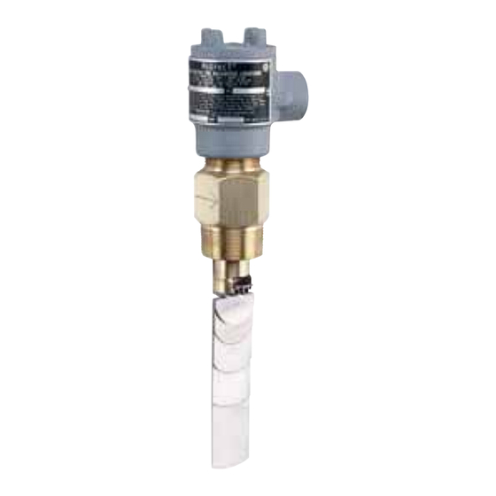
Rugged and reliable the Flotect
automatically to protect equipment and pipeline systems against damage
from reduction or loss of flow. The V4 is time tested being installed in
thousands of pipelines and processing plants around the world. A unique
magnetically actuated switching design gives superior performance.
There are no bellows, springs, or seals to fail. Instead, a free-swinging
vane attracts a magnet within the solid metal switch body, actuating a
snap switch by means of a simple lever arm.
FEATURES
• Leak proof body machined from bar stock
• Choice of custom vane calibrated for your application, Model V4, or field
adjustable multilayer vane, Model V4-2-U (see set point chart on page 4)
• Weatherproof, designed to meet NEMA 4
• Explosion-proof (listing included in specifications)
• Installs directly and easily into pipeline with a thredolet, tee, or flange
(see application drawings on page 4)
• Can be used in pipes 1-1/2˝ and up
• Electrical assembly can be easily replaced without removing the unit
from installation so that the process does not have to be shut down
• High pressure rating of 1000 psig (69 bar) with the brass body and 2000
psig (138 bar) with the 316 SS body
APPLICATIONS
• Protects pumps, motors and other equipment against low or no flow
• Controls sequential operation of pumps
• Automatically starts auxiliary pumps and engines
• Stops liquid cooled engines, machines and processing when coolant
flow is interrupted
• Shuts down burner when air flow through heating coil fails
• Controls dampers according to flow
W.E. ANDERSON DIV., DWYER INSTRUMENTS, INC.
P.O. BOX 358 • MICHIGAN CITY, INDIANA 46361 U.S.A.
Series
V4
Specifications - Installation and Operating Instructions
3-11/32
[84.93]
U.L. AND C.S.A. TYPE
2-1/2
INCLUDES 16 GA.
[63.5]
LEADS, 6 [152.4] LONG.
CENELEC VERSION
INCLUDES TERMINAL
BLOCK.
EXPLOSION-PROOF
HOUSING WITH 3/4
[19.05] CONDUIT
6-3/4
CONNECTION
SWITCH BODY OF SAE
4-11/16
72 BRASS OR 316SS
[119.06]
STAINLESS STEEL
1-1/2 NPT
1 [25.4]
MAGNET KEEPER 430
STAINLESS STEEL
VANE AND VANE BLOCK
316 STAINLESS STEEL
FIVE LAYER VANE
DESIGNED FOR 1-1/2
[38.1] TO 8 [203.2]
PIPES. USABLE IN
LARGER SIZES.
®
V4 flow switch operates
Vane Operated Flow Switch
SPECIFICATIONS
Service: Gases or liquids compatible with wetted materials.
Wetted Materials:
Vane: 316 SS
Body: Brass or 316 SS standard.
Magnet Keeper: 430 SS standard, 316 SS optional.
Options: Other materials also available, consult factory
(e.g. PVC, Hastelloy, Nickel, Monel, Titanium).
Temperature Limit: -4 to 275°F (-20 to 135°C) standard, MT high
temperature option 400°F (205°C) [MT option not UL, CSA, ATEX, or
SAA].
Pressure Limit: Brass body 1000 psig (69 bar), 316 SS body 2000 psig
(138 bar), optional 5000 psig (345 bar) available with 316 SS body and
SPDT switch only.
Enclosure Rating: Weatherproof and Explosion-proof. Listed with UL
and CSA for Class I, Groups C and D; Class II, Groups E, F, and G.
ATEX
0344
II 2 G EEx d IIB T6 -20°C≤Tamb≤75°C
EC-Type Certificate No.: KEMA 03ATEX 2383
SAA: Exd II C T6 (T amb=60°C).
Zone I. Also FM approved.
Switch Type: SPDT snap switch standard, DPDT snap switch optional.
Electrical Rating: UL, FM, ATEX and SAA models 10A @ 125/250 VAC
(V~). CSA models: 5A @ 125/250 VAC (V~); 5A res., 3A ind. @ 30 VDC
(V ). MV option: 1A @125 VAC (V~); 1A res., .5A ind. @ 30 VDC (V ).
MT option: 5A @ 125/250 VAC (V~). [MT and MV option not UL, CSA,
FM, ATEX or SAA].
Electrical Connections: UL and CSA models: 16 AWG, 6˝ (152 mm)
long. ATEX and SAA unit: Terminal block.
Conduit Connection: 3/4˝ female NPT.
Process Connection: 1-1/2˝ male NPT.
Mounting Orientation: Within 5° of vertical for proper operation. Units
for horizontal installation (vertical pipe with up flow) available.
Set Point Adjustment: For universal vane: five vane combinations.
Weight: 4 lb 8 oz (1.9 kg).
Notes:
• Check all ratings given in the instructions and on the product to make
sure that the product is suitable for your application. Do not exceed
electrical ratings, pressure ratings, or temperature ratings of the product.
• Disconnect power supply before beginning installation to prevent
possible equipment damage or electrical shock.
MAINTENANCE
Inspect and clean wetted parts at regular intervals. The cover should be
in place at all times to protect the internal components from dirt, dust, and
weather, and to maintain hazardous location ratings. Disconnect device
from the supply circuit before opening to prevent ignition of hazardous
atmosphere. Repairs to be conducted by Dwyer Instruments, Inc. Units
in need of repair should be returned to the factory prepaid.
Phone: 219/879-8000
Fax: 219/872-9057
Bulletin E-71
www.dwyer-inst.com
e-mail: info@dwyer-inst.com
Publicité
Table des Matières

Manuels Connexes pour W.E. Anderson Flotect V4 Serie

Sommaire des Matières pour W.E. Anderson Flotect V4 Serie
-
Page 9: Détecteur De Débit
Les reparations seront effectùees par Dwyer Instruments, Inc. Tout appareil nécessitant une réparation doit être retourné en usine. Phone: 219/879-8000 www.dwyer-inst.com W.E. ANDERSON DIV., DWYER INSTRUMENTS, INC. Fax: 219/872-9057 e-mail: info@dwyer-inst.com P.O. BOX 358 • MICHIGAN CITY, INDIANA 46361 U.S.A. - Page 10 Exemple V4-SS-316-C-F2S1 Construction Corps laiton – contact SPDT Options Corps inox 316 Construction Corps type 2 Contact DPDT Palette universelle (à supprimer pour palette spéciale) Armature Inox 430 (standard) Aimant Nickel 200 Inox 316 Matière Inox 316 (standard) palette Carpenter 20 Hastelloy B Hastelloy C Monel...
- Page 11 INSTALLATION 1. Enlever les emballages du détecteur et le ruban de l’armature de 3-11/32 l’aimant. ajuster la longueur de la palette si nécessaire, uniquement 84.93 sur la palette multi-couches (voir tableau des débits en dernière 2-23/32 [69,06] page). Installer le détecteur dans le ‘thrédolet’ préalablement soudé DÉGAGEMENT POUR au tuyau.
- Page 12 1-1/2˝ X 1-1/2˝ X 1-1/2˝ Installation standard Installation Té Installation Thredolet 2-1/2˝ 2˝ X 2˝ X 2˝ Installation Té Installation Bride Phone: 219/879-8000 www.dwyer-inst.com W.E. ANDERSON DIV., DWYER INSTRUMENTS, INC. Fax: 219/872-9057 e-mail: info@dwyer-inst.com P.O. BOX 358 • MICHIGAN CITY, INDIANA 46361 U.S.A.