Table des Matières

Sommaire des Matières pour Sensor Partners I-Tec Mini Serie
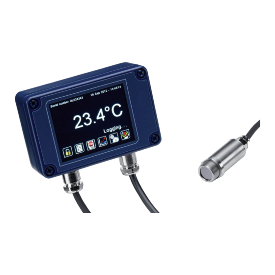
- Page 1 I-Tec Mini Series Operators Guide Guide de l’opérateur pour la série I-Tec Mini I-Tec Mini Bedienungsanleitung Serie I-Tec Mini GuÌa del operario Serie I-Tec Mini Manuale di istruzione...
- Page 2 The I-Tec Mini Series is a range of miniature non-contact infrared temperature sensors with separate electronics modules. All models have an adjustable emissivity setting and are capable of measuring a wide variety of target materials, including food, paper, textiles, plastics, leather, tobacco, pharmaceuticals, chemicals, ruMBer, coal and asphalt.
-
Page 3: Model Numbers
ENVIRONMENTAL Sensing Head Electronics Module Electronics Module (without touch (with touch screen) screen) Environmental Rating IP65 (NEMA 4) IP65 (NEMA 4) – Ambient Temperature See table of Model 0°C to 60°C 0°C to 60°C Range Numbers Relative Humidity Maximum 95% Maximum 95% Maximum 95% non-condensing... -
Page 4: Field Of View
SENSING HEAD OPERATING TEMPERATURE RANGE 0°C to 60°C 0°C to 180°C The high ambient temperature sensing head on -HT models is capable of withstanding temperatures of up to 180°C without cooling. It is available with 20:1 optics. There is no need to supply cooling air or water, and the miniature sensing head is much smaller than bulky, cooled sensors. - Page 5 EXAMPLE: I-TEC MINI-MT-130-CT-MBT Series Sensing Head Optics Temperature Output and Operating Range Interface Temperature I-Tec Mini -MT 0°C to 60°C -130 30:1 -CT configurable MBT RS485 Modbus I-Tec Mini divergent within the limits: output and two alarm -20 to 1000 °C relay outputs, with touch screen EMISSIVITY ADJUSTMENT (-I MODELS)
-
Page 6: User Interface
USER INTERFACE Default View Temperature View Displays a large indication of the measured temperature. The background turns bright red when an alarm is activated. Press “°C” to switch to °F and vice versa. The units are changed throughout Setting the interface. Temperature Units Press the temperature display to select which reading is shown:... - Page 7 Lock/Unlock Prevents settings being changed via a four-digit numerical code. The default password is 1234. Change Password Enter, confirm and save a new four-digit code. Start/Stop Logging Manually begins or ends data logging (requires MicroSD Card, available separately). If Scheduled Start is enabled in Settings > Data Logging, then logging cannot be started manually.
- Page 8 SETTINGS Date & Time Change the date and time for data logging purposes. The clock is reset when the power is cycled unless a battery is fitted. Output Processing Set the time, in seconds, over which the measured temperature is averaged. Averaging Note: averaging prevents the sensor from following rapid temperature Period...
- Page 9 SETTINGS (continued) Emissivity and Compensation Enter the emissivity of the target. Target emissivity can be determined Emissivity experimentally, or estimated using an emissivity table. For more information, Setting contact I-Tec. Minimum: 0.2. Maximum: 1.0. If enabled, compensates for errors caused by reflected energy from hotter or Enable Reflected colder objects.
- Page 10 SETTINGS > ALARMS Alarm 1 and Alarm 2 The temperature at which the alarm is triggered. Minimum: -20°C. Maximum: Alarm Set 1000°C. Point The temperature difference between the Alarm Set Point and the reset Hysteresis temperature. Hysteresis is only used when Automatic Reset is enabled. Please see the diagrams below for more information Minimum: 0°C (hysteresis disabled).
- Page 11 ALARM OPERATION WITH HYSTERESIS & AUTOMATIC RESET Low Alarm with Automatic Reset High Alarm with Automatic Reset Temperature Temperature Alarm Set Point Hysteresis Hysteresis Alarm Set Point Time Time Alarm triggered Alarm reset Alarm triggered Alarm reset DATA LOGGING (-IT AND -MBT MODELS) The I-Tec Mini can be used as a standalone data logger.
-
Page 12: Dimensions
INSTALLATION OF MICROSD CARD AND BATTERY MicroSD Card Battery (use 1 x BR 1225 3V) DATA LOG FILES Data is saved to the MicroSD Card in .csv format. This file format can be opened or imported by spreadsheet software such as Microsoft Excel. A new folder is created on the MicroSD Card for each day that data is logged. -
Page 13: Accessories
Fixed Mounting Bracket (FBS) Adjustable Mounting Bracket (ABS) M16 Clearance 60° Rotation 2 x Mounting Holes M4 Clearance 2 x Mounting Holes M4 Clearance 60° Rotation 60° Rotation ACCESSORIES A range of accessories to suit different applications and industrial environments is available. These may be ordered at any time and added on-site. -
Page 14: Preparation
INSTALLATION The installation process consists of the following stages: Preparation Mechanical installation Electrical installation Please read the following sections thoroughly before proceeding with the installation. PREPARATION Ensure that the sensor is positioned so that it is focused on the target only. DISTANCE AND SPOT SIZE The size of the area (spot size) to be measured determines the distance between the sensor and the target. -
Page 15: Power Supply
To minimise electromagnetic interference or ‘noise’, the sensor should be mounted away from motors, generators and such like. POWER SUPPLY Be sure to use a 24 V DC (100 mA) power supply. MECHANICAL INSTALLATION All sensors come with a 1 m cable and a mounting nut as standard. Longer cables are available to order. - Page 16 WIRING (ALL MODELS) Check the distance between the sensing head and the electronics module, and between the electronics module and the instrumentation. If necessary, the sensor can be ordered with a longer cable between the sensing head and the electronics module. The output cable from the electronics module should have an outer diameter between 3.0 and 6.5 mm, with conductors of size 28 to 18 AWG.
- Page 17 Address Length Description R/W/MW (words) 0x06 Unfiltered object temperature 0x08 Sensor temperature 0x0A Maximum temperature over hold period 0x0C Minimum temperature over hold period 0x0E Average temperature over hold period 0x10 Filtered object temperature 0x12 PI temperature 0x14 Emissivity (1 LSB = 0.0001) Minimum 0.2000, Maximum 1.0000 0x16 Reflected temperature...
-
Page 18: Important
Address Length Description R/W/MW (words) 0x28 Alarm 2 status register R/W/MW Bit 0 – Relay triggered (R) Bit 1 – Visible alarm active (R) Bit 2 – Alarm triggered (R) Bit 3 – Auto reset (1)/manual reset (0) (R/W/ Bit 4 – Alarm acknowledge (R/W/MW) Bit 5 –... -
Page 19: Lens Cleaning
MAINTENANCE Our customer service representatives are available for application assistance, calibration, repair, and solutions to specific problems. Contact our Service Department before returning any equii-Tec Minient. In many cases, problems can be solved over the telephone. If the sensor is not performing as it should, try to match the symptom below to the problem. -
Page 20: Spécifications
La série I-Tec Mini est une gamme de mini-capteurs de température infrarouge avec électronique séparée. Tous les modèles disposent d’un réglage d’émissivité et sont capables de mesurer une grande variété de matériaux : nourriture, papier, textiles, plastiques, cuir, tabac, produits pharmaceutiques, produits chimiques, caoutchouc, charbon et l’asphalte. L’option écran tactile permet l’indication de température, les alarmes, la configuration du capteur et l’enregistrement des données sur carte MicroSD. -
Page 21: Environnement
Câble (tête de mesure / électronique) 1 m (standard) jusqu’à 30 m (option) Poids avec 1 m Cable 390 g (approx) Raccordements Bornier débrochable (voir schéma de raccordement) taille du conducteur 0.3102 mm² Presse étoupe Câble diametres 3.0 to 6.5 mm ENVIRONNEMENT Capteur Interface Electron-... -
Page 22: Température De Fonctionnement Du Capteur -Ma -Ha
TEMPÉRATURE DE FONCTIONNEMENT DU CAPTEUR 0°C à 60°C 0°C à 180°C Le capteur type HA est capable de fonctionner sans refroidissement jusqu’à des températures ambiantes de180°C. Valable avec une optique 20:1. Il n’est pas nécessaire d’alimenter le capteur en air ou en eau, ce qui permet d’utiliser un capteur plus petit que ceux avec système de refroidissement. -
Page 23: Réglage D'émissivité (Modèles I)
EXAMPLE: I-TEC MINI-MA-130-CT-MBT Series Température de Champs Température de Sorties et Interface fonctionnement de vue mesure du capteur I-Tec Mini -MT 0°C à 60°C -130 -CT configurable MBT Sortie RS485 I-Tec Mini 30:01 -20 à 1000 °C Modbus et 2 sorties alarmes relais, avec écran RÉGLAGE D’ÉMISSIVITÉ... -
Page 24: Interface Utilisateur
INTERFACE UTILISATEUR Affichage par Temperature défaut Presser “°C” pour passer en °F Sélection de l’unité Cette icône s’affiche lorsqu’une carte SD est insérée, et clignote lorsque la journalisation des données est en cours. Cette icône s’affiche lorsque l’enregistrement des données est programmé et prêt à... - Page 25 Courbes RAZ des courbes Défilement en temps réel de la mesure Acquittement des alarmes Réglages Appuyer sur pour sauvegarder ou pour quitter sans sauvegarde. SETTINGS Date et heure Traitement du signal de sortie Echantillonnage de la moyenne Averaging Period Mode mémoire: Hold Mode Peak - Pic Valley - Creux...
- Page 26 Enregistrement de données Période échantillonnage Sample Period Nombre d’échantillons Number of Samples Programmation du début enregistrement Enable Scheduled Start Date et heure Date and Time Emissivité et Compensation Réglage émissivité Emissivity Setting Activation de compensation d’énergie Reflectée Enable Reflected Energy Compensation Reflected Temperature réflectée...
- Page 27 SETTINGS (continued) Alarmes Réinitialisation des alarmes SETTINGS > ALARMS Alarme 1 et Alarme 2 Réglage seuil Alarm Set Point Hystéresis Hysteresis Temperature mesurée / température capteur (alarme 2) Filtered Temperature or Sensor Temperature (Alarm 2 only) Alarmes: Alarm Type High - Haute Low - Basse Off - Off RAZ:...
-
Page 28: Alarme Avec Hystéresis Et Raz Automatique
ALARME AVEC HYSTÉRESIS ET RAZ AUTOMATIQUE Alarme basse avec RAZ automatique Alarme haute avec RAZ automatique Temperature Temperature Réglage seuil Hystéresis Hystéresis Réglage seuil Heure Heure Alarme activée Alarme réinitialisée Alarme activée Alarme réinitialisée ENREGISTREMENT DE DONNES(-IT ET -MBT) La I-Tec Mini peut être utilisé comme enregistreur de données autonome. Les I-Tec Mini IT et MBT ont un slot pour MicroSD card. -
Page 29: Installation De La Microsd Card Et De La Batterie
INSTALLATION DE LA MICROSD CARD ET DE LA BATTERIE MicroSD Card 1 Batterie type BR1225 FICHIERS D’ENREGISTREMENTS Fichiers d’enregistrements Les données sont enregistrées sur la carte MicroSD en format CSV. Ce format de fichier peut être ouvert ou importé par un tableur type Microsoft Excel. Un nouveau dossier est créé... -
Page 30: Accessoires
Support de montage fixe (FBS) Support de fixation réglable (ABS) Rotation 60° Montage trous: M4 Montage trous: M4 60° Rotation Rotation 60° ACCESSOIRES Une gamme d’accessoires pour s’adapter aux applications et environnements industriels est disponible chez I-Tec. Ils peuvent être commandés à tout moment et a rajouté sur l’application existante. - Page 31 INSTALLATION Le processus d’installation consiste aux étapes suivantes : Préparation Installation mécanique Installation électrique Il faut lire les sections suivantes attentivement avant de commencer l’installation. PRÉPARATION S’assurer que le détecteur est mis en place pour qu’il ne se concentre que sur la cible. DISTANCE ET TAILLE DU POINT La taille de la zone (taille du point) qui doit être mesurée détermine la distance entre le détecteur et la cible.
-
Page 32: Interférence Électrique
INTERFÉRENCE ÉLECTRIQUE Pour réduire l’interférence électromagnétique ou ‘bruit’, le détecteur devrait être monté à l’écart de moteurs, générateurs, et autres appareils similaires. ALIMENTATION Veillez à utiliser un bloc d’alimentation DC 24 V (100 mA). INSTALLATION MÉCANIQUE Tous les détecteurs sont fournis avec un câble d’un mètre et un boulon de fixation. Des câbles plus longs sont disponibles à... -
Page 33: Modbus Sur Liaison Série
CÂBLAGE (TOUS MODÈLES) Vérifier la distance entre la tête de capteur et le module électronique, et entre le module électronique et l’instrumentation. Si nécessaire, le capteur peut être commandé avec un câble plus long entre la tête de mesure et le module électronique. En sortie du module électronique le câble doit avoir un diamètre extérieur compris entre 3,0 et 6,5 mm, avec des conducteurs de 0.3102 mm à... - Page 34 Adresse Longueur Déscription R/W/MW (mots) 0x06 Température object non filtrée 0x08 Température du capteur 0x0A Température Maximum sur la période d’acquisition 0x0C Température Minimum sur la période d’acquisition 0x0E Température Moyenne sur la période d’acquisition 0x10 Filtre de temperature objet 0x12 Température PI 0x14...
-
Page 35: Fonctionnement
Adresse Longueur Déscription R/W/MW (mots) 0x28 Alarm 2 registre d’état R/W/MW Bit 0 – alarme active (R) Bit 1 – Alarme visuelle active (R) Bit 2 – alarme active (R) Bit 3 – RAZ auto (1)/RAZ manuelle (0)(0) (R/W/ Bit 4 – Alarme acquitée (R/W/MW) Bit 5 –... -
Page 36: Mesure De Temperature Via Capot De Protection
MESURE DE TEMPERATURE VIA CAPOT DE PROTECTION La I-Tec Mini est capable de mesurer la température d’une cible à travers uncapot constituée d’un matériau transparent au rayonnement infrarouge à 8-14 microns. Le réglage d’émissivité du capteur doit être ajustée pour compenser la présence de la fenêtre plastique. Contacter I-Tec pour plus d’informations sur l’utilisation du I-Tec Mini avec un capot de protection. - Page 38 Die I-Tec Mini Serie besteht aus mehreren berührungslos arbeitenden Infrarot Miniatur- Sensoren (Pyrometern) mit separaten elektronischen Komponenten. Alle Modelle aben einen einstellbaren Emissionsgrad und können sehr verschiede Materialien einschließlich Lebensmitteln, Papier, Textilien, Kunststoffe, Leder, Tabak, pharmazeutische Produkte Chemikalien, Gummi Kohle und Asphalt messen.
- Page 39 UMWELTBESTIMMUNGEN Sensorkopf Elektronik (ohne Elektronik (mit Touchscreen) Touchscreen) Schutzart IP65 (NEMA 4) IP65 (NEMA 4) Umgebungstemper- siehe Tabelle der 0°C bis 60°C 0°C bis 60°C aturbereich einzelnen Modelle Relative Feuchte max. 95% nicht max. 95% nicht kon- max. 95% nicht kon- kondensierend densierend densierend...
- Page 40 ARBEITSTEMPERATURBEREICH DES MESSKOPFES 0°C bis 60°C 0°C bis 180°C Der Temperaturmesskopf für hohe Umgebungstemperaturen der -HA-Typen kann bei Temperaturen bis zu 180°C ohne Kühlung arbeiten. Kühlluft oder Wasser sind nicht notwendig; der Miniaturmesskopf ist wesentlich kleiner als platzraubende, gekühlte Pyrometer. FIELD OF VIEW Entfernung: zwischen Sensor Entfernung: zwischen Sensor...
- Page 41 BEISPIEL: I-TEC MINI-MA-130-CT-MBT Serien Arbeitstemperatur- Sichtfeld Messtemperaturbereich Ausgang und bereich des Interface Messkopfes I-Tec -MT 0°C bis 60°C -130 30:1 -CT 4 bis 20 mA MBT RS485 Mini divergent konfigurierbar innerhalb Modbus I-Tec dieses Bereichs: -20°C bis Ausgangund Mini 1000°C zwei Alarm- Relaisausgänge, mit Touchscreen...
- Page 42 BENUTZER INTERFACE Voreingestell- Temperaturwert ter Wert Drücken Sie „°C“ um zwischen „°F“ zu wechseln und umgekehrt. Die Einstellung Einheiten können durchgehend im Interface geändert werden. der Tempera- tureinheiten MicroSD Card eingesteckt Vorgesehene Datenspeicherung freigegeben Liste der Temperaturen Gefiltert Temperatur Filtered Temp: Unfiltered Ungefiltert Temperatur...
- Page 43 Sperren und Entsperren Das voreingestellte Passwort lautet 1234. Passwortänderung Start Datenspeicherung Stop Datenspeicherung Temperaturkurve Setzen Sie den Graph Echtzeitansicht Alarme quittieren Einstellungen Drücken Sie um die Einstellungen zu sichern oder um den Bild- schirm ohne Sicherung zu verlassen.
- Page 44 EINSTELLUNGEN Datum & Zeit Aufbereitung des Ausgangssignals Zeit zur Mittelwertsberechnung Averaging Period Haltemodus: Hold Mode Peak - Spitze Valley - Tal Off - Aus Zeitraum von halten Hold Period Datenspeicherung Speicherdauer Sample Period Anzahl der Messwerte Number of Samples Geplanten Start freigeben Enable Scheduled Start...
- Page 45 EINSTELLUNGEN Emissionsgrad und Kompensation Emissionsgradeinstellung Emissivity Setting Freigabe zur Kompensation der reflektierten Energie Enable Reflected Energy Compensation Reflected Temperatur des reflektierte Energie Temperature 4 bis 20 mA Ausgabe (-IT-Modelle) Temperatur bei 4 mA Temperature at 4 mA Temperatur bei 20 mA Temperature at 20 mA Modbus-Adresse (-MBT-Modelle)
- Page 46 EINSTELLUNGEN > ALARME Alarm 1 und Alarm 2 Eingestellter Alarmauslösepunkt Alarm Set Point Hysterese Hysteresis Gefilterte Temperatur oder Sensortemperatur (nur Alarm 2) Filtered Temperature or Sensor Temperature (Alarm 2 only) Alarmtyp Alarm Type High - Obergrenze Low - Untergrenze Zurücksetzen Reset Automatic –...
- Page 47 DATEN-AUFZEICHNUNG (-IT UND -MBT MODELLE) Der I-Tec Mini kann als unabhängiges Datenaufzeichnungsgerät verwendet werden. Die I-Tec Mini-Modelle -IT und -MBT beinhalten einen Steckplatz für MicroSD-Karten zur Datenaufzeichnung. Dieser kann über die Touchscreen-Oberfläche konfiguriert werden. Der Benutzer kann die Probenrate und die Anzahl der aufzunehmenden Proben auswählen und einen bestimmten Zeitpunkt für den Beginn der Datenaufzeichnung ansetzen.
- Page 48 INSTALLATION VON MICROSD-KARTEN UND BATTERIEN MicroSD-Karte Batterie (verwenden Sie 1 x BR 1225 3V) DATENAUFZEICHUNGSDATEIEN Daten werden auf der MicroSD-Karte im Format .csv gespeichert Dieses Dateiformat kann mit Tabellenkalkulationsprogrammen wie Microsoft Excel geöffnet und importiert werden. Für jeden Tag, an dem Daten aufgezeichnet werden, wird auf der MicroSD-Karte ein neuer Ordner erstellt.
- Page 49 Feste Halterung (FBS) Justierbare Halterung (ABS) M16 Clearance 60° Rotation 2 x Mounting Holes M4 Clearance 2 x Mounting Holes M4 Clearance 60° Rotation 60° Rotation ZUBEHÖR Für verschiedene Anwendungen und industrielle Umgebungen ist eine Auswahl von anderem Zubehör verfügbar. Dieses kann jederzeit bestellt und vor Ort angebracht werden. Das folgende Zubehör ist verfügbar: Feste Halterung (Abmessungen siehe oben): Erlaubt die Justierung durch eindimensionale Drehung.
- Page 50 NSTALLATION Der Installationsprozess besteht aus den folgenden Phasen: Vorbereitung Mechanische Installation Elektrische Installation Bitte lesen Sie sich die folgenden Abschnitte sorgfältig durch, bevor Sie mit der Installation beginnen. VORBEREITUNG Achten Sie darauf, dass der Sensor nach dem Aufstellen nur auf das Ziel weist. ENTFERNUNG UND ZIELPUNKTGRÖSSE Die Größe des Messbereichs (Zielpunktgröße) bestimmt die Entfernung zwischen Sensor und Ziel.
-
Page 51: Mechanische Installation
Um elektromagnetische Störungen oder “Lärm” auf ein Minimum zu reduzieren, sollte der Sensor entfernt von Motoren, Generatoren und ähnlichen Geräten aufgestellt werden. NETZSPANNUNG Achten Sie darauf, dass Sie 24 V Gleichstrom (100 mA) verwenden.. MECHANISCHE INSTALLATION Alle Sensoren werden mit einem 1m langem Kabel und einer Befestigungsmutter geliefert. Längere Kabel können bestellt werden. - Page 52 VERDRAHTUNG (ALLE MODELLE) Überprüfen Sie den Abstand zwischen dem Sensorkopf und dem Elektronikmodul und zwischen dem Elektronikmodul und der Geräteausstattung. Der Sensor kann falls nötig mit einem längeren Kabel zwischen dem Sensorkopf und dem Elektronikmodul bestellt werden. Das Ausgangskabel des Elektronikmoduls sollte einen äußeren Durchmesser zwischen 3,0 und 6,5 mm haben, mit Leitern der Größe 28 bis 18 AWG.
- Page 53 Adresse Länge Beschreibung R/W/MW (Worte) 0x06 ungefilterte Objekttemperatur 0x08 Sensor Temperatur 0x0A max. Temperatur Halteperiode 0x0C min. Temperatur Halteperiode 0x0E durchschnittl. Temperatur Halteperiode 0x10 gefilterte Objekttemperatur 0x12 PI-Temperatur 0x14 Emissionsgrad (1 LSB = 0.0001) Minimum 0.2000, Maximum 1.0000 0x16 reflektierte Temperatur 0x18 Sensor-Status R/W/MW...
- Page 54 Adresse Länge Beschreibung R/W/MW (Worte) 0x28 Statusverzeichnis Alarm 2 R/W/MW Bit 0 – Relais ausgelöst(R) Bit 1 – Sichtbarer Alarm aktiv (R) Bit 2 – Alarm ausgelöst (R) Bit 3 – Auto Rücksetzung (1)/manuelle Rücksetzung (0) (R/W/MW) Bit 4 – Alarm Quittierung (R/W/MW) Bit 5 –...
- Page 55 MESSUNG DURCH EINE SCHEIBE Der Pyro Mini kann die Temperatur eines Ziels durch eine Scheibe aus für Infrarotstrahlung von 8-14 Mikron durchlässigem Material messen. Die Emissionseinstellung des Sensors sollte angepasst werden, um die vorhandene Scheibe auszugleichen. Für mehr Informationen zur Verwendung des I-Tec Mini mit einer Scheibe kontaktieren Sie bitte I-Tec.
-
Page 56: Especificación General
La serie I-Tec Mini es una gama de sensores de temperatura en miniatura sin contacto por infrarrojos la electrónica separada. Todos los modelos tienen un ajuste de la emisividad y son capaces de medir en una gran variedad de materiales, incluyendo alimentos, papel, textiles, plásticos, cuero, tabaco, productos farmacéuticos, productos químicos, caucho, carbón y asfalto. -
Page 57: Números De Modelo
AMBIENTAL Sensor Módulo electrónico Módulo electrónico (sin pantalla táctil) (con pantalla táctil) Protección Ambiental IP65 (NEMA 4) IP65 (NEMA 4) Temperatura ambiente consulte la tabla de 0°C a 60°C 0°C a 60°C números de modelo Humedad relativa Máxima 95% sin Máxima 95% sin Máxima 95% sin condensación... -
Page 58: Campo De Visión
GAMA DE TEMPERATURAS DE FUNCIONAMIENTO DEL SENSOR 0°C a 60°C 0°C a 180°C Los sensores para alta temperatura ambiente modelos -HA son capaces de soportar temperaturas de hasta 180 ° C sin refrigeración. Están disponibles con óptica de 20:1. No es necesario suministrar enfriamiento por aire o agua por lo que el sensor en miniatura es mucho más pequeño que los voluminosos sensores refrigerados. - Page 59 EJEMPLO - I-TEC MINI-MA-130-CT-IT Serie Cabeza Campo Rango de Salida e interfaz medidora rango de visión temperatura de de temperatura medición I-Tec Mini -MT 0°C a 60°C -130 30:1 -CT configurable MBT salida RS485 I-Tec Mini -20 a 1000°C Modbus y dos salidas de relé...
-
Page 60: Interfaz De Usuario
INTERFAZ DE USUARIO Vista por Temperatura defecto Presione “° C” para cambiar a ° F y viceversa. Las unidades se cambian a lo Ajuste largo de toda la interfaz. unidades temperatura Filtered temp - Temperatura filtrada Para seleccionar Average temp - Temperatura media Unfiltered temp - Temperatura sin filtrar la tempera- tura indicada... - Page 61 Bloquear y desbloquear (Lock/Unlock) La contraseña por defecto es 1234. Cambiar contraseña Iniciar sesión Detener sesión Gráfico de temperatura (Graph) Reiniciar el gráfico Vista con desplazamiento en tiempo real Reconocer alarmas Configuración (Settings) Pulse aplicar para guardar la configuración o salir para salir de la pantalla sin guardar los cambios.
- Page 62 SETTINGS Fecha hora (Date and Time) Procesamiento de salida (Output Processing) Período para hacer la media Averaging Period Modo de visualización del pico o el Valle apagado Hold Mode Hold Period Período de mantenimiento Hold Period Registro de datos (Data Logging) Período de la muestra Sample Period...
- Page 63 SETTINGS (continued) Emisividad y compensación (Emissivity and Compensation) Ajuste de emisividad Emissivity Setting Permitir la compensación de la energía reflejada Enable Reflected Energy Com- pensation Reflected Temperatura reflejada Temperature 4 a 20 mA de salida (modelos -IT) (4-20 mA output) Temperatura a 4 mA Temperature at 4 mA...
- Page 64 SETTINGS > ALARMS Alarma 1 y alarma 2 Punto de ajuste de alarma Alarm Set Point Histéresis Hysteresis Temperatura Filtrada o temperatura del Sensor (sólo alarma 2) Filtered Temperature / Sensor Temperature Tipo Alarma: Alarm Type High - alto Low - bajo Off - apagado Reinicio Reset...
- Page 65 REGISTRO DE DATOS (MODELOS -IT Y - MBT) El I-Tec Mini puede utilizarse como un registrador de datos independiente. Los modelos I-Tec Mini -IT y - MBT incluyen una slot para tarjetas MicroSD para registro de datos, que puede configurarse mediante la Interfaz de la pantalla táctil. El usuario puede seleccionar la frecuencia de muestreo y el número de muestras a tomar y programar que el registro de datos empiece en un momento determinado.
- Page 66 INSTALACIÓN DE LA TARJETA MICROSD Y BATERÍA Tarjeta MicroSD Batería (1 x 3V BR 1225) ARCHIVOS DE REGISTRO DE DATOS Los datos se guardan en la tarjeta MicroSD en formato CSV. Este formato de archivo puede ser abierto o importado por software de hoja de cálculo como Microsoft Excel. Se creará...
- Page 67 Soporte de montaje fijo (FBS) Soporte de montaje ajustable (ABS) Rotación de 60 ° 2 x orificios de montaje M4 2 x orificios de montaje M4 Rotación de 60 ° Rotación de 60 ° ACCESORIOS Hay disponible una gama de accesorios para adaptarse a diferentes aplicaciones y entornos industriales.
- Page 68 INSTALACIÓN El proceso de instalación consiste en las siguientes etapas: Preparación Instalación mecánica Instalación eléctrica Leer las siguientes secciones con detenimiento antes de proceder a la instalación. PREPARACIÓN Asegurarse de que el sensor se coloca de manera que esté enfocando solamente a la diana. DISTANCIA Y TAMAÑO DE LA ZONA DE MEDICIÓN El tamaño de la zona de medición a medir determina la distancia entre el sensor y la diana.
-
Page 69: Suministro Eléctrico
SUMINISTRO ELÉCTRICO Asegurarse de usar un suministro eléctrico de 24Vcc (100mA). INSTALACIÓN MECÁNICA Todos los sensores vienen con 1 metro de cable y una tuerca de montaje. Están disponibles bajo pedido Cables más largos. Sensor puede ser instalado en una consola o dispositivos de diseño propio, o puede usar los accesorios de consola fija y regulable de montaje que se muestran debajo. - Page 70 CABLEADO (TODOS LOS MODELOS) Compruebe la distancia entre la cabeza medidora y el módulo electrónico y entre el módulo electrónico y la instrumentación. Si es necesario, el sensor se puede pedir con un cable más largo entre la cabeza medidora y el módulo electrónico. El cable de salida del módulo de electrónica debe tener un diámetro exterior entre 3.0 y 6.5 mm, con conductores de tamaño de 28 a 18 AWG.
- Page 71 Dirección Longitud Descripción R/W/MW (palabras) 0x06 Temperatura sin filtrar del objeto 0x08 Temperatura del cabezal sensor 0x0A Temperatura máxima durante el periodo de retención 0x0C Temperatura mínima durante el periodo de mantenimiento 0x0E Temperatura media durante el período de espera 0x10 Temperatura filtrado del objeto 0x12...
- Page 72 Dirección Longitud Descripción R/W/MW (palabras) 0x28 Registro del estado de alarma 2 R/W/MW Bit 0 – relé activado (R) Bit 1 – alarma Visible activa (R) Bit 2 – alarma activada (R) Bit 3 – Auto reset (1) / reset manual (0) (R/W/MW) Bit 4 –...
-
Page 73: Limpieza De La Lente
VISUALIZACIÓN A TRAVÉS DE UNA VENTANA El I-Tec Mini es capaz de medir la temperatura de un objetivo a través de una ventana de un material que sea transmisivo a la radiación infrarroja en 8-14 micras. El ajuste de emisividad del sensor debe ser ajustado para compensar la presencia de la ventana. -
Page 74: Dati Tecnici
Nei sensori pirometrici non a contatto serie I-Tec Mini la sonda di misura della temperatura è di dimensioni molto ridotte ed è collegata a distanza alla sua centralina elettronica separata. Per tutti i modelli si può regolare l’emissività nell’elettronica separata. Così si può misurare la temperature di svariati materiali e prodotti come: alimentari, carta, tessili, plastiche, tabacco, pellame, prodotti farmaceutici e chimici, carbone, asfalto, ecc. - Page 75 Lunghezza del cavo (dalla sonda alla centralina) 1 m (standard), fino a 30 m (opzionale) Peso con1 m di cavo 390 g (circa) Connessione dei cavi Terminali accessibili rimuovendo le 4 viti del coperchio (vedi pag 12). Sezioni dei cavi: da 28 a 18 AWG Manicotto passacavo Per cavi di diametro da 3.0 a 6.5 mm...
- Page 76 TEMPERATURA OPERATIVA DELLA SONDA da 0°C a 60°C da 0°C a 180°C La sonda HA impiegata in ambienti con elevate temperature resiste fino a 180°C senza l’impiego di elementi aggiuntivi di raffreddamento. Viene fornita con ottica di risoluzione 20:1. La sonda HA mantiene quindi le sue dimensioni ridotte in ambienti molto caldi senza dovere impiegare ingombranti camicie di raffreddamento.
- Page 77 ESEMPIO: I-TEC MINI-MA-130-CT-MBT Serie Temperatura Risoluzione Gamma di Uscite ed operativa della ottica misura della interfacce sonda temperatura I-Tec Mini -MT da 0°C a -130 30:1 -CT Configurabile MBT uscita RS485 I-Tec Mini 60°C divergente in tutta la gamma Modbus e due allarmi da -20°C a 1000°C a relè, con schermo a sfioro...
-
Page 78: Descrizione Dello Schermo
DESCRIZIONE DELLO SCHERMO Icone in Lettura delle temperature Cifre molto visibili della temperature misurata e lettura facilitata dello schermo default grazie alle icone . Lo sfondo nero diventa rosso quando è attivato un allarme. Le unità di misura sono selezionate direttamente sullo schermo. Premere su Selezione in “... - Page 79 Password di sicurezza Codice numerico di 4 cifre per prevenire la manomissione dei valori Impostati. La posizione di blocco impedisce nuove programmazioni. La password di default è 1234. Cambio di password Digitare, confermare e salvare un nuovo codice a quattro cifre. Start/Stop della acqisizione dei dati Avviamento manuale della raccolta dei dati (GO), premendo “STOP”...
-
Page 80: Selezione Dei Programmi
SELEZIONE DEI PROGRAMMI Data e ora Impostare data e ora ai fini dell’acqisizione dati. (con scheda MicroSD). L’orologio è disattivato fino a che non viene inserita la batteria nel suo ap- posito alloggiamento sotto il coperchio dello schermo. Elaborazione di uscita Questa schermata, come tutte le altre di questa sezione, la si imposta facilmente premendo i pulsanti riportanti i simboli rappresentati nella colonna di sinistra. - Page 81 SELEZIONE DEI PROGRAMMI Emissività e Compensazione Rilevare l’emissività dell’oggetto da misurare. Ciò può essere fatto in via Impostazione sperimentale o confrontando una tabella riportante i dati di emissività dei vari della emis- materiali (Contattare I-Tec). Valore minimo 0.2 max. 1.0 sività...
- Page 82 PROGRAMMAZIONE DEGLI ALLARMI Allarme 1 e Allarme 2 Temperatura alla quale scatta l’allarme (set-point ). Minimo -20°C, Massimo Impostazione 1000°C. del set-point La differenza di temperatura tra quella impostata come set-point e quella di Isteresi reset dell’allarme. L’isteresi è usata solo nella modalità di reset automatico. (Vedi diagramma alla pagina successiva).
- Page 83 ISTERESI SUGLI ALLARMI E RESET AUTOMATICO Allarme basso con reset automatico Allarme alto con reset automatico Temperatura Temperatura Set Point dell’allarme Isteresi Isteresi Set Point dell’allarme Tempo Tempo Allarme attivato Allarme disattivato Allarme attivato Allarme disattivato RACCOLTA DEI DATI (MODELLI –IT E MBT) Il I-Tec Mini può...
- Page 84 INSTALLAZIONE DELLA SCHEDA MICROSD E DELLA BATTERIA Scheda MicroSd Batteria (usare 1 x BR 1225 3V) FILES DELLA ACQISIZIONE DATI I dati salvati nella scheda MicroSD hanno il formato .csv. I file di questo formato possono essere aperti o importati da fogli di calcolo software, come per esempio Microsoft Excel. Viene creata una nuova cartella nella scheda MicroSD Card per ogni giorno in cui i dati sono stati raccolti.
- Page 85 Squadretta di montaggio fissa (FBS) Squadretta di montaggio regolabile (ABS) 60° Rotazione max. 2x fori di fissaggio M4 2x fori di fissaggio M4 60° Rotazione 60° Rotazione max. max. ACCESSORI Sono disponibili diversi accessori adatti a differenti applicazioni nel settore industriale. Questi accessori possono essere acquistati anche successivamente e applicati dal cliente in campo.
- Page 86 INSTALLAZIONE Il processo di installazione consiste nelle seguenti fasi: Preparazione Installazione meccanica Installazione elettrica Si prega di leggere interamente le seguenti sezioni prima di procedere all’installazione. PREPARAZIONE Assicurarsi che il sensore pirometrico sia posizionato in modo di essere focalizzato sull’oggetto di cui si deve misurare la temperatura DISTANZA E DIMENSIONE SPOT In base al cono utile (spot) che parte dal sensore ( vedi disegno sopra riportato) la dimensione...
-
Page 87: Installazione Meccanica
ALIMENTAZIONE Controllare che l’alimentazione sia 24 Vcc (100 mA) INSTALLAZIONE MECCANICA I sensori sono forniti con cavo di 1 m e dado di fissaggio, sono fornibili cavi più lunghi, da stabilire all’ordine. Per il montaggio sulla parte terminale filettata tramite squadrette fisse o regolabili come quelle fornibili dalla casa o di proprio disegno. - Page 88 CABLAGGIO (PER TUTTI I MODELLI) Per prima cosa verificare le distanze tra sonda e centralina e tra centralina e la strumentazione a valle. Se necessario ordinare la sonda con un cavo della lunghezza richiesta per poterla collegare comodamente alla sua centralina. I cavi che escono dalla centralina dovreMBero avere un diametro compreso tra 3,0 e 6.5 mm con conduttori terminali di dimensione da 28 a 18 AWG.
- Page 89 Indirizzo Lunghezza Descrizione R/W/MW (parole) 0x06 Temperatura non filtrata dell’oggetto 0x08 Temperatura del sensore 0x0A Temperatura massima nel periodo considerato 0x0C Temperatura minima nel periodo considerato 0x0E Temperatura media nel periodo considerato 0x10 Temperatura filtrata dell’oggetto 0x12 Temperatura del circuito stampato 0x14 Impostazione Emissività...
-
Page 90: Avvertenze
Indirizzo Lunghezza Descrizione R/W/MW (parole) 0x28 Allarme 2 - Registro degli stati R/W/MW Bit 0 – Relè impostato (R) Bit 1 – Allarme visivo attivo (R) Bit 2 – Allarme impostato (R) Bit 3 – Reset Auto (1)/Reset manual (0) (R/W/ Bit 4 –... - Page 91 MANUTENZIONE Salvo che per una periodica pulizia dell’ottica il sensore non richiede una particolare manutenzione. In caso di cattivo funzionamento chiedere all’agente locale consigli per l’eliminazione del problema avva- lendosi della sottostante tabella diagnostica. Solo in caso di non risolvere il problema dopo questo contatto rimandare il sensore alla Casa o all’agente locale per un più...
- Page 92 Sensor Partners BV Sensor Partners BVBA Drunen - Nederland Zellik - België info@sensor.nl info@sensors.be www.sensor.nl www.sensors.be +31 (0)416 - 37 83 49 +32 (0)2 - 464 96 90 www.sensor.nl...