Table des Matières
Publicité
Les langues disponibles
Les langues disponibles
Liens rapides
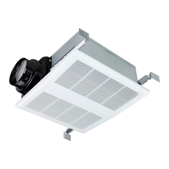
MODEL: ODS-8003-14
ODS-8003HS-14
WARNING
TO REDUCE THE RISK OF FIRE, ELECTRIC SHOCK, OR INJURY TO PERSONS, OBSERVE THE FOLLOWING:
1. Use this unit only in the manner intended by the manufacturer. If you have questions, contact the manufacturer at the
address or telephone number listed in the warranty.
2. Before servicing or cleaning unit, switch power off at service panel and lock the service disconnecting means to prevent
power from being switched on accidentally. When the service disconnecting means cannot be locked, securely fasten
a prominent warning device, such as a tag, to the service panel.
3. Installation work and electrical wiring must be done by a qualified person(s) in accordance with all applicable codes and
standards, including fire-rated construction codes and standards.
4. Sufficient air is needed for proper combustion and exhausting of gases through the flue (chimney) of fuel burning equip-
ment to prevent backdrafting. Follow the heating equipment manufacturer's guideline and safety standards such as those
published by the National Fire Protection Association (NFPA), and the American Society for Heating, Refrigeration and
Air Conditioning Engineers (ASHRAE), and the local code authorities.
5. When cutting or drilling into wall or ceiling, do not damage electrical wiring and other hidden utilities.
6. Ducted fans must always be vented to the outdoors.
7. Acceptable for use over a tub or shower when connected to a GFCI (Ground Fault Circuit Interrupter) - protected branch
circuit (ceiling installation only).
8. This unit must be grounded.
CAUTION
1. For general ventilating use only. Do not use to exhaust hazardous or explosive materials and vapors.
2. This product is designed for installation in ceilings up to a 12/12 pitch (45 degree angle). Duct connector must point up.
DO NOT MOUNT THIS PRODUCT IN A WALL.
3. To avoid motor bearing damage and noisy and/or unbalanced impellers, keep drywall spray, construction dust, etc. off
power unit.
4. Please read specification label on product for further information and requirements.
CLEANING & MAINTENANCE
For quiet and efficient operation, long life, and attractive appearance - lower or remove grille and vacuum interior of unit
with the dusting brush attachment.
The motor is permanently lubricated and never needs oiling. If the motor bearings are making excessive or unusual noi-
ses, replace the motor with the exact service motor. The impeller should also be replaced.
OPERATION
Use an on/off switch to operate this fan. See "Connect Wiring" for details.
The humidity control and fan can be operated separately. Use a 1 or 2 function wall control. Do not use a dimmer switch
to operate the humidity control or light. See "Connect Wiring" for details.
For Model ODS-8003HS-14 ODS-9003HS-14 ODS-1109HS ODS-12012HS ODS-15011HS
SENSOR OPERATION
The humidity-sensing fan uses a sophisticated humidity sensor that responds to: (a) rapid to moderate (user-adjustable)
increases in humidity or (b) humidity above a user-adjustable set-point (50%-100% relative humidity). The humidity sen-
sor may occasionally turn the fan ON when environmental conditions change. If the fan continuously responds to chang-
ing environmental conditions, "H" (means "humidity") adjustment may be required. This figure is factory-set for about 75%
(Ambient temperature of 25℃).
SENSITIVITY ADJUSTMENT
The "H" has been factory set for most shower applications. However, if the fan is in a tub area or is being used for damp-
ness control, the "H" may need to be increased toward maximum "+". If the control is responding too often to changing
environmental conditions, movement toward less "-" "H" may be required.
To adjust the "H":
1. Disconnect power at service entrance.
2. Through the grille, locate the slot marked "H".
3. Carefully rotate the "H" adjustment toward "+" or "-".
READ AND SAVE THESE INSTRUCTIONS
Installer: Leave this manual with the homeowner.
ODS-9003-14
ODS-1109
ODS-9003HS-14
ODS-1109HS
VENTILATION FAN
ODS-12012
ODS-15011
ODS-12012HS
ODS-15011HS
1
Publicité
Table des Matières

Manuels Connexes pour Ortech ODS-8003-14

Sommaire des Matières pour Ortech ODS-8003-14
- Page 1 VENTILATION FAN MODEL: ODS-8003-14 ODS-9003-14 ODS-1109 ODS-12012 ODS-15011 ODS-8003HS-14 ODS-9003HS-14 ODS-1109HS ODS-12012HS ODS-15011HS WARNING TO REDUCE THE RISK OF FIRE, ELECTRIC SHOCK, OR INJURY TO PERSONS, OBSERVE THE FOLLOWING: 1. Use this unit only in the manner intended by the manufacturer. If you have questions, contact the manufacturer at the address or telephone number listed in the warranty.
-
Page 2: Plan The Installation
OPERATION 4. Turn on power and check operation by turning on the shower or other humidity source until the fan turns on. 5. Repeat above steps if necessary. When the temperature changes, humidity sensor values will have deviation. TIMER ADJUSTMENT The humidity sensing fan has a “T”... - Page 3 Run 120 V AC house wiring to the location of the fan. Use only UL-approved connectors (not included) to attach the house wiring to the wiring plate. Refer to the wiring diagram, and connect the wires as shown. For: ODS-8003-14 ODS-9003-14 ODS-1109 ODS-12012 ODS-15011 BLACK (BLK)
-
Page 4: Service Parts
INSTALL GRILLE Install ceiling material to complete the ceiling construction. Then, cut around the fan housing. To attach the grille assembly to the fan housing, pinch the grille springs on the sides of the grille assembly, and position the grille into the housing with the grille springs in the appropriate slots. - Page 5 VENTILATEUR MODEL: ODS-8003-14 ODS-9003-14 ODS-1109 ODS-12012 ODS-15011 ODS-8003HS-14 ODS-9003HS-14 ODS-1109HS ODS-12012HS ODS-15011HS AVERTISSEMENT fabricant .Pour toute question, veuillez contacter le fabricant qualifiée, qui doit suivre les tels Veuillez suivre les qu’expliqués par les fabricants d’équipement de chauffage, tels que publiés Lorsque vous découpezv...
-
Page 6: Planifie Votre Installation
FONCTIONNEMENT PLANIFIE VOTRE INSTALLATION INSTRUCTIONS POUR L’ASSEMBLAGE 1. Avant l’installation, veuillez prendre en note les détails suivants: Rainure B Filetage 4.2 * 13mm Vis A Distance A Vis B Filetage 4.2 * 25mm Trou B Trou B Trou A 7 1/2 po (190mm) Trou A Support de montage (court) -
Page 7: Branchement Des Fils Électriques
Relier le circuit électrique de votre maison de 120 V c.a. à l’emplacement du ventilateur. Utilisez seulement des raccords homologués par UL pour relier le circuit électrique de votre maison à la plaque de câblage. Branchez les fils comme illustré ci-dessous. POUR: ODS-8003-14 ODS-9003-14 ODS-1109 ODS-12012 ODS-15011 NOIR BLANC... -
Page 8: L'installation De La Grille
L’INSTALLATION DE LA GRILLE Pincez ensemble les ressorts de la grille et insérez-les dans la plaque du moteur dans le boîtier. Poussez la grille fermement vers le plafond. Pour fixer la grille au boîtier du ventilateur, pincez les ressorts se trouvant sur les côtés de la grille, puis installez la grille dans le boîtier en insérant les ressorts dans leurs fentes respectives.