Table des Matières
Publicité
Les langues disponibles
Les langues disponibles
Liens rapides
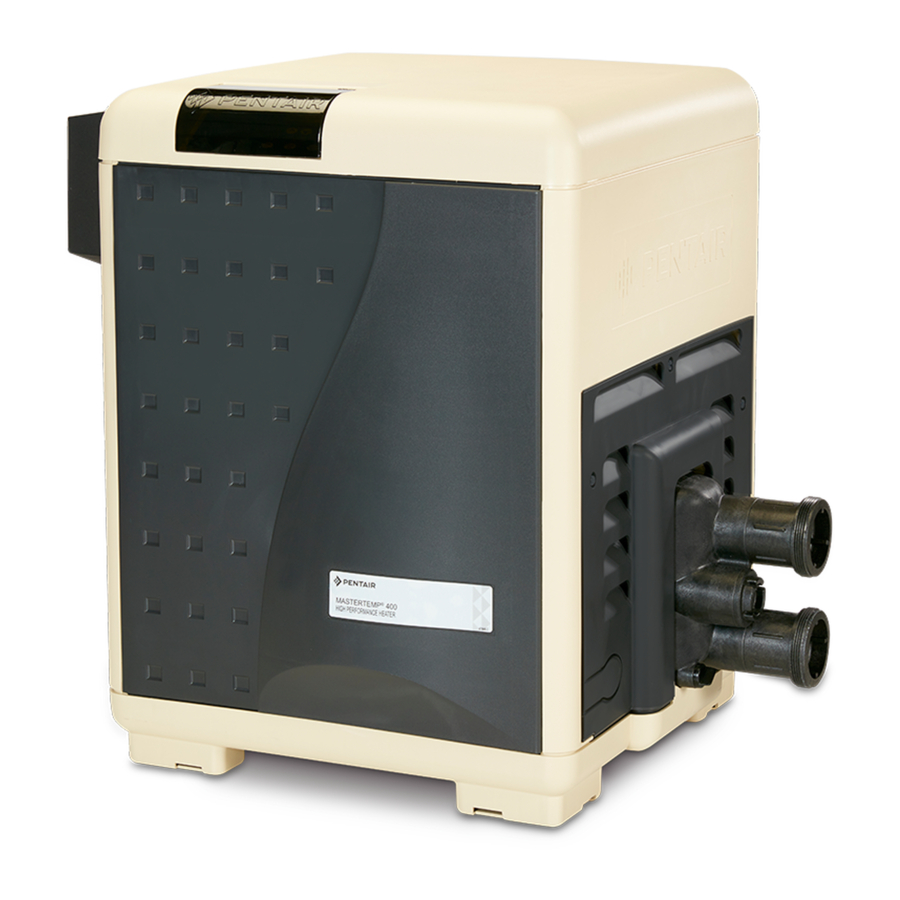
MasterTemp
POOL AND SPA HEATER
120/240 VAC NATURAL
GAS/LP GAS
I N S T A L L A T I O N
a n d
U S E R ' S G U I D E
MODELS
200K BTU/HR
250K BTU/HR
300K BTU/HR
400K BTU/HR
SPECIAL INSTRUCTIONS TO OWNER
Retain this manual for future reference.
This manual supplies information for the installation, operation,
and servicing of the appliance. READ AND REVIEW THIS
MANUAL COMPLETELY before proceeding with an installation.
Its use will reduce service calls and chance of injury and will
lengthen product life.
If the information in these instructions is not followed exactly, a fire
or explosion may result causing property damage, personal injury or death.
Call (800) 831-7133 for additional free copies of these instructions.
FOR YOUR SAFETY
Do not store or use gasoline or other flammable vapors and liquids in the vicinity of this or
any other appliance.
WHAT TO DO IF YOU SMELL GAS
• Do not try to light any appliance.
• Do not touch any electrical switch; do not use any phone in your building.
• Immediately call your gas supplier from a neighbor's phone. Follow the gas supplier's
instructions.
• If you cannot reach your gas supplier, call the fire department.
Installation and service must be performed by a qualified installer, service agency or the gas
supplier.
472592 Rev. A (04/04/06)
Natural
Propane
460730
460731
460732
460733
460734
460735
460736
460737
IMPORTANT SAFETY INSTRUCTIONS
READ AND FOLLOW ALL INSTRUCTIONS
SAVE THESE INSTRUCTIONS
WARNING
TM
®
C E R T I F I E D
®
Publicité
Chapitres
Table des Matières
Dépannage

Manuels Connexes pour Pentair MasterTemp


Sommaire des Matières pour Pentair MasterTemp
- Page 1 MasterTemp C E R T I F I E D ® ® POOL AND SPA HEATER 120/240 VAC NATURAL GAS/LP GAS I N S T A L L A T I O N a n d U S E R ’ S G U I D E...
-
Page 2: Table Des Matières
INSTALLATION, OPERATION Table of Contents Safety ........2 AND SERVICE MANUAL General Specifications, Requirements . -
Page 3: Safety
Read and follow other safety information contained in order for the appliance to satisfactorily meet the application this manual prior to operating this pool heater. needs must be made by a Pentair dealer or other qualified agency using factory specified and approved parts. GENERAL SPECIFICATIONS/... -
Page 4: Description Of The Heater
The heater may not be installed within five feet of the • the high limit switch (HLS), which opens if the heat inside surface of a pool or spa unless it is separated by a exchanger outlet temperature goes above 135° F solid fence, wall or other permanent barrier. -
Page 5: Spa Temperature Caution
C. Use only your hand to turn the gas control on or off. 5. Persons with medical history of heart disease, circula- Never use tools. If you cannot change the ON/OFF tory problems, diabetes or blood pressure problems setting by hand, don’t try to repair it, call a qualified should obtain their physician’s advice before using service technician. -
Page 6: To Switch Off Gas To The Appliance
8. Push the toggle switch away from you to switch the 4. Toggle-Style Valve: Pull toggle toward you to turn gas gas on. off. 9. Replace the Door Access Panels. All panels must be 5. Replace the Access Door Panels. in place when operating the heater. -
Page 7: After Start-Up
The SERVICE SYSTEM light indicates that there is DO NOT operate this unit outdoors at temperatures insufficient water flow to the heater. If the pump is oper- below 40° F (4° C). ating, this usually indicates that the filter and/or skim- During cold weather, if there is no danger of freezing, mers should be cleaned (some filters may require back- operate the filter pump continuously even if the heater is... -
Page 8: Care And Maintenance
CARE AND MAINTENANCE into the manifold. 5. Drain the plastic inlet/outlet manifold through the MAINTENANCE INSTRUCTIONS outlet pipe. If the pipe does not drain naturally to the pool, install a drain cock in the outlet pipe to drain Risk of fire or explosion from flammable WARNING the manifold. -
Page 9: Outdoor Installation
OUTDOOR INSTALLATION INSTRUCTIONS TOP ........3 ft. (1 m) EXHAUST SIDE....6 in. (15 cm) For heaters located outdoors, using the built-in stackless HEADER SIDE....18 in. (.5 m) venting system. DOOR PANELS* ....12 in. (30 cm) Risk of explosion if a unit burning propane WARNING Note (*) For service access it is recommended to leave gas is installed in a pit or other low spot. -
Page 10: Control Panel Indexing
CONTROL PANEL INDEXING protection authorities about specific installation restrictions. The exhaust discharges vertically from outside the vent The heater is design certified by CSA International for cover. The heater control panel assembly located on the installation on combustible flooring; in alcoves; base- top panel can be rotated to any of three positions for ments;... - Page 11 NOTICE: Combustion air contaminated by corrosive from the ceiling for ventilation air and one 12 inches chemical fumes can damage the heater and will void the (30cm) from the floor for combustion air, in accordance warranty (See Table 1 below). with the latest edition of ANSI Z223.1, or the National Fuel Gas code, the CSA B149.1, Natural Gas and Propane HEATER CLEARANCES –...
-
Page 12: Outside Vent Cover Removal
OUTSIDE VENT COVER REMOVAL cloth or paper towel with isopropyl alcohol (rubbing alcohol) and vigorously wipe the socket of the Vent The heater is supplied from the factory with a built-in Body. Immediately wipe the cleaned surfaces dry with stackless outside vent for outdoor installation. Remove a clean cloth or paper towel. - Page 13 5. Use Listed firestop for floor and ceiling penetrations. HORIZONTAL OR VERTICAL VENTING - Use Listed thimble for wall penetrations. Use a Listed POSITIVE PRESSURE (See Figure 13) roof flashing, roof jack, or roof thimble for all roof Vent the heater either horizontally or vertically using one penetrations.
- Page 14 pipe runs up from the heater at least 1/4" per foot Table 4: Vent Termination Height vs. (2cm/M). Install Listed condensate drains at low Roof Pitch – U.S. points where condensate might collect. Plumb con- densate drains to a drain through hard piping or Minimum Height Roof Pitch Above Roof*...
-
Page 15: Final Installation Check
Fire Hazard. Do not run the heater vent WARNING Max 12" into a common vent with any other appliance. Do not run 4' Min. 4' Min. Min 3" Vent Vent the Special Gas Vent into, through, or within any active Termination Termination Vent... -
Page 16: Water Piping
Install a check valve to prevent back-siphoning through the heater when the pump is off. 3-Way Chlorinator Valve NOTICE: Improper operation of chemical feeders can cause severe damage to the heater which is not covered Check valve by the warranty. Install the chemical feeder downstream of the heater (see “Water Chemistry,”... - Page 17 on but the burner should not fire and the blower should not start. If the blower or burner do start, or if the “Service System” light does not go on, there is a pressure switch malfunction. Immediately press the OFF button on the operating control to turn the burner off and call a qualified service technician to check the system.
-
Page 18: Pressure Relief Valve
PRESSURE RELIEF VALVE Explosion hazard. Any heater installed with WARNING Canadian code requires and some U.S. local codes may restrictive devices in the piping system downstream from require installation of a pressure relief valve. Purchase the heater (including check valves, isolation valves, flow separately and install a 3/4"... - Page 19 Instructions For Checking the Gas Pressure Through the Combination Gas Control Valve ‘PRESSURE TAP’ port on the outlet side of the WARNING Risk of fire and explosion. Improper Combination Gas Control Valve. installation, adjustment, alteration, service, or main- 3. Install a 1/8" NPT barbed fitting into the ‘PRESSURE tenance of the Combination Gas Control Valve can TAP’...
-
Page 20: Gas Connections
GAS CONNECTIONS ing system during any pressure testing of that system at test pressures in excess of 1/2 psig (3.5 kPa). The heater requires a gas supply of not less than The heater must be isolated from the gas supply system 4"... -
Page 21: Terminal B Oard
Connect the L1 of the power supply to the black wire, NOTICE: When using a timer and Fireman’s Switch, the the L2 or neutral lead to the red wire, and the ground heater’s power supply should come from the load side of wire to the green wire. - Page 22 6. Reinstall the access door panels. The fuse for the Fireman’s Switch is a 1.25 amp 1-1/4x1/4" fast blow fuse, available locally. MAXIMUM TEMPERATURE SET POINT 1. Unbolt and remove the Door Panels (see Figure 3, Page 5). 2. Access the control panel board on the underside of the top cover.
- Page 23 Initial Troubleshooting Only qualified, trained service technicians with appropriate test equipment should service the heater. Remember that all parts of the system affect heater operation. Before starting this troubleshooting procedure, make sure that the pump is running correctly, that there are no blockages in the system, that the valves are correctly set and that the time clock is correctly set and is running.
- Page 24 Heater Will Not Fire - A Start Depress “POOL” or “SPA” ON Heater should fire on demand Is green “SPA” or button on Membrane Pad. for heat. “POOL” LED “on” Does “POOL” or “SPA” LED come on? Check that correct 12-pin Check for line voltage to Restore power to heater.
- Page 25 Heater Will Not Fire - B Start Increase POOL/SPA tempera- Is red “SERVICE Is red “SERVICE SYSTEM” ture setting on Membrane HEATER” LED “on” LED on? Pad above actual water tem- perature. Heater should fire on demand for heat. If not, Verify that pump is on, filter is and no other red LED’s light, not blocked, and the water...
-
Page 26: Troubleshooting
Heater Will Not Fire - C Start Is “SERVICE HEATER” LED Go to “INITIAL “on”? TROUBLESHOOTING” Turn off power to heater for 5 seconds, Continue to observe heater and turn back on. for several minutes. Cycle Make sure tempera- heater on and off several ture setting is above times. - Page 27 Heater Will Not Fire - D IMPORTANT! READ ME FIRST!! IMPORTANT! READ ME FIRST!! meter will read either 0 VAC or 240 VAC. If your ICM is If your heater is correctly connected to 240 Volts AC, The good, your meter will read some voltage between 0 and Ignition Control Module (ICM) will convert the 240VAC to 240 VAC.
-
Page 28: Diagnostic Led's: Ags, Afs, Hls, Ps, Thermistor
Diagnostic LED’s: AGS, AFS, HLS, PS, THERMISTOR Verify that water flow rate is Service pump and filter to AGS or HLS “on” above minimum required for restore proper flow. After ser- heater. vicing, verify proper operation Replace High Limit of Pressure Switch (PS). Switch (HLS) or Automatic Gas Verify that inlet water temper-... -
Page 29: Diagnostic Led's: Sfs
Diagnostic LED’s: SFS SFS “on” Check Heat Exchanger Coil for leaks, liming, soot, or low flow. Heater starts and runs OK, but temperature of exhaust climbs to 450º–500º in 3–5 Check Thermal minutes. Regulator: Open at 120º? Replace Heater (HD ) Membrane Pad. - Page 30 Burner Troubleshooting SYMPTOM CAUSE REMEDY Loud, high-pitched whine Flame is too rich. Verify pressure tap between gas valve and blower inlet. Turn to Page 19 and verify that the regulator setting is 0.2" (0.5cm) wc below the blower inlet pressure. Replace gas orifice with smaller size.
-
Page 31: Repair Parts
(Key Nos. 5 through 9), See Pages 32 and 33 For complete Water System parts breakdown (Key Nos. 10 through 13), see Page 34 Repair Parts are available from your Pentair dealer. If your dealer cannot supply you, call Customer Support at 1-800-831-7133. - Page 32 For Heater mounting bolts and clamps, purchase separately Bolt Down Bracket Kit, Part No. 460738.
- Page 33 REPAIR PARTS – BURNER SYSTEM Model Part 200NA 250NA 300NA 400NA Description Qty. 200LP 250LP 300LP 400LP Combination Gas Control Valve Kit 42001-0051S 42001-0051S 42001-0051S 42001-0051S 3/4" Union 38404-4097S 38404-4097S 38404-4097S 38404-4097S Gas Orifice • Gas Orifice Kit – NG (Incl. Key Nos. 3 and 4)† 77707-0431 460739 460753...
- Page 34 REPAIR PARTS – WATER SYSTEM Model Part 200NA 250NA 300NA 400NA Description Qty. 200LP 250LP 300LP 400LP Tube Sheet Coil Assembly Kit (NA, LP Series) (Includes Key No.3) 77707-0232 460747 77707-0233 77707-0234 Manifold Kit (Includes Key Nos. 3-14, 21, and Key Nos.
- Page 35 REPAIR PARTS – ELECTRICAL SYSTEM Model Part 200NA 250NA 300NA 400NA Description Qty. 200LP 250LP 300LP 400LP Heater Display Cover 42002-0035 42002-0035 42002-0035 42002-0035 Igniter Bracket 42001-0030S 42001-0030S 42001-0030S 42001-0030S Igniter/Igniter Gasket Kit Incl. Key Nos. 4 and 5) 77707-0054 77707-0054 77707-0054 77707-0054...
-
Page 36: Connection Diagram
Pool Heater Wiring Connection Diagram CONNECTION DIAGRAM AGS Switch Air Flow Switch Stack Flue Sensor Extra Switch 1 Gas Valve Y/BL Hi-Limit Switch Pressure Switch NA/LP Models Only Y/BL OPERATING CONTROL MEMB RANE PAD CONNECTIO N NA/LP Models: J6 incl. pins 1-6; Connect 9-Wire External Control Interface Circuit Disabled, Cable as shown... -
Page 37: Ladder Diagram
Pool Heater Electrical Schematic Ladder Diagram LADDER DIAGRAM 120/240 IGNITER BLOWER 120/240 CLASS II TRANSFORMER 24 VAC OPERATING CONTROL 24 VAC 24 VAC FLOW LOGIC SWITCH WATER LIMIT PRESSURE SWITCH SWITCH COM NO SWITCH GAS VALVE STACK FLUE THERMISTOR SENSOR SENSOR NOTES: 24 VAC... -
Page 38: Customer Support
Trademarks and disclaimers: MasterTemp and the Pentair Pool Products and Pentair Water Pool and Spa logos are trade- marks of Pentair Water Pool and Spa, Inc. Other trademarks and trade names may be used in this document to refer to either the entities claiming the marks and names or their products. -
Page 39: Instructions Spéciales Pour Le Propriétaire
MasterTemp C E R T I F I E D ® ® CHAUFFE-PISCINE/SPA C.A. 120/240 VOLTS AU GAZ NATUREL/GPL N O T I C E D ’ U T I L I S A T I O N INSTALLATION, FONCTIONNEMENT ET PIÈCES MODÈLES... -
Page 40: Codes D'installation Des Appareils Et Des Équipements
Code canadien de l’électricité ou du National Electrical Code, ANSI/NFPA70, selon le cas. FIGURE 1: MasterTemp chauffe-piscine/spa Pour les instructions concernant la méthode de contrôle de la pression du gaz avec la soupape à gaz mixte, se reporter à l'encadré de la page 19. -
Page 41: Instructions Concernant La Sécurité (Suite)
INSTRUCTIONS CONCERNANT piscine/spa, suivre les instructions d'évacuation des gaz brûlés exactement comme elles sont indiquées. Ne pas LA SÉCURITÉ (suite) utiliser de coupe-tirage avec ce chauffe-piscine/spa étant donné que la soufflante du brûleur pressurise les AVERTISSEMENT gaz brûlés et qu'un coupe-tirage reverra les produits de Cet appareil est équipé... -
Page 42: Description Du Chauffe-Piscine/Spa
Ce chauffe-piscine/spa doit être installé à au moins cinq pieds l'intermédiaire d'une série de dispositifs de sécurité. Les de la paroi intérieure d'une piscine ou d'un spa, si une clôture, dispositifs de sécurité se composent : un mur ou toute autre barrière massive permanente ne les •... -
Page 43: Précautions À Prendre Concernant La Température Des Spas
N’ouvrir et ne fermer la commande du gaz qu’à la main. Ne INSTRUCTIONS DE FONCTIONNEMENT jamais utiliser d’outils. Si le réglage MARCHE-ARRÊT ne peut ARRÊT! Lire les instructions relatives aux consignes de pas être modifié à la main, ne pas essayer de réparer. sécurité... -
Page 44: Pour Couper L'arrivée De Gaz Au Chauffe-Piscine/Spa
Attendre cinq (5) minutes pour que tout le gaz soit évacué. POUR COUPER L'ARRIVÉE DE GAZ AU CHAUFFE- Si on sent une odeur de gaz, ARRÊTER! Suivre les instruc- PISCINE/SPA tions «B» figurant sous «Avant la mise en marche» (page Appuyer sur la touche «... -
Page 45: Après La Mise En Marche
Le témoin HEATING (CHAUFFAGE) s'allume et reste allumé AVIS : Lorsque l'on remet le chauffe-piscine/spa en marche pendant que le brûleur fonctionne. Il clignote si l'eau du pour la saison de baignade, et que la température de l'eau est chauffe-piscine/spa doit être chauffée mais que le brûleur ne inférieure à... -
Page 46: Entretien/Instructions D'entretien/Hiverisation
ENTRETIEN AVERTISSEMENT Risque d'explosion. Purger le circuit avec INSTRUCTIONS D'ENTRETIEN de l'air comprimé risque de faire exploser les composants et d'entraîner de graves blessures, voire la mort, à toutes les AVERTISSEMENT Les vapeurs inflammables risquent de causer personnes se tenant à proximité. N'utiliser qu'une soufflette un incendie ou une explosion. -
Page 47: Instructions Concernant Les Installations Extérieures
INSTRUCTIONS CONCERNANT Orienter le chauffe-piscine/spa de façon à pouvoir facilement accéder aux branchements d'eau et de gaz, de même qu'aux LES INSTALLATIONS EXTÉRIEURES connexions électriques. Chauffe-piscine/spa installés à l'extérieur et utilisant le système Installer le chauffe-piscine/spa à au moins 18 pouces (45 cm) de la limite de toute propriété. -
Page 48: L'extérieur Dans Un Abri
INDEXAGE DU BLOC DE COMMANDE norme CAN/CSA B149.2 (dernière édition) relative à l'entre- posage et à la manipulation du propane ou à la dernière édition Les gaz brûlés sont refoulés verticalement par l'extérieur du de la norme 58 de l’ANSI/NFPA. Consulter les codes de la couvercle d'évacuation.Le bloc de commande du chauffe- municipalité... -
Page 49: Installation Intérieure (États-Unis)
CHAUFFE-PISCINES/SPAS INSTALLÉS À CONDUIT D’ÉVACUATION DES L'EXTÉRIEUR DANS UN ABRI GAZ DANS UN ABRI INSTALLATION EXTÉRIEURE Les dégagements suivants doivent être respectés avec toutes les surfaces combustibles : (Canada) OU Au-Dessus.........1 mètre (3 pieds) Tableau 2 : Exigences en matière d'air de Côté... -
Page 50: Dépose Du Couvercle Extérieur Du Conduit Des Gaz Brûlés
DÉPOSE DU COUVERCLE EXTÉRIEUR trouve sous le couvercle extérieur du conduit d'évacuation DU CONDUIT DES GAZ BRÛLÉS des gaz brûlés). Fixer la buse métallique sur le corps du conduit d'évacuation des gaz brûlés avec deux vis à métaux Pour les installations extérieures, le chauffe-piscine/spa est livré n°... -
Page 51: Conduit D'évacuation Des Gaz Brûlés Hozontal Ou Vertical - Pression Positive
gaz brûlés installés à l'horizontale doit être d'au moins 1/4 conduit d'évacuation des gaz brûlés soit bien à la verticale. de pouce par pied (2 cm par mètre) à partir du chauffe- Ne pas brancher le conduit d'évacuation des gaz piscine/spa. - Page 52 chauffe-piscine/spa ou le corps du conduit d'évacuation des gaz Tableau 4 : Hauteurs de la terminaison du con- brûlés. L'inclinaison des conduits d'évacuation des gaz brûlés duit d’évacuation des gaz brûlés par installés à l'horizontale doit être d'au moins 1/4 de pouce (2 cm per meter) par pied à...
-
Page 53: Vérification Finale De L'installation
pas planter d'arbrisseaux à proximité du mitre du conduit d'é- vacuation des gaz brûlés. Pour empêcher la formation de tach- Terminaison es ou la détérioration, il faudra peut-être rendre étanches ou du conduit Max. 12 po 4 pi minimum 4 pi minimum protéger les surfaces exposées. -
Page 54: Composition Chimique De L'eau
S'assurer que la tuyauterie de refoulement du chauffe- avoir installé la vanne, la régler de façon à obtenir un débit cor- piscine/spa ne comporte aucune vanne ou obstruction du débit respondant à la gamme acceptable. Déposer ensuite la poignée qui risquerait d'empêcher l'eau de circuler dans le chauffe- de la vanne et verrouiller la vanne pour empêcher que son piscine/spa (sauf comme il est indiqué... - Page 55 Attendre une minute. Le témoin «Service System» doit AVERTISSEMENT Risque de vapeur vive. Si le brûleur et la s'allumer, mais le brûleur ne doit pas s'allumer et la pompe s'arrêtent de fonctionner en même temps, atten- soufflante ne doit pas démarrer. Si la soufflante démarre ou dre au moins 15 minutes avant de redémarrer la pompe si le brûleur s'allume, ou si le témoin «Service System»...
-
Page 56: Soupape De Sûreté
SOUPAPE DE SÛRETÉ Le code canadien exige et, aux États-Unis certains codes des municipalités peuvent l’exiger, l’installation d’une soupape de sûreté. Acheter et installer séparément une soupape de sûreté de 3/4 po ayant une capacité égale au débit en Btu/h du Relief Valve Installed chauffe-piscine/spa et conforme au code ANSI/ASME «... -
Page 57: Instructions Pour Vérifier La Pression Du Gaz Par La Soupape À Gaz Mixte
Instructions pour vérifier la pression du gaz par la soupape à gaz mixte 2. Utiliser une clé à six pans de 3/16 de pouce pour déposer AVERTISSEMENT Risque d'incendie et d'explosion. Toute l'obturateur de l'orifice «PRESSURE TAP», côté sortie de mauvaise installation, tout mauvais réglage, toute trans- la soupape à... -
Page 58: Branchements Du Gaz
BRANCHEMENTS DU GAZ AVERTISSEMENT Risque d'incendie ou d'explosion. Ne pas L'arrivée du gaz au chauffe-piscine/spa doit être d'au moins 4 utiliser une flamme nue pour procéder au contrôle des pouces (10,2cm) à la colonne d'eau et ne pas dépasser 14 fuites. -
Page 59: Branchement De L'interrupteur De Coupure Pompier
Ne pas brancher d'interrupteurs unipolaires, y compris des NOTA : Lorsque l'on utilise un programmateur et un interrup- dispositifs de protection, sur le câble de mise à la terre. Le teur de coupure pompier, le courant alimentant le chauffe- chauffe-piscine/spa n’est pas sensible à la polarité. piscine/spa doit arriver du côté... -
Page 60: Valeur De Réglage De La Température Maximum
Reposer les moitiés les panneaux de la porte d'accès. Le fusible de l'interrupteur de coupure pompier est un fusible de 1,25 ampère de 1 1/4 x 1/4 de pouce à fusion rapide que l'on devra acheter localement. VALEUR DE RÉGLAGE DE LA TEMPÉRATURE MAXIMUM Dévisser les panneaux de la Porte d'Accès, puis les déposer (se reporter à... -
Page 61: Recherches Initiales Des Pannes
Recherches initiales des pannes Seuls des techniciens qualifiés et formés possédant les instruments de contrôle appropriés doivent intervenir sur le chauffe- piscine/spa. Il faut se rappeler que toutes les pièces du système affectent le fonctionnement du chauffe-piscine/spa. Avant de procéder à cette recherche des pannes, s'assurer que la pompe fonctionne bien, que le système n'est pas obstrué, que les robi- nets et vannes sont bien réglés et que le programmateur est bien réglé... - Page 62 Le chauffe-piscine/spa ne s'allume pas - A Début Est-ce que la DEL verte « Le chauffe-piscine/spa doit s’allumer Appuyer sur la touche « POOL ON » SPA » ou « POOL » est lorsqu’il y a demande de chaleur. ou « SPA ON » du clavier à mem- allumée? brane.
- Page 63 Le chauffe-piscine/spa ne s'allume pas - B Début Augmenter le réglage de la tempéra- Est-ce que la DEL rouge Est-ce que la DEL «SERVICE ture du CHAUFFE-PISCINE/SPA «SERVICE HEATER» est SYSTEM» est allumée? avec le clavier à membrane par rap- allumée? port à...
- Page 64 Le chauffe-piscine/spa ne s'allume pas - C Début Est-ce que la DEL «SERVICE Passer à «RECHERCHES INITIALES HEATER» est allumée? DES PANNES» Couper le courant alimen- tant le chauffe-piscine/spa Continuer d'observer le chauffe- pendant environ 5 secon- piscine/spa pendant plusieurs min- des, puis le rétablir.
-
Page 65: Le Chauffe-Piscine/Spa Ne S'allume Pas - D
Le chauffe-piscine/spa ne s'allume pas - D IMPORTANT! - À LIRE EN PREMIER!! IMPORTANT! - À LIRE EN PREMIER!! meilleure lecture qu’un voltmètre numérique.) Si le module ICM est défectueux, la lecture sera de 0 volt ou de 240 volts de c.a. Si Si le chauffe-piscine/spa est bien relié... - Page 66 DEL de diagnostic : AGS, AFS, HLS, PS et THERMISTANCE Confirmer que le débit de l’eau est Entretenir la pompe et le filtre pour AGS ou HLS allumé supérieur au minimum requis pour le rétablir le bon débit. Après l’entre- chauffe-piscine/spa.
- Page 67 DEL de diagnostic : SFS DEL de diagnostic : SFS Inspecter le serpentin de l’échangeur de chaleur à la recherche de fuites, de tartre, de suie ou d’un débit faible. Remplacer le clavier Le chauffe-piscine/spa démarre à membrane du et fonctionne bien, mais la tem- (HD ) chauffe-piscine/spa.
-
Page 68: Recherche Des Pannes Du Brűleur
Recherche des pannes du brűleur SYMPTÔMES CAUSES REMÈDES Fort bruit aigu de gémissement La flamme est trop riche. Vérifier la prise de pression, entre la soupape à gaz et l'arrivée de la soufflante. Passer à la page 19 et confirmer que le réglage du régulateur des gaz est de 0,2 pouce (0.5cm) à... - Page 69 (Réf. 10 à 13), se reporter à la page 34 On peut se procurer des pièces de rechange auprès du concessionnaire Pentair. Si votre concessionnaire ne peut pas fournir ce dont vous avez besoin, appelez le Service à la clientèle Pentair au (800)-831-7133.
- Page 70 Pour les vis et les colliers de fixation du chauffe- piscine/spa, acheter séparément le nécessaire de upport de fixation, n° de pièce 466738...
-
Page 71: Pièces De Rechange
PIÈCES DE RECHANGE DU SYSTÈME DU BRÛLEUR Modèle Désignation 200NA 250NA 300NA 400NA Réf. des pièces Qté 200LP 250LP 300LP 400LP Trousse de soupape de commande de gaz mixte 4201-0051S 4201-0051S 42001-0051S 42001-0051S Raccord-union de 3/4 de pouce 38404-4097S 38404-4097S 38404-4097S 38404-4097S Orifice de gaz... -
Page 72: Pièces De Rechange Du Système D'eau
PIÈCES DE RECHANGE DU SYSTÈME D'EAU Modèles Désignation 200NA 200NA 300NA 400NA Réf. des pièces Qté 200LP 200LP 300LP 400LP Trousse de serpentin tubulaire (Séries NA, LP) (Comprend le Réf. 3) 77707-0232 460747 77707-0233 77707-0234 Trousse de tubulure (Comprend les Réf. 3 à 14, 21 et 7 à... -
Page 73: Pièces De Rechange Du Système Électrique
PIÈCES DE RECHANGE DU SYSTÈME ÉLECTRIQUE Modèles Désignation 200NA 250NA 300NA 400NA Réf. des pièces Qté 200LP 250LP 300LP 400LP Couvercle de présentoir de chauffe-piscine/spa 42002-0035 42002-0035 42002-0035 42002-0035 Support d’allumeur 42001-0030S 42001-0030S 42001-0030S 42001-0030S Trousse de joint d’allumeur/allumeur (Comprend les Réf. 4 et 5) 77707-0054 77707-0054 77707-0054... -
Page 74: Schéma Des Connexions Électriques Du Chauffe-Piscine/Spa
Schéma des connexions électriques du chauffe-piscine/spa SCHÉMA DES CONNEXIONS Débitmètre d’air Interrupteur AGS Interrupteur Sonde du conduit supplémentaire d’évacuation des gaz brûlés Interrupteur Robinet de gaz Y/BL à maximum Manostat Modèles NA/LP seulement Y/BL BLOC DE COMMANDE D’UTILISATION CONNEXION DU CLAVIER À... -
Page 75: Diagramme En Échelle Du Schéma Électrique Du Chauffe-Piscine/Spa
Diagramme en échelle du schéma électrique du chauffe-piscine/spa DIAGRAMME EN ESCALIER SOUS NEUTRE C. a. 120 V TENSION DISPOSITIF D'ALLUMAGE SOUFFLANTE TERRE C. a. 120 V TRANSFO RMATEUR DE CATÉGORIE II C. a. 24 V COMM AN DE DE FONCIONNE M ENT C. -
Page 76: Préserver Ces Instructions
Marques déposées et désaveux: MasterTemp et les produits de Pentair Pool et les symboles de Pentair Water Pool and Spa, Inc. sont des marques déposées de Pentair Water Pool and Spa, Inc. Les autres marques déposées et les noms de commerce peuvent être utilisés dans ce document pour se référer soit aux parties réclamant les marques et les noms ou...